EP1083066A2 - Ringförmiger Notlaufstützkörper für Fahrzeugreifen, und Rad mit demselben - Google Patents
Ringförmiger Notlaufstützkörper für Fahrzeugreifen, und Rad mit demselben Download PDFInfo
- Publication number
- EP1083066A2 EP1083066A2 EP00119215A EP00119215A EP1083066A2 EP 1083066 A2 EP1083066 A2 EP 1083066A2 EP 00119215 A EP00119215 A EP 00119215A EP 00119215 A EP00119215 A EP 00119215A EP 1083066 A2 EP1083066 A2 EP 1083066A2
- Authority
- EP
- European Patent Office
- Prior art keywords
- profile
- rim
- support body
- features
- bead
- Prior art date
- Legal status (The legal status is an assumption and is not a legal conclusion. Google has not performed a legal analysis and makes no representation as to the accuracy of the status listed.)
- Granted
Links
- 229920001971 elastomer Polymers 0.000 claims abstract description 24
- 239000011324 bead Substances 0.000 claims description 116
- 239000000945 filler Substances 0.000 claims description 38
- 230000015556 catabolic process Effects 0.000 claims description 16
- 239000013536 elastomeric material Substances 0.000 claims description 2
- 230000000737 periodic effect Effects 0.000 claims description 2
- 239000000806 elastomer Substances 0.000 abstract 1
- 239000000463 material Substances 0.000 description 17
- 230000015572 biosynthetic process Effects 0.000 description 10
- 239000004033 plastic Substances 0.000 description 7
- 238000005299 abrasion Methods 0.000 description 6
- 230000002787 reinforcement Effects 0.000 description 6
- 230000000694 effects Effects 0.000 description 5
- 230000002093 peripheral effect Effects 0.000 description 5
- DOSMHBDKKKMIEF-UHFFFAOYSA-N 2-[3-(diethylamino)-6-diethylazaniumylidenexanthen-9-yl]-5-[3-[3-[4-(1-methylindol-3-yl)-2,5-dioxopyrrol-3-yl]indol-1-yl]propylsulfamoyl]benzenesulfonate Chemical compound C1=CC(=[N+](CC)CC)C=C2OC3=CC(N(CC)CC)=CC=C3C(C=3C(=CC(=CC=3)S(=O)(=O)NCCCN3C4=CC=CC=C4C(C=4C(NC(=O)C=4C=4C5=CC=CC=C5N(C)C=4)=O)=C3)S([O-])(=O)=O)=C21 DOSMHBDKKKMIEF-UHFFFAOYSA-N 0.000 description 4
- 229910000831 Steel Inorganic materials 0.000 description 4
- 238000005452 bending Methods 0.000 description 4
- 238000009434 installation Methods 0.000 description 4
- 238000004519 manufacturing process Methods 0.000 description 4
- 239000010959 steel Substances 0.000 description 4
- 230000007704 transition Effects 0.000 description 4
- 230000006835 compression Effects 0.000 description 3
- 238000007906 compression Methods 0.000 description 3
- 230000006378 damage Effects 0.000 description 3
- 230000036316 preload Effects 0.000 description 3
- 230000008719 thickening Effects 0.000 description 3
- VYPSYNLAJGMNEJ-UHFFFAOYSA-N Silicium dioxide Chemical compound O=[Si]=O VYPSYNLAJGMNEJ-UHFFFAOYSA-N 0.000 description 2
- 238000004873 anchoring Methods 0.000 description 2
- 238000010276 construction Methods 0.000 description 2
- 239000013013 elastic material Substances 0.000 description 2
- 239000002184 metal Substances 0.000 description 2
- 239000000203 mixture Substances 0.000 description 2
- 238000007142 ring opening reaction Methods 0.000 description 2
- 239000004753 textile Substances 0.000 description 2
- 239000004677 Nylon Substances 0.000 description 1
- 230000009471 action Effects 0.000 description 1
- 230000001154 acute effect Effects 0.000 description 1
- 239000004760 aramid Substances 0.000 description 1
- 229920003235 aromatic polyamide Polymers 0.000 description 1
- 230000008901 benefit Effects 0.000 description 1
- 230000008859 change Effects 0.000 description 1
- 150000001875 compounds Chemical class 0.000 description 1
- 238000013016 damping Methods 0.000 description 1
- 230000003111 delayed effect Effects 0.000 description 1
- 238000001125 extrusion Methods 0.000 description 1
- 239000004744 fabric Substances 0.000 description 1
- 230000020169 heat generation Effects 0.000 description 1
- 238000002347 injection Methods 0.000 description 1
- 239000007924 injection Substances 0.000 description 1
- 238000001746 injection moulding Methods 0.000 description 1
- 238000000034 method Methods 0.000 description 1
- 229920001778 nylon Polymers 0.000 description 1
- 230000002028 premature Effects 0.000 description 1
- 230000003014 reinforcing effect Effects 0.000 description 1
- 230000000717 retained effect Effects 0.000 description 1
- 230000035939 shock Effects 0.000 description 1
- 239000000377 silicon dioxide Substances 0.000 description 1
- 239000007779 soft material Substances 0.000 description 1
- 239000007787 solid Substances 0.000 description 1
- 238000004804 winding Methods 0.000 description 1
Images


Classifications
-
- B—PERFORMING OPERATIONS; TRANSPORTING
- B60—VEHICLES IN GENERAL
- B60C—VEHICLE TYRES; TYRE INFLATION; TYRE CHANGING; CONNECTING VALVES TO INFLATABLE ELASTIC BODIES IN GENERAL; DEVICES OR ARRANGEMENTS RELATED TO TYRES
- B60C15/00—Tyre beads, e.g. ply turn-up or overlap
- B60C15/02—Seating or securing beads on rims
- B60C15/0203—Seating or securing beads on rims using axially extending bead seating, i.e. the bead and the lower sidewall portion extend in the axial direction
-
- B—PERFORMING OPERATIONS; TRANSPORTING
- B60—VEHICLES IN GENERAL
- B60C—VEHICLE TYRES; TYRE INFLATION; TYRE CHANGING; CONNECTING VALVES TO INFLATABLE ELASTIC BODIES IN GENERAL; DEVICES OR ARRANGEMENTS RELATED TO TYRES
- B60C15/00—Tyre beads, e.g. ply turn-up or overlap
- B60C15/02—Seating or securing beads on rims
- B60C15/0206—Seating or securing beads on rims using inside rim bead seating, i.e. the bead being seated at a radially inner side of the rim
-
- B—PERFORMING OPERATIONS; TRANSPORTING
- B60—VEHICLES IN GENERAL
- B60C—VEHICLE TYRES; TYRE INFLATION; TYRE CHANGING; CONNECTING VALVES TO INFLATABLE ELASTIC BODIES IN GENERAL; DEVICES OR ARRANGEMENTS RELATED TO TYRES
- B60C15/00—Tyre beads, e.g. ply turn-up or overlap
- B60C15/02—Seating or securing beads on rims
- B60C15/0209—Supplementary means for securing the bead
- B60C15/0213—Supplementary means for securing the bead the bead being clamped by rings, cables, rim flanges or other parts of the rim
-
- B—PERFORMING OPERATIONS; TRANSPORTING
- B60—VEHICLES IN GENERAL
- B60C—VEHICLE TYRES; TYRE INFLATION; TYRE CHANGING; CONNECTING VALVES TO INFLATABLE ELASTIC BODIES IN GENERAL; DEVICES OR ARRANGEMENTS RELATED TO TYRES
- B60C17/00—Tyres characterised by means enabling restricted operation in damaged or deflated condition; Accessories therefor
- B60C17/04—Tyres characterised by means enabling restricted operation in damaged or deflated condition; Accessories therefor utilising additional non-inflatable supports which become load-supporting in emergency
- B60C17/047—Tyres characterised by means enabling restricted operation in damaged or deflated condition; Accessories therefor utilising additional non-inflatable supports which become load-supporting in emergency comprising circumferential ribs
-
- B—PERFORMING OPERATIONS; TRANSPORTING
- B60—VEHICLES IN GENERAL
- B60C—VEHICLE TYRES; TYRE INFLATION; TYRE CHANGING; CONNECTING VALVES TO INFLATABLE ELASTIC BODIES IN GENERAL; DEVICES OR ARRANGEMENTS RELATED TO TYRES
- B60C17/00—Tyres characterised by means enabling restricted operation in damaged or deflated condition; Accessories therefor
- B60C17/04—Tyres characterised by means enabling restricted operation in damaged or deflated condition; Accessories therefor utilising additional non-inflatable supports which become load-supporting in emergency
- B60C17/06—Tyres characterised by means enabling restricted operation in damaged or deflated condition; Accessories therefor utilising additional non-inflatable supports which become load-supporting in emergency resilient
- B60C2017/068—Tyres characterised by means enabling restricted operation in damaged or deflated condition; Accessories therefor utilising additional non-inflatable supports which become load-supporting in emergency resilient comprising springs, e.g. helical springs
Definitions
- the invention relates to an annular support body for supporting the tread Pneumatic vehicle tire in a vehicle wheel in emergency running or in the flat running of the vehicle wheel by supporting the tread on the radial outer surface of the annular Support body and a vehicle wheel with such a support ring.
- annular support body for supporting the tread of a pneumatic vehicle tire in a vehicle wheel in emergency running or in the flat running of a vehicle wheel by supporting the tread on the radial outer surface of the annular support body, wherein the annular support body is made of elastomeric material and with a profile which comprises parallel profile grooves, a profile rib being enclosed between each two adjacent profile grooves, the cross-sectional contour of which in a sectional area perpendicular to the rib course is to the side of the profile grooves enclosing them, each through a side face and is delimited by a radial outer side connecting the two side surfaces in their radial end region, is known for example from EP 0 796 747 A1.
- the cross-sectional contour in a cut surface perpendicular to the course of the ribs Profile ribs are essentially rectangular.
- the side surfaces extend straight in radial direction outwards.
- the radial outside of this each between two Profile grooves arranged profile ribs each form cylindrical surfaces, so that in Emergency or breakdown run at the moment of contact of the support body with the tread the tread immediately over the entire width of the radial outside of the individual Profile rib rests and is supported. This will - as for good durability suitability desired - a large support surface in emergency run or breakdown run achieved.
- the contour of the Profile rib corresponds substantially to the contour of the known support bodies Profile ribs in the tread of a pneumatic vehicle tire, in which the profile ribs are used to achieve this good ground grip have a substantially cylindrical radial outer surface.
- Requirements - such as traction, wet grip, etc. - as from mixtures for the Treads are required for the emergency running surface.
- Requirements - such as traction, wet grip, etc. - as from mixtures for the Treads are required for the emergency running surface.
- At Emergency support bodies are due to the different requirements for the Run-flat support surface is generally softer than the tread of the pneumatic vehicle tire Preferred rubber compounds, which should enable special comfort in emergency running, are abrasion-resistant and should only allow low heat build-up.
- the profile ribs are subject to strong alternating stresses, in particular bending stresses around its longitudinal axis.
- the strong, changing Bends can occur after a relatively short loading time soft materials in the profile structure to tear in the transition areas between Sidewall and radial outside and in the transition area of the profile ribs and run between the side wall and the profile groove base.
- the Alternating bending to an undesired degree generates heat in the profile. This too can the profile will be destroyed early. The durability is therefore more effective despite great Support area reduced.
- the operability of a vehicle wheel with such a Support body in the emergency run or breakdown run can be undesirably limited in time become.
- the invention is based, in a simple manner, the emergency running or the task Breakdown ability of an annular support body to support the tread of a Pneumatic vehicle tire in a vehicle wheel in emergency running or in the flat running of the vehicle wheel by supporting the tread on the radial outer surface of the annular Support body according to the features of the preamble of claim 1 when used in emergency or Improve breakdown running in a vehicle wheel.
- the object is achieved by the formation of an annular support body to support the tread of a pneumatic vehicle tire in a vehicle wheel in emergency running or in the flat running of the vehicle wheel by supporting the tread on the radial Outer surface of the annular support body according to the features of claim 1 and by a vehicle wheel according to the features of claim 15 solved.
- the formation of the arranged between the profile grooves profile rib with an in unloaded state in the area of the radial outside convexly curved Cross-sectional contour causes that at the moment of contact with the tread of the Vehicle tire in emergency running or flat running initially only substantially linear Contact occurs between the profile rib and the tread and then under the load the profile rib is radially compressed at least in its outer radial region, wherein the radial outside is widened, so that in the state of the actual support effect a correspondingly larger effective support surface between the profile ribs and the tread is produced.
- the delayed appearance of the effective size of the support surface due to Deformation of the profile rib, which is convex in the unloaded state additionally increases the Comfort of the vehicle wheel in emergency running or flat running.
- the profile rib due to the different radial extents along the convex Curvature curve additionally stiffened in the loaded state, so that the Alternating loads result in less pronounced bending of the profile rib.
- the Heat generation can be reduced.
- the risk of destruction by tearing out the Profile rib can be largely prevented.
- the durability of the support body in emergency running or breakdown run is improved.
- the bending stiffness of the profile ribs is additionally increased and the risk of destruction can be further reduced.
- the training according to the features of claim 4 enables a flowing Transition of the contour of a profile rib, which further increases the rigidity can be.
- the training according to the features of claim 9 is particularly advantageous because hereby the risk of mutual negative influence on the profiling of Tread and that of the support element in the emergency run or breakdown run on the respective Function can be reliably minimized.
- Claims 12 and 13 represent preferred embodiments
- the formation of the profile ribs with a periodically curved in the circumferential direction - especially wave-shaped - allows additional stiffening of the Profile ribs, which have a particularly good setting of the handling properties of the Allow vehicle wheel in emergency run or breakdown run.
- the amplitudes are preferred and / or frequency of the periodic curvature constant over the circumference.
- the training according to the features of claim 14 allows an additional Stiffening of the profile ribs through mutual connection.
- the design of a vehicle wheel according to the features of claim 16 is preferred to achieve particularly good emergency running properties, since forces from the Treads can be introduced into the rim in the same axial position as in Normal operation.
- the design of the vehicle wheel according to claim 17 allows in a simple manner that Rim surface completely available for designing an emergency run support surface stands and the tire is still reliable and simple, namely in the end face of the rim can be attached. After inserting the bead into the annular chamber, the filler ring becomes the annular chamber is inserted and the bead thereby positively to the annular chamber fixed.
- the bead core which can be changed in its circumferential length - in particular elastically - is possible the assembly of the bead by moving over the radially outer surface of the rim - especially over the emergency running surface - with a larger bead core diameter than in the attached operating state of the bead and for movement over the rim flange a smaller bead core diameter than when fastened, so that the Formation of the radially outer lateral surface of the rim - in particular the Emergency running support surfaces - no longer depending on the diameter of the bead core in the Operating condition and the inner rim flange diameter, but primarily after other criteria - e.g.
- the filler ring After inserting the bead into the annular chamber, the filler ring becomes radial inserted axially into the annular chamber within the bead, so that between the radially inner Annular chamber wall and filler ring, between filler ring and bead and between bead and radial outer annular chamber wall radial positive locking and at least between the bead and the axially outer ring chamber wall forming rim flange axial positive locking is produced.
- the one in its circumferential length changeable bead can thus be both assembled and in a simple and reliable manner can also be dismantled whereby both the emergency running support surfaces are optimized for emergency running also the rim flange with regard to the axial support for the bead and the bead core in optimized its operating state with regard to its properties in the operating state can be.
- the introduction of force into the rim is particularly safe when the bead is over its entire axial extension lies completely radially inward on the filling ring. If the bead and the filler ring completely fill the ring chamber becomes a special one Reliable positive locking between bead and rim achieved.
- the training according to the features of claim 20 is preferred for achieving Particularly good emergency running properties, since forces from the tread thereby can be introduced into the rim in the same axial position as in normal operation. In addition, this is essential when driving over a curb, for example stressed tread edge area in emergency run or breakdown run by the Support body supported.
- the arrangement on both sides enables a special security when in both tread edge areas.
- An alternative advantageous training to achieve particularly good emergency running properties is the training according to the features of claim 21, because forces in emergency running can be introduced into the rim from the tread in the same axial position as in normal operation.
- this is, for example, when driving over a curb significantly used tread edge area also in emergency or breakdown the support body is supportable and the tread is supported over a very wide area, so that a great support effect can also be achieved in the crown area of the tread.
- the bead core is a rubber core integrated in the bead.
- the rubber core is easy to manufacture and can be particularly simple and reliable in Bead to be anchored.
- the bead can thereby in a simple, reliable manner its circumferential length can be made elastically stretchable.
- Seat is the rubber core with a Shore -A- hardness in the range from 80 to 100 - preferably formed in the range between 85 to 90.
- a vehicle wheel which is the largest outside diameter of the emergency running surfaces by a factor between 1.05 and 1.3 larger than the inner ring diameter of the bead core in the assembled state of the Vehicle wheel, enables optimal emergency running properties due to particularly large Outside diameter of the emergency running support surfaces while maintaining the good to achieve Deflection of the tire and thus good comfort properties optimal smaller Inner ring diameter of the bead core.
- the formation of a vehicle wheel in which the bead core has an extensibility and / or Compressibility of 5 to 30% enables simple and reliable installation despite optimal emergency running properties by training particularly large Outside diameter of the emergency support surfaces despite maintaining the achievement of the achievement good tire deflection and thus good comfort properties thanks to the optimally small size Inner ring diameter of the bead core.
- the bead is in each case on the for assembly or Disassembly over the emergency running surfaces required optimal diameter to the Assembly or disassembly required using the inward-facing rim flange optimal diameter and on the necessary for a secure fit in the ring chamber optimal diameter set.
- Bead core has an extensibility of 5 to 30% and a compressibility of 1 to 5% and after that the bead core, in particular in the assembled state of the vehicle wheel is unstretched and undersized.
- the bead core is mounted on one for assembly or disassembly brought over the emergency running surface optimally large diameter.
- By simple - especially elastic - compression from the unstretched and uncompressed Condition is the bead core on one for assembly or disassembly over the inside directed rim flange optimally brought small diameter.
- the bead core in the assembled Condition of the vehicle wheel is unstretched and un-compressed and thus in the circumferential direction is largely free of circumferential internal forces.
- the elastic, stretchable and elastically compressible design is particularly advantageous. The bead core will from the unstretched and non-compressed state for assembly via the Emergency running support surfaces counteract the elastic restoring forces in the circumferential direction stretched.
- the vehicle wheel is preferably designed in accordance with the features of claim 27, that the axially outer end face as an axial bearing surface for the axial support of the lower Tire sidewall is formed.
- the tire is when cornering axially supported and lower side wall area to achieve good handling properties can with special shock loads while canceling the axial support effect up to Compress the lower side wall area to achieve good comfort properties.
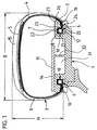
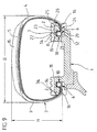
- Fig. 1 shows a vehicle wheel with pneumatic vehicle tires 3 and rim 1 with a ratio of maximum height H to maximum width B of the pneumatic vehicle tire H / B ⁇ 0.6.
- the Pneumatic vehicle tire 3 has a circumference of the tire and from the left bead area 6 of the pneumatic vehicle tire reaching to the right bead area 6, not shown in detail, Inner layer over which a carcass 4 radial design with, for example, one or two carcass plies is built up.
- the area of the tread is radially outside of the Carcass 4 a belt 5 of known type with, for example, two belt plies made in Rubber-embedded reinforcement, e.g. made of steel cord.
- the belt is enough over the entire circumference of the tire and extends in the axial direction from one tire shoulder area in the other.
- the steel cords run at an acute angle of, for example, 10-30 ° to the circumferential direction. Radially outside the belt layers, it is conceivable to have a belt bandage, not shown strength members running essentially to the circumferential direction, for example made of Nylon to wind up.
- the one-piece rim 1 is provided with one on each of its two axial end faces Ring chamber 10 arranged concentrically to the rim with a radially inner one Annular chamber wall 20, an axially inner annular chamber wall 21, a radially outer one Annular chamber wall 22 and an axially outer annular chamber wall 23 are formed in one piece.
- the annular chamber wall 23 delimits the radially inwardly directed rim flange 2. Axially to the inside between the rim flange 2 and the radially inner annular chamber wall 20 is one annular through opening 24 formed axially from the outside towards the annular chamber.
- the Rim flange 2 is on its radially inward side 25 from axially inward to axially flared on the outside and curved on its end face 26.
- a one piece Emergency running support ring 11 with an axial width E extends - as can be seen in FIG. 5 - concentric to the rim within the tire axially from the axial rim edge in the axial Direction to at least the center of the rim width F..
- the emergency run support ring 11 is radial formed on the outside with an emergency running surface 14.
- the emergency running surface 14 is profiled with in In the axial direction, circumferential ribs 34 arranged equidistant from one another Mistake.
- the support ring is supported in the axial region of the position of the annular chamber 10 the radially outer side of the rim flange 2, which the rim on the vehicle Limited on the outside of the vehicle, in the radial direction.
- the runflat surface extends one embodiment so far in the axial direction that the belt of the Belt edge made with 50 to 100% of its belt width W, for example 80%, axially the Emergency running surface covered.
- the vehicle pneumatic tire 3 engages with its lower side wall regions 16 horns 2 extending radially inward.
- the curvature of the end face 6 of the horn corresponds to that desired tire contour in the area of the horn.
- the bead area 6 is in each case with The bulge-shaped thickening 7 formed on the inside of the tire.
- the bead is with an elastic stretchy and elastic embedded in the carcass ply end compressible core 8 formed.
- the bead area fills 6 with positive locking to the axially inner annular chamber wall 21 and the radially outer Annulus 22 and the axially outer annulus 23 about 1/2 to 2/3 of Annulus.
- a filler ring 12 is radially form-fitting radially inside the bead to the bead area 6 radially outwards and radially inwards to the radially inner one Annular chamber wall 20 is formed, which extends in the axial direction from the annular chamber wall 10 over the entire axial extent of the bead region 6 through the ring opening 24 extends axially outward therethrough.
- the filler ring 12 is over the entire axial Extension area of the annular chamber and thus of the bead on its radially outer Shell cylindrical and axially outside the annular chamber parallel to the radially inner Side of the rim flange 25 flared.
- the filler ring 12 extends in the axial direction up to the axial position of the end face 26 of the rim flange.
- the bead is in the embodiment according to FIG. 1 with positive locking radially outward, axially inward and axially outward to the closed Annular chamber walls 22, 23, 21 and through the radial positive connection to the filler ring 12, the is in turn designed in a radial positive connection to the closed annular chamber wall 20, also to the annular chamber wall 20 in radial positive engagement.
- the annular chamber is completely filled with bead and filler ring.
- the lower side wall region 16 stands with the radially inner conical one Rim flange side 25 and with the correspondingly designed conical outer Mantle surface of the filler ring 12 also in the axial extent of the rim flange in full contact.
- the tire side wall lies in the region of the end face 26 of the horn 2 of the rim only under tension.
- the side wall area available for this purpose for the flexible curvature of the side wall extends from the shoulder area of the tread to the entire curved area of the end face 26. In the event of strong impacts, the tire side wall 9 lifts off in the area of the end face 26, forming a gap between the end face 26 and the tire side wall .
- the runflat support ring 11 extends over the entire circumferential area of the tire. At Sudden loss of pressure, the tire rests with its tread area on the Emergency tread 14 from. Premature destruction and detachment of the tire are avoided.
- the emergency run support ring 11 is made of elastic material - for example rubber or rubber-like plastic - formed into a layer 33 of parallel to each other arranged, tensile strength members is embedded.
- the elastic material of the Run-flat support ring is softer than the rubber material of the tread of the pneumatic vehicle tire.
- a full silica mixture of known type such as that made of solid rubber manufactured industrial tires is used.
- the strength members are monofilaments or cords made of tensile material, such as for Manufacture of tire belts is used.
- the strength members Monofilaments or cords made of aramid, steel or other suitable metallic or textile material.
- the strength members extend over the entire circumference of the Emergency running support ring at an angle between 0 ° and 30 ° to the circumferential direction.
- the layer 33 extends over a width G, which at least extends in the axial direction extends between the axial position of the belt edge and the center of the belt width.
- the Rim 1 is integral with a peripheral rib in the area of the center of the rim in its drop center 32 formed, which extends radially at least as far as the emergency running support body supporting rim flange on its radial outside.
- the emergency running support body 11 is supported with its left-hand side shown in FIG. 5 on the radial, cylindrical shape Outside of the left rim flange 2 and with its right side on the radial Outside of the circumferential rib 32 from friction
- the emergency running support ring radially on the position of Strength members a wide layer of strength members in one of the above Training opportunities embedded.
- the strength members of one layer are parallel or - if necessary to increase stiffness - not parallel to that of the first layer arranged. It can be useful to determine the direction of the slope of the reinforcement axial direction in one position opposite to the direction of the slope of the Form strength members of the other layer. It is the same in others Executions possible on the second layer one or more further layers of Embedding strength members in the support ring.
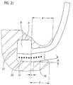
- FIG. 2a shows an enlarged detailed view of the outer edge region of the rim of FIG Fig. 1.
- Figure 2a it can be seen that the inside 25 of the rim flange of the Annular chamber wall 23 starting from the inclusion of an angle ⁇ to the wheel axis axially externally expanded up to the curved end face 26 of the rim flange 2.
- the radial outer lateral surface of the filling ring 12 is starting from the annular chamber wall 21 over the entire axial extent of the annular chamber to the annular chamber wall 23 and in an axial extension from the annular chamber up to an axial distance b
- Annular chamber wall 23 is cylindrical.
- the radially outer surface of the filler ring 12 is axial Direction to the outside parallel to the inside 25 of the rim flange also included of the angle ⁇ to the wheel axis axially outwardly flared.
- the Filling ring like the rim flange, still extends a distance a from Annular chamber wall 23 axially outwards.
- the filler ring 12 is axially displaceable on a cylindrical bearing surface 30 of the rim. Inside the ring chamber forms the Bearing surface 30, the radially inner annular chamber wall 20. The extends axially outward Bearing surface 30 to a distance d from the annular chamber wall 23.
- Axially outside of Distance d is the filler ring thickened radially inward to a shoulder and lies with this on a correspondingly trained shoulder of the rim.
- the distances a, b, d are chosen such that a is greater than d and d is greater than b.
- the angle ⁇ lies between 2 and 20 °. In the illustrated embodiment, it is approximately 10 °. In this way enclose the bead with its thickening 7 and the subsequent lower one Sidewall region 16 between the inner rim flange 25 and the filler ring the rim flange positively guided, whereby the anchoring of the tire in the rim is additionally secured.
- the filler ring is made of rubber or an elastic plastic with self-locking Surface trained. It is also conceivable to make the filler ring from a non-elastic Manufacture plastic or metal. If necessary in individual cases, it is also possible to Filling ring in the assembled state with its shoulder on the corresponding shoulder of the Also fix the rim axially, for example by screwing.
- the Bearing surface 30 extends axially to a distance c, which is less than or equal to that Distance a is from the annular chamber side wall 23 to the outside.
- the radially outer The lateral surface of the filling ring is from the axial position of the ring chamber side wall 23 also conical at the pitch angle ⁇ .
- the radial interior The outer surface of the filler ring is just like the correspondingly designed bearing surface 30 from an axial position at a distance c from the ring chamber side wall to the outside axially also conically expanded at an angle ⁇ to the wheel axis.
- the distance is c smaller a. Due to this conical design, the elastic filling ring is mounted in its Position additionally secured by axial positive locking.
- Fig2c is a filling ring as shown in Fig2b, but in the elastic rubber or Plastic material embedded essentially extending in the circumferential direction
- Strength member 17 contains.
- the strength members give the filler ring additional hold of the bearing surface 30.
- the strength members 17 can be arranged in a number of side by side Be circumferential wound tensile strength members.
- Another version is one or more strength members arranged side by side continuously helical around the axis of the filler ring from one axial end to the other axial end of the filler ring wrapped.
- the distances between the adjacent windings are equidistant. So far useful to achieve an even more secure fixation of the filling ring on the bearing surface 30, the distances can also be chosen differently.
- the strength members are Monofilaments or multifilaments made of steel. In another version they are Reinforcing textile monofilaments or multifilaments. It is also conceivable that To form reinforcement 17 from strips of fabric. The reinforcement of the filler ring 12 by strength members in the manner described is also in the embodiment of Fig.2a possible.
- Fig. 2d shows a further alternative embodiment, in which the filler ring also outside the Annular chamber is cylindrical.
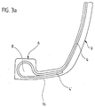
- the bead core 8 is made by embedding the core 8 into the carcass 4 by turning the carcass 4 around the core from the inside out, or as shown in the embodiment of Fig. 3b, anchored from the outside inwards.
- the Carcass 4 is tightly wrapped around core 8 and the cover 4 'is the same as in the other Embodiment of the envelope 4 '' following the core 8 in direct contact to the main part of the carcass.
- the core 8 is droplet-shaped to the point of contact between Cover and body of the carcass are tapered.
- To form the core 8 is an elastic rubber material with a Shore A hardness of 80 to 100, preferably 85 to 90 - in the exemplary embodiment of FIG.
- the core is extrusion by injection molding or comparatively known Techniques made.
- the rubber material of the bead is chosen so that the bead has the stated elongation and compression properties in the circumferential direction having.
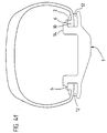
- abrasion between the rim flange and the lower side wall becomes undesirably large it is also possible, as shown by way of example in FIGS. 1 and 2a, between the rim flange and bead an additional strip 13 of abrasion-resistant material, for example of to form abrasion-resistant rubber or plastic.
- the abrasion-resistant strip can go right into the Ring chamber and be folded over there around the bead.
- the emergency running support surfaces 14 have one maximum outer diameter Dmax, the two rim flanges a minimum Inner diameter Dmin.
- the tire bead is in Fig.4a in the unexpanded and un-compressed state.
- Its outer diameter Dwa corresponds to the diameter of the radially outer annular chamber wall 22 and thus the outer diameter of the bead Dsa in its sitting position in the ring chamber.
- Its inner diameter Dwi corresponds to that Diameter of the radially outer circumferential surface of the filling ring 12 in the annular chamber and thus the inner diameter of the bead Dsi in its seating position in the annular chamber.
- Dmax is greater than Dsa
- Dsa is greater than Dsk
- Dsk is greater than Dmin
- Dmin is greater than Dsi.
- the emergency run support ring 11 is first concentrically in its sitting position on the Pushed and attached to the rim. Then the tire 3 is concentric to the rim on the Rim in the figures brought axially from the right. The left bulge turns against the elastic restoring forces of the bead stretched so far in the circumferential direction that the Inner diameter Dwi of the bead is larger than the maximum outer diameter Dmax Emergency running surfaces. Then, as shown in FIG. 4b, the tire 3 continues moved concentrically to the rim axially towards the rim, the left bead being retained its stretched condition with play to the emergency running support surfaces 14 axially over the rim and the support body is pushed.
- both beads are now against the elastic restoring forces in their circumferential length so far that the Outer diameter Dwa of the bead is smaller than the minimum rim flange diameter
- the beads are axially into the with play to the rim flange respective ring chamber introduced.
- the beads are set back in their circumferential length so far that they again assume unstretched and uncompressed condition.
- Dwi corresponds again Dsi
- Dwk also correspond to the middle one again Diameter Dsk of the core in its seating position in the ring chamber.
- the beads sit unstretched and undersized in the ring chamber. This state is shown in Fig.4d. As shown in FIG.
- a filler ring 12 is now between each axially outside lower sidewall region 16 of the tire and bearing surface 30 axially inserted so far that the annular chamber is completely filled by the bead and filler ring.
- the complete one Form-fit between the one-piece annular chamber and the bead is established.
- the filling ring is first removed axially outwards. After that the beads are compressed so far that they play with the rim flange from the ring chamber can be pulled. After resetting the circumferential length, a bead becomes so far stretched that it can be pulled axially from the rim with play to the emergency running support surfaces can.
- the diameter Dmax is, for example, 1.2 times larger than the inside diameter Dsi of the bead in the sitting position in the annular chamber and the minimum rim flange diameter is 1.025 times smaller than that Outside diameter Dsa of the bead in the sitting position in the ring chamber.
- Rubber material of the bead becomes a rubber material with an elasticity and with a compressibility chosen, such a stretching and compressing the bead in Circumferential direction allow the bead over the emergency support surface 14 and in the Annular chamber can be moved axially with play.
- a well-known Rubber material is used, the circumferential expansion of the bead by 25% and one Enable circumferential compression by 2.7%.
- the emergency support surfaces can also have a larger or smaller maximum Outside diameter Dmax according to the individually to be set Run-flat properties of a tire.
- the maximum diameter Dmax Run-flat support surfaces are ideally a factor of 1.1 to 1.2 for standard tires larger than the inner ring diameter Dsi of the bead core when the Vehicle wheel. In special cases, however, it can also be by a factor between 1.05 and 1.3 larger than the inner ring diameter Dsi of the bead core in the assembled state of the vehicle wheel.
- a rubber material is used as the rubber material of the bead with an extensibility and with a compressibility chosen, such an elongation and circumferentially upsetting the bead allow the bead to pass over the Emergency running support surface 14 and can be moved axially with play in the annular chamber.
- the bead which is not stretched when the vehicle wheel is assembled and is not compressed, designed such that it has an extensibility between 10 and 20% and a compressibility of 2.5 to 3.5% for standard tires and one in special cases Elasticity between 5 and 30% and compressibility between 1 and 5% having.
- the support body 35 is made of rubber, plastic or sheet metal in Lightweight construction or from another suitable material with low weight, with high radial compressive strength, high fatigue strength and good temperature stability formed and extends radially at least as far as the emergency running support body supporting rim flange extends radially on its radial outside. On its radial Outside it is cylindrical. It has a structure with several - eg with 3 - in Axial direction adjacent annular hollow chambers 36,37,38.
- the Emergency running support ring 11 is supported with its left side shown in FIG. 6 on the radial side Outside of the left rim flange 2 and with its right side on the radial Outside of the circumferential rib 32 from friction.
- the support ring is in the above embodiments on the Rim flange 2 and mounted on the support body 35 or on the peripheral rib 32.
- the Friction can occur, for example, by designing the emergency running support body with a press fit to the radial outside of the rim flange and the support body 35 or the peripheral rib 32 be generated
- the emergency run support ring also positively on the radial outside of the To attach rim flange 1.
- the emergency run support ring also positively on the radial outside of the To attach rim flange 1.
- FIG formed a circumferential groove 39 radially outside of the rim flange 1, into which form-fitting a circumferential rib correspondingly designed on the emergency running support ring 40 when the emergency support ring is pushed axially into its emergency support position engages with a snap.
- FIG. 8a and 8b are exemplary embodiments of the peripheral rib 40 and the Circumferential groove 39 shown.
- 8a, circumferential rib 40 and circumferential groove 39 have one trapezoidal cross-section
- FIG. 8b circumferential rib 40 and circumferential groove 39 have a triangular cross-section.
- Circumferential rib 40 and circumferential groove 39 have a rounded cross section.
- Fig. 7 shows an embodiment of the invention in which the rim with a flat bed 41st is formed, which extends radially at least as far with its radial surface, how the rim flange supporting the emergency running ring is radial on its radial outside extends.
- Left shoulder 42 the outer diameter is as large as the outer diameter of the radial surface of the left rim flange supporting the emergency run support body.
- the radially inner side of the Run-flat support ring is this outer contour of the rim flange and the flat bed Correspondingly designed so that the emergency support ring 11 from the left to the rim Assembly can be pushed on until it is on the inside of the emergency support ring trained stop shoulder in stop with the corresponding stop 42 of the Rim comes.
- the emergency running support ring 11 is supported with its left hand one shown in FIG. 7 Side on the radial outside of the left rim flange 2 and then on the radial outside of the flat bed 41 from friction.
- the emergency run support ring can be fixed on its axial Outside with a radially inward only over part of the circumference Directional nose 43 are provided, the axial sliding of the emergency support ring engages in a corresponding axial groove in the rim surface and the support ring in Circumferential direction.
- FIG. 9 shows an embodiment of a vehicle wheel according to FIG. 1, but with two Run-flat support rings.
- a one-piece emergency running support ring 11 with an axial width E extends axially from an axial concentric to the rim within the tire Rim edge in the axial direction to the center of the rims, but ends before reaching the center Rim width F.
- Each emergency run support ring 11 is radially outer with an emergency run surface 14 educated.
- the emergency running surface 14 is profiled with one another in the axial direction Equidistantly arranged circumferential ribs 34 are provided.
- Each support ring supports itself in the axial region of the position of the annular chamber 10 on the radially outer side of the associated rim flange 2, the rim on the vehicle to the outside of the vehicle limited, in the radial direction.
- the emergency running surface extends in one Execution so far in the axial direction that the belt from the belt edge with 10 to 40% of its belt width W, for example 30%, axially covers the emergency running surface.
- the profile ribs 34 of the support surface are in FIGS. 1 to 9 either not at all or shown with a substantially rectangular cross-sectional contour.
- Figures 10a and 10b show a cross section of the support ring in a sectional plane in which the axis of the Support ring is.
- the support ring 11 is on its radially outer surface with Circumferential direction of the support ring extending along the circumference side by side Equidistantly arranged parallel profile grooves 44, each between two adjacent profile grooves 44 parallel to them in the circumferential direction of the support ring Profile rib 34 extending over the circumference is formed.
- Profilrillengrund 47 rises the side wall 45 of the profile rib with inclusion an inclination angle ⁇ that changes in the radial direction with respect to the radial in the radial direction Direction outwards and then into the convexly curved radial outside 46 of the To pass profile rib 34.
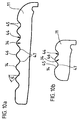
- An alternative contour course is the example of one wide support element shown in Fig.11. There the contour course corresponds axially Direction of semi-circles with the same radius for the convex semicircular curvature and for the concave semicircular curvature.
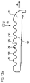
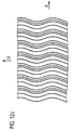
- Fig. 12 a, b, c shows the course of the example of an embodiment with the contour of Fig. 11 Profile grooves and profile ribs in the circumferential direction.
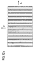
- FIGS. 12b and 12c Sectional view of the radial top view of the support ring shown in Fig.12a.
- the profile ribs and profile grooves of the support body are rectilinear in the circumferential direction running, shown in a different embodiment in FIG. 12c running in a wave shape.
- the Waveform is with equal amplitudes to the circumferential direction and along the circumference constant wavelength.
- webs 53 in are transverse to the profile grooves the profile grooves formed, each in a profile groove 44 from an adjacent Profile rib 34 extend to the other profile rib 34 and thus the two profile ribs 34 connect with each other and tie stiffening.
- the webs 53 extend into the Profile grooves above the base of the groove in the radial direction up to half the height h radial extension of the profile ribs 34 over the bottom of the profile groove.
- the webs 53 two Adjacent Rofilrillen are arranged offset to one another in the circumferential direction.
- the density of the profile ribs is Support element, which are each enclosed by two adjacent, profile grooves, in unloaded state of the support ring in the direction perpendicular to the profile rib course 0.4 to 1.5 ribs / cm.
- each profile rib of the support element is in Direction perpendicular to the profile rib course so that it extends from the a tread block member in this width direction of the tread Pneumatic vehicle tire to support the support element is designed in emergency running, deviates. This can be seen, for example, in FIG. 11, in which the Tread is also shown.
- the width of each profile rib of the support element in the direction perpendicular to the profile rib course measured from inflection point to inflection point is preferably less than half Extension of a tread block element in this direction of the tread Pneumatic vehicle tire to support it in the emergency or puncture run the support element is trained.
- the length h is the maximum radial Extension of the profile rib in the unloaded state of the support element starting from Groove base of the adjacent grooves up to the maximum radial extension of the profile rib in the Range between 1/3 and 2/3 of the radial extent T of the annular support body measured from its radial inside at the same axial position and the maximum radial extension of the profile rib is formed. This is for example in Fig. 11 shown.
Landscapes
- Engineering & Computer Science (AREA)
- Mechanical Engineering (AREA)
- Tires In General (AREA)
Abstract
wobei der ringförmige Stützkörper zumindest in seinem radial äußeren Bereich mit elastomerem Material und mit einer Profilierung ausgebildet ist, die parallele Profilrillen umfaßt, wobei zwischen jeweils zwei benachbarten Profilrillen eine Rrofilrippe eingeschlossen ist, die in ihrer Querschnittskontur in einer Schnittfläche senkrecht zum Rippenverlauf seitlich zu den sie einschließenden Profilrillen jeweils durch eine Seitenfläche und durch eine die beiden Seitenflächen in deren radialen Endbereich verbindende radiale Außenseite begrenzt wird,
dadurch gekennzeichnet,
daß die Querschnittskontur im unbelasteten Zustand im Bereich der radialen Außenseite konvex gekrümmt ausbebildet ist.
Description
wobei der ringförmige Stützkörper aus elastomerem Material und mit einer Profilierung ausgebildet ist, die parallele Profilrillen umfaßt, wobei zwischen jeweils zwei benachbarten Profilrillen eine Profilrippe eingeschlossen ist, die in ihrer Querschnittskontur in einer Schnittfläche senkrecht zum Rippenverlauf seitlich zu den sie einschließenden Profilrillen jeweils durch eine Seitenfläche und durch eine die beiden Seitenflächen in ihrem radialen Endbereich verbindende radiale Außenseite begrenzt wird, ist beispielsweise aus der EP 0 796 747 A1 bekannt.
- Fig. 1
- eine Querschnittsdarstellung eines erfindungsgemäßen Fahrzeugrades mit montiertem Fahrzeugreifen,
- Fig. 2
- Querschnittsdarstellungen von Ausführungsformen des Füllrings,
- Fig. 3
- Querschnittsdarstellungen von Ausführungsformen des Wulstbereichs,
- Fig. 4
- schematische Darstellung zur Erläuterung der Montage und der Demontage,
- Fig. 5
- Querschnittsdarstellung des Fahrzeugrades gemäß Fig.1 mit Aufbau des Notlaufstützrings
- Fig. 6
- Querschnittsdarstellung eines Fahrzeugrades gemäß Fig.1 in zweiter Ausführungsform
- Fig. 7
- Querschnittsdarstellung eines Fahrzeugrades gemäß Fig.1 in dritter Ausführungsform
- Fig. 8
- weitere Ausführungsformen einer formschlüssigen Fixierung des Notlaufstützrings
- Fig. 9
- Querschnittsdarstellung eines Fahrzeugrades gemäß Fig.1 mit alternativer Anordnung des Stützrings
- Fig.10
- erste erfindungsgemäße Ausführungsform der Querschnittskantur der Profilrippen und Profilrillen der radial äußeren Oberfläche des Stützrings
- Fig.11
- zweite erfindungsgemäße Ausführungsform der Profilrippen und Profilrillen der radial äußeren Oberfläche des Stützrings
- Fig.12
- Darstellungen zur Erläuterung des Umfangsverlaufs der Profilrippen und Profilrillen des Stützrings
- Fig.13
- Darstellungen einer Ausführung von Profilrippen und Profilrillen des Stützrings mit Stegen zur Anbindung benachbarter Profilrippen.
- 1
- Felge
- 2
- Felgenhorn
- 3
- Fahrzeugluftreifen
- 4
- Karkasse
- 5
- Gürtel
- 6
- Wulstbereich
- 7
- Verdickung
- 8
- Kern
- 9
- Seitenwand
- 10
- Ringkammer
- 11
- Notlaufstützring
- 12
- Füllring
- 13
- Abriebfester Streifen
- 14
- Notlauffläche
- 15
- Lauffläche
- 16
- unterer Seitenwandbereich
- 17
- Festigkeitsträger
- 18
- ringförmiges Stützelement
- 20
- Ringkammerwand
- 21
- Ringkammerwand
- 22
- Ringkammerwand
- 23
- Ringkammerwand
- 24
- Ringöffnung
- 25
- Innenseite des Felgenhorns
- 26
- Stirnfläche des Felgenhorns
- 30
- Lagerfläche
- 31
- Tiefbett
- 32
- Umfangsrippe
- 33
- Lage von Festigkeitsträgern
- 34
- Umfangsrippe
- 35
- Stützkörperring
- 36
- Hohlkammer
- 37
- Hohlkammer
- 38
- Hohlkammer
- 39
- Umfangsnut
- 40
- Umfangsnase
- 41
- Flachbett
- 42
- Anlageschulter
- 43
- Fixiernase
- 44
- Profilrille
- 45
- Seitenwand einer Profilrippe
- 46
- Radiale Außenseite einer Profilrippe
- 47
- Rillengrund
- 50
- Profilblockelement
- 51
- Profilrille
- 52
- Seitenwand des Profilblockelements
- 53
- Steg
Claims (27)
- Ringförmiger Stützkörper zum Stützen der Lauffläche eines Fahrzeugluftreifens in einem Fahrzeugrad im Notlauf bzw im Pannenlauf des Fahrzeugrades durch Abstützen des Laufstreifens auf der radialen Außenfläche des ringförmigen Stützkörpers,
wobei der ringförmige Stützkörper zumindest in seinem radial äußeren Bereich mit elastomerem Material und mit einer Profilierung ausgebildet ist, die parallele Profilrillen umfaßt, wobei zwischen jeweils zwei benachbarten Profilrillen eine Profilrippe eingeschlossen ist, die in ihrer Querschnittskontur in einer Schnittfläche senkrecht zum Rippenverlauf seitlich zu den sie einschließenden Profilrillen jeweils durch eine Seitenfläche und durch eine die beiden Seitenflächen in deren radialen Endbereich verbindende radiale Außenseite begrenzt wird,
dadurch gekennzeichnet,
daß die Querschnittskontur im unbelasteten Zustand im Bereich der radialen Außenseite konvex gekrümmt ausgebildet ist. - Ringförmiger Stützkörper gemäß den Merkmalen von Anspruch 1,
wobei die Profilrippe einschließenden Profilrillen in ihrem Rillengrund in einer Schnittfläche senkrecht zum Rillenverlauf in ihrer Querschnittskontur im unbelasteten Zustand des Stützkörpers konkav gekrümmt ausgebildet sind. - Ringförmiger Stützkörper gemäß den Merkmalen von Anspruch 1 oder 2,
wobei die die Profilrippe seitlich begrenzenden Seitenflächen in einer Schnittfläche senkrecht zum Rippenverlauf in radialer Richtung vom Rillengrund ausgehend nach radial außen zur radialen Außenseite der Profitrippe unter Einschluß eines Winkels zur Radialen zur Rippe hin geneigt ausgebildet sind, wobei der Winkel größer 0° und kleiner 45° beträgt. - Ringförmiger Stützkörper gemäß den Merkmalen von Anspruch 1, 2 oder 3,
wobei die die Profilrippe seitlich begrenzenden Seitenflächen in einer Schnittfläche senkrecht zum Rippenverlauf in radialer Richtung vom Rillengrund ausgehend nach radial außen zur radialen Außenseite der Profilrippe unter Einschluß eines sich in radialer Richtung verändernden Winkels zur Radialen zur Rippe geneigt ausgebildet ist; wobei die Neigung insbesondere mit einem Wendepunkt des Neigungsverlaufs ausgebildet ist. - Ringförmiger Stützkörper gemäß den Merkmalen von Anspruch 4,
wobei die Rrofilrippe einschließenden Profilrillen in ihrem Rillengrund in einer Schnittfläche senkrecht zum Rillenverlauf in ihrer Querschnittskontur im unbelasteten Zustand des Stützkörpers konkav gekrümmt ausgebildet sind und dieser Krümmungsverlauf im Bereich der Seitenfläche der Profilrippe stetig fortgeführt und an der Stelle des Wendepunktes in den konvexen Krümmungsverlauf der radialen Außenseite der Profilrippe stetig übergeht. - Ringförmiger Stützkörper gemäß den Merkmalen von einem oder mehreren der vorangegangenen Ansprüche,
wobei die konvexe und/oder die konkave Krümmung halbkreisförmig ausgebildet ist. - Ringförmiger Stützkörper gemäß den Merkmalen von einem oder mehreren der vorangegangenen Ansprüche,
wobei die konvexe und/oder die konkave Krümmung sinusförmig ausgebildet ist. - Ringförmiger Stützkörper gemäß den Merkmalen von einem oder mehreren der vorangegangenen Ansprüche,
wobei die Länge der maximalen radialen Erstreckung der Profilrippe im unbelasteten Zustand des Stützelements ausgehend vom Rillengrund der benachbarten Rillen bis zur maxialen radialen Erstreckung der Profilrippe im Bereich zwischen 1/3 und 2/3 der radialen Erstreckung des ringförmigen Stützkörpers gemessen von dessen radialer Innenseite im Bereich der Profilrippe und der maximalen radiale Erstreckung der Profilrippe ausgebildet ist. - Ringförmiger Stützkörper gemäß den Merkmalen von einem oder mehreren der vorangegangenen Ansprüche,
wobei die Breite jeder Profilrippe des Stützelements in Richtung senkrecht zum Profilrippenverlauf so ausgebildet ist, daß sie von der Erstreckung eines Profilblockelements in dieser Richtung des Laufstreifens eines Fahrzeugluftreifens zu dessen Abstützung im Not- bzw Pannenlauf das Stützelement ausgebildet ist, abweicht, - wobei sie insbesondere kleiner als die halbe Erstreckung eines Profilblockelements in dieser Richtung des Laufstreifens eines Fahrzeugluftreifens zu dessen Abstützung im Not- bzw Pannenlauf das Stützelement ausgebildet ist. - Ringförmiger Stützkörper gemäß den Merkmalen von einem oder mehreren der vorangegangenen Ansprüche,
wobei die Dichte der Profilrippen des Stützelements, die jeweils von zwei benachbarten Profilrillen eingeschlossen werden, im unbelasteten Zustand des Stützrings in Richtung senkrecht zum Profilrippenverlauf 0,4 bis 1,5 Rippen/cm beträgt. - Ringförmiger Stützkörper gemäß den Merkmalen von einem oder mehreren der vorangegangenen Ansprüche,
wobei die Profilrippen, die jeweils von zwei benachbarten Profilrillen eingeschlossen werden, in Umfangsrichtung des Stützkörpers ausgerichtet sind uns sich über den gesamten Umfang des Stützkörpers erstrecken. - Ringförmiger Stützkörper gemäß den Merkmalen von Anspruch 11,
wobei diese Profilrippen mit einem in Umfangsrichtung geradlinigen Verlauf ausgebildet sind. - Ringförmiger Stützkörper gemäß den Merkmalen von Anspruch 11,
wobei diese Profilrippen mit einem in Umfangsrichtung periodisch gekrümmten ― insbesondere wellenförmigen - Verlauf ausgebildet sind,
wobei Amplituden und/oder Frequenz der periodischen Krümmung vorzugsweise über den Umfang konstant sind. - Ringförmiger Stützkörper gemäß den Merkmalen von einem oder mehreren der vorangegangenen Ansprüche,
wobei an wenigstens einer Position im Rillenverlauf einer Profilrille des Stützkörpers im Rillengrund ein Steg ausgebildet ist, der sich quer zum Rillenverlauf erstreckt und zwei benachbarte Profilrippen des Stützkörpers miteinander verbindet und
wobei die maximale radiale Erstreckung des Profilstegs ausgehend vom Rillengrund der Rillen kleiner als die halbe maximale radialen Erstreckung der beiden Profilrippen im unbelasteten Zustand des Stützelements ausgehend vom Rillengrund der Rille bis zur maxialen radialen Erstreckung der Profilrippen im Bereich ausgebildet ist. - Fahrzeugrad mit Felge und schlauchlosem Luftreifen, bei dem auf der radial äußeren Mantelfläche der Felge ein Notlaufstützkörper zur Abstützung des Laufstreifens vom Fahrzeugluftreifen bei Not- bzw Pannenlauf angeordnet ist,
wobei der Notlaufstützkörper als ein ringförmiger Stützkörper gemäß den Merkmalen von einem oder mehreren der vorangegangenen Ansprüche ausgebildet ist. - Fahrzeugrad gemäß den Merkmalen von Anspruch 15,
wobei die axiale Position der in der radial äußeren Mantelfläche ausgebildeten Notlaufstützfläche zumindest teilweise der axialen Position eines in der Felge befestigten Wulstes entspricht. - Fahrzeugrad mit ― insbesondere einteiliger - Felge und schlauchlosem Luftreifen gemäß den Merkmalen von Anspruch 15 oder 16,mit an jeder Seitenwand des Luftreifens zur Innenseite des Luftreifens hin verdickt ausgebildetem Wulst zur Befestigung des Luftreifens an der Felge,mit wenigstens in einer axialen Stirnseite der Felge einstückig ausgebildeter Ringkammer mit einer radial inneren,einer radial äußeren, einer axial zur Felgenmitte hin inneren und einer axial zur Felgenaußenseite hin äußeren Ringkammerwand, wobei die nach axial außen zur Stirnseite der Felge hin ausgebildete Ringkammerwand im radial äußeren Bereich als ein radial nach innen gerichtetes Felgenhorn geschlossen ausgebildet und in ihrem radial inneren Bereich als ringförmige Öffnung ausgebildet ist,wobei ein Füllring innerhalb der Ringkammer auf der radial inneren Ringkammerwand radial fest gelagert ist,wobei sich die Seitenwand des Reifens zumindest im Betriebszustand des Fahrzeugrades von axial außen durch die Öffnung in der axial außen ausgebildeten Ringkammerwand hindurch nach innen erstreckt und der Wulst in der Ringkammer auf der radialen Außenseite des Füllrings radial fest gelagert ist und in formschlüssigem Berührkontakt zu wenigstens einer Ringkammerwand ausgebildet ist, sodaß der Wulst zu dieser Ringkammerwand und über den Füllring nach radial innen formschlüssig mit der einstückig ausgebildeten Ringkammer verbunden ist.
- Fahrzeugrad gemäß den Merkmalen von einem oder mehreren der Ansprüche 15 bis 17,mit an jeder Seitenwand des Luftreifens zur Innenseite des Luftreifens hin verdickt ausgebildetem in seiner Umfangslänge ― insbesondere
elastisch - veränderbarem Wulst zur Befestigung des Luftreifens an der Felge. - Fahrzeugrad gemäß den Merkmalen von einem der Ansprüche 15 bis 18,mit wenigstens in einer axialen Stirnseite der Felge einstückig ausgebildeter Ringkammer mit einer radial inneren,einer radial äußeren, einer axial zur Felgenmitte hin inneren und einer axial zur Felgenaußenseite hin äußeren Ringkammerwand, wobei die nach radial innen , nach radial außen und nach axial innen zur Felgenmitte hin ausgebildeten Ringkammerwände geschlossen und die nach axial außen zur Stirnseite der Felge hin ausgebildete Ringkammerwand im radial äußeren Bereich als ein radial nach innen gerichtetes Felgenhorn geschlossen ausgebildet und in ihrem radial inneren Bereich als ringförmige Öffnung ausgebildet ist,wobei sich die Seitenwand des Reifens zumindest im Betriebszustand des Fahrzeugrades von axial außen durch die Öffnung in der axial außen ausgebildeten Ringkammerwand hindurch nach innen erstreckt und der Wulst in der Ringkammer auf der radialen Außenseite des Füllrings radial fest gelagert ist und in formschlüssigem Berührkontakt wenigstens zur radial äußeren und zur axial äußeren geschlossenen Ringkammerwand ausgebildet ist, sodaß der Wulst wenigstens nach radial außen, nach axial außen, und über den Füllring nach radial innen formschlüssig mit der einstückig ausgebildeten Ringkammer verbunden ist,wobei der Wulst insbesondere über seine ganze axiale Erstreckung nach radial innen vollständig auf dem Füllring aufliegt und wobei insbesondere der Wulst und der Füllring die Ringkammer vollständig ausfüllen.
- Fahrzeugrad gemäß den Merkmalen von einem der Ansprüche 15 bis 19,
wobei wenigstens auf einem ― insbesondere auf beiden -axialen Seitenbereich der radial äußeren Mantelfläche der Felge eine Notlaufstützfläche ausgebildet ist, die sich insbesondere axial soweit nach innen erstreckt, daß der Gürtel in seiner axialen Randzonen von der Schulter mit 10 bis 40 % überdeckt ist. - Fahrzeugrad gemäß den Merkmalen von einem der Ansprüche 15 bis 19,
wobei auf einem axialen Seitenbereich der radial äußeren Mantelfläche der Felge eine Notlaufstützfläche ausgebildet ist, die sich insbesondere axial soweit nach innen erstreckt, daß der Gürtel in seiner axialen Randzonen von der Schulter mit 50 bis 100 % überdeckt ist. - Fahrzeugrad gemäß den Merkmalen von einem oder mehreren der Ansprüche 15 bis 21,
wobei im Wulst ein Gummikern integriert ausgebildet ist,
wobei der Gummikern insbesondere mit einer Shore -A- Härte aus dem Bereich von 80 bis 100, bevorzugt aus dem Bereich zwischen 85 bis 90 ausgebildet ist. - Fahrzeugrad gemäß den Merkmalen von einem oder mehreren der Ansprüche 15 bis 22,
wobei der Füllring mit seiner radial äußeren Mantelfläche in seiner Erstreckung innerhalb der Ringkammer im wesentlichen zylindrisch ausgebildet ist. - Fahrzeugrad gemäß den Merkmalen von einem oder mehreren der Ansprüche 15 bis 23,
bei dem der maximale Durchmesser der Notlaufstützflächen um einen Faktor zwischen 1,05 und 1,3 ― insbesondere zwischen 1,1 und 1,2 ― größer als der Innenringdurchmesser des Wulstkerns im montierten Zustand des Fahrzeugrades beträgt. - Fahrzeugrad gemäß den Merkmalen von einem oder mehreren der Ansprüche 15 bis 24,
wobei der Wulstkern eine Dehnbarkeit und/oder Stauchbarkeit von 5 bis 30 % - insbesondere 10 bis 20 % - aufweist. - Fahrzeugrad gemäß den Merkmalen von einem oder mehreren der Ansprüche 15 bis 25,
wobei der Wulstkern eine Dehnbarkeit von 5 bis 30 % -insbesondere 10 bis 20 % - und eine Stauchbarkeit von 1 bis 5% - insbesondere von 2,5 bis 3,5 % - aufweist und wobei der Wulstkern insbesondere im montierten Zustand des Fahrzeugrades ungedehnt und ungestaucht ist. - Fahrzeugrad gemäß den Merkmalen von einem oder mehreren der Ansprüche 15 bis 26,
wobei der Luftreifen mit seinem Wulst an der Felge befestigt ist und im unteren Seitenwandbereich an der Felge anliegt.
Applications Claiming Priority (2)
| Application Number | Priority Date | Filing Date | Title |
|---|---|---|---|
| DE1999143482 DE19943482B4 (de) | 1999-09-10 | 1999-09-10 | Ringförmiger Stützkörper zum Stützen der Lauffläche eines Fahrzeugluftreifens in einem Fahrzeugrad im Notlauf bzw. im Pannenlauf sowie Fahrzeugrad mit einem derartigen Stützkörper |
| DE19943482 | 1999-09-10 |
Publications (3)
| Publication Number | Publication Date |
|---|---|
| EP1083066A2 true EP1083066A2 (de) | 2001-03-14 |
| EP1083066A3 EP1083066A3 (de) | 2002-12-04 |
| EP1083066B1 EP1083066B1 (de) | 2006-03-08 |
Family
ID=7921607
Family Applications (1)
| Application Number | Title | Priority Date | Filing Date |
|---|---|---|---|
| EP20000119215 Expired - Lifetime EP1083066B1 (de) | 1999-09-10 | 2000-09-06 | Ringförmiger Notlaufstützkörper für Fahrzeugreifen, und Rad mit demselben |
Country Status (2)
| Country | Link |
|---|---|
| EP (1) | EP1083066B1 (de) |
| DE (2) | DE19943482B4 (de) |
Cited By (2)
| Publication number | Priority date | Publication date | Assignee | Title |
|---|---|---|---|---|
| CN111660737A (zh) * | 2020-07-14 | 2020-09-15 | 蒂龙科技发展(北京)有限公司 | 一种支撑带防脱堵塞支撑珠及爆胎应急安全装置 |
| CN113365854A (zh) * | 2019-03-19 | 2021-09-07 | 沈宗和 | 具备单一截面结构的无内胎轮胎总成 |
Families Citing this family (2)
| Publication number | Priority date | Publication date | Assignee | Title |
|---|---|---|---|---|
| DE102014211173B4 (de) | 2014-06-11 | 2023-09-28 | Bayerische Motoren Werke Aktiengesellschaft | Stützkörper für einen auf einer Felge montierbaren Luftreifen eines Fahrzeugs sowie Komplettrad mit einem solchen Stützkörper |
| DE102018112852A1 (de) * | 2018-05-29 | 2019-12-05 | Arnold Jäger Holding GmbH | Rad, insbesondere für landwirtschaftliche Maschinen, sowie Verfahren zum Herstellen eines Rades |
Family Cites Families (10)
| Publication number | Priority date | Publication date | Assignee | Title |
|---|---|---|---|---|
| US1932191A (en) * | 1931-01-27 | 1933-10-24 | Alvin H Shoemaker | Pneumatic tire and rim |
| DE1680402A1 (de) * | 1966-03-25 | 1970-07-09 | Augsburg Nuernberg Ag Zweignie | Notlaufring fuer Kraftfahrzeuge,insbesondere fuer schwere gelaendegaengige Kraftfahrzeuge |
| US4248286A (en) * | 1978-06-30 | 1981-02-03 | The Goodyear Tire & Rubber Company | Safety support assembly for pneumatic tires |
| DE8405217U1 (de) * | 1984-02-21 | 1985-05-30 | Uniroyal Englebert Reifen GmbH, 5100 Aachen | Fahrzeugrad |
| DE3410048A1 (de) * | 1984-03-19 | 1985-09-19 | Continental Gummi-Werke Ag, 3000 Hannover | Fahrzeugrad |
| DE3605803A1 (de) * | 1986-02-22 | 1987-01-02 | Daimler Benz Ag | Fahrzeugrad |
| FR2707923A1 (fr) * | 1993-07-19 | 1995-01-27 | Michelin & Cie | Dispositif de soutien d'une bande de roulement de pneumatique. |
| FR2746347A1 (fr) * | 1996-03-19 | 1997-09-26 | Michelin & Cie | Appui de securite en materiau elastomerique souple pour pneumatique |
| DE19837712A1 (de) * | 1998-08-20 | 2000-03-02 | Continental Ag | Fahrzeugrad |
| IT1304231B1 (it) * | 1998-10-23 | 2001-03-13 | Rino Rossi | Ruota per veicolo con mezzi anti - afflosciamento . |
-
1999
- 1999-09-10 DE DE1999143482 patent/DE19943482B4/de not_active Expired - Fee Related
-
2000
- 2000-09-06 EP EP20000119215 patent/EP1083066B1/de not_active Expired - Lifetime
- 2000-09-06 DE DE50012346T patent/DE50012346D1/de not_active Expired - Fee Related
Cited By (3)
| Publication number | Priority date | Publication date | Assignee | Title |
|---|---|---|---|---|
| CN113365854A (zh) * | 2019-03-19 | 2021-09-07 | 沈宗和 | 具备单一截面结构的无内胎轮胎总成 |
| CN113365854B (zh) * | 2019-03-19 | 2023-03-28 | 沈宗和 | 具备单一截面结构的无内胎轮胎总成 |
| CN111660737A (zh) * | 2020-07-14 | 2020-09-15 | 蒂龙科技发展(北京)有限公司 | 一种支撑带防脱堵塞支撑珠及爆胎应急安全装置 |
Also Published As
| Publication number | Publication date |
|---|---|
| EP1083066A3 (de) | 2002-12-04 |
| DE50012346D1 (de) | 2006-05-04 |
| DE19943482A1 (de) | 2001-03-22 |
| DE19943482B4 (de) | 2005-07-07 |
| EP1083066B1 (de) | 2006-03-08 |
Similar Documents
| Publication | Publication Date | Title |
|---|---|---|
| EP0860304A2 (de) | Luftbereiftes Fahrzeugrad | |
| DE2653658A1 (de) | Fahrzeugluftreifen mit plattfahreigenschaften | |
| DE19837740B4 (de) | Fahrzeugrad mit - insbesondere einteiliger - Felge und schlauchlosem Luftreifen, das für Notlauf geeignet ist | |
| DE60108496T2 (de) | Reifen mit einem Verstärkungselement in mindestens einer Seitenwand und montierte Reifen/Felge-Einheit | |
| EP0943465A1 (de) | Fahrzeugrad mit - insbesondere einteiliger - Felge und schlauchlosem Luftreifen, das insbesondere für Notlauf geeignet ist | |
| EP1083066B1 (de) | Ringförmiger Notlaufstützkörper für Fahrzeugreifen, und Rad mit demselben | |
| EP1104354A1 (de) | Fahrzeugrad | |
| DE10011673C2 (de) | Fahrzeugrad mit Felge und schlauchlosem Luftreifen und mit ringförmigen Notlaufstützkörper | |
| DE19927333C2 (de) | Fahrzeugrad mit Felge und schlauchlosem Luftreifen, das für Notlauf geeignet ist | |
| DE19927336C2 (de) | Fahrzeugrad Felge und schlauchlosem Luftreifen, das für Notlauf geeignet ist | |
| DE19927332C2 (de) | Fahrzeugrad mit Felge und schlauchlosem Luftreifen, das für Notlauf geeignet ist | |
| DE19927334C2 (de) | Fahrzeugrad mit Felge und schlauchlosem Luftreifen, das für Notlauf geeignet ist | |
| DE10011647A1 (de) | Fahrzeugrad mit Felge und schlauchlosem Luftreifen und mit ringförmigen Notlaufstützkörper | |
| DE19927335C2 (de) | Fahrzeugrad mit Felge und schlauchlosem Luftreifen, das für Notlauf geeignet ist | |
| EP1066986B1 (de) | Felge eines Fahrzeugrades für schlauchlose Luftreifen mit auf der radial äusseren Mantelfläche der Felge ausgebildeter Notlaufstützfläche | |
| DE19942549A1 (de) | Füllring zum Füllen eines radialen ringförmigen Spaltbereichs zwischen der radial inneren Wand einer Ringkammer in der Stirnfläche einer Felge eines Fahrzeugrads mit Felge und schlauchlosem Luftreifen und ...... | |
| DE19959460C2 (de) | Füllring eines Fahrzeugrades mit Felge und schlauchlosem Luftreifen sowie Fahrzeugrad mit einem derartigen Füllring | |
| DE19959461C2 (de) | Füllring eines Fahrzeugrades mit Felge und schlauchlosem Luftreifen sowie Fahrzeugrad mit einem derartigen Füllring | |
| EP0976582A2 (de) | Fahrzeugrad mit - insbesondere einteiliger - Felge und mit einem - insbesondere schlauchlosen - Luftreifen mit zwei Reifenseitenwänden | |
| DE10014784C2 (de) | Fahrzeugrad mit Felge, schlauchlosem Luftreifen und mit ringförmigem Notlaufstützkörper | |
| DE19855519A1 (de) | Fahrzeugrad mit - insbesondere einteiliger - Felge und schlauchlosem Luftreifen, das insbesondere für Notlauf geeignet ist, und eine Felge zum Einsatz in einem solchen Fahrzeugrad | |
| DE19844368C2 (de) | Fahrzeugrad mit insbesondere einteiliger Felge und schlauchlosem Luftreifen, das insbesondere für Notlauf geeignet ist, und ein Verfahren zu seiner Montage |
Legal Events
| Date | Code | Title | Description |
|---|---|---|---|
| PUAI | Public reference made under article 153(3) epc to a published international application that has entered the european phase |
Free format text: ORIGINAL CODE: 0009012 |
|
| AK | Designated contracting states |
Kind code of ref document: A2 Designated state(s): AT BE CH CY DE DK ES FI FR GB GR IE IT LI LU MC NL PT SE |
|
| AX | Request for extension of the european patent |
Free format text: AL;LT;LV;MK;RO;SI |
|
| PUAL | Search report despatched |
Free format text: ORIGINAL CODE: 0009013 |
|
| AK | Designated contracting states |
Kind code of ref document: A3 Designated state(s): AT BE CH CY DE DK ES FI FR GB GR IE IT LI LU MC NL PT SE |
|
| AX | Request for extension of the european patent |
Free format text: AL;LT;LV;MK;RO;SI |
|
| 17P | Request for examination filed |
Effective date: 20030604 |
|
| AKX | Designation fees paid |
Designated state(s): DE FR GB IT |
|
| 17Q | First examination report despatched |
Effective date: 20040513 |
|
| GRAP | Despatch of communication of intention to grant a patent |
Free format text: ORIGINAL CODE: EPIDOSNIGR1 |
|
| GRAS | Grant fee paid |
Free format text: ORIGINAL CODE: EPIDOSNIGR3 |
|
| GRAA | (expected) grant |
Free format text: ORIGINAL CODE: 0009210 |
|
| AK | Designated contracting states |
Kind code of ref document: B1 Designated state(s): DE FR GB IT |
|
| PG25 | Lapsed in a contracting state [announced via postgrant information from national office to epo] |
Ref country code: GB Free format text: LAPSE BECAUSE OF FAILURE TO SUBMIT A TRANSLATION OF THE DESCRIPTION OR TO PAY THE FEE WITHIN THE PRESCRIBED TIME-LIMIT Effective date: 20060308 Ref country code: IT Free format text: LAPSE BECAUSE OF FAILURE TO SUBMIT A TRANSLATION OF THE DESCRIPTION OR TO PAY THE FEE WITHIN THE PRESCRIBED TIME-LIMIT;WARNING: LAPSES OF ITALIAN PATENTS WITH EFFECTIVE DATE BEFORE 2007 MAY HAVE OCCURRED AT ANY TIME BEFORE 2007. THE CORRECT EFFECTIVE DATE MAY BE DIFFERENT FROM THE ONE RECORDED. Effective date: 20060308 |
|
| REG | Reference to a national code |
Ref country code: GB Ref legal event code: FG4D Free format text: NOT ENGLISH |
|
| REF | Corresponds to: |
Ref document number: 50012346 Country of ref document: DE Date of ref document: 20060504 Kind code of ref document: P |
|
| GBV | Gb: ep patent (uk) treated as always having been void in accordance with gb section 77(7)/1977 [no translation filed] |
Effective date: 20060308 |
|
| PLBE | No opposition filed within time limit |
Free format text: ORIGINAL CODE: 0009261 |
|
| STAA | Information on the status of an ep patent application or granted ep patent |
Free format text: STATUS: NO OPPOSITION FILED WITHIN TIME LIMIT |
|
| 26N | No opposition filed |
Effective date: 20061211 |
|
| EN | Fr: translation not filed | ||
| PGFP | Annual fee paid to national office [announced via postgrant information from national office to epo] |
Ref country code: DE Payment date: 20070824 Year of fee payment: 8 |
|
| PG25 | Lapsed in a contracting state [announced via postgrant information from national office to epo] |
Ref country code: FR Free format text: LAPSE BECAUSE OF FAILURE TO SUBMIT A TRANSLATION OF THE DESCRIPTION OR TO PAY THE FEE WITHIN THE PRESCRIBED TIME-LIMIT Effective date: 20070309 |
|
| PG25 | Lapsed in a contracting state [announced via postgrant information from national office to epo] |
Ref country code: FR Free format text: LAPSE BECAUSE OF FAILURE TO SUBMIT A TRANSLATION OF THE DESCRIPTION OR TO PAY THE FEE WITHIN THE PRESCRIBED TIME-LIMIT Effective date: 20060308 |
|
| PG25 | Lapsed in a contracting state [announced via postgrant information from national office to epo] |
Ref country code: DE Free format text: LAPSE BECAUSE OF NON-PAYMENT OF DUE FEES Effective date: 20090401 |