EP1083082A2 - Dispositif pour monter et démonter un siège de véhicule - Google Patents
Dispositif pour monter et démonter un siège de véhicule Download PDFInfo
- Publication number
- EP1083082A2 EP1083082A2 EP00110890A EP00110890A EP1083082A2 EP 1083082 A2 EP1083082 A2 EP 1083082A2 EP 00110890 A EP00110890 A EP 00110890A EP 00110890 A EP00110890 A EP 00110890A EP 1083082 A2 EP1083082 A2 EP 1083082A2
- Authority
- EP
- European Patent Office
- Prior art keywords
- pair
- mounting
- dismounting
- vehicle seat
- roller
- Prior art date
- Legal status (The legal status is an assumption and is not a legal conclusion. Google has not performed a legal analysis and makes no representation as to the accuracy of the status listed.)
- Withdrawn
Links
- 230000037431 insertion Effects 0.000 claims description 5
- 238000003780 insertion Methods 0.000 claims description 5
- 206010039203 Road traffic accident Diseases 0.000 description 2
- 238000010276 construction Methods 0.000 description 1
- 230000007547 defect Effects 0.000 description 1
Images



Classifications
-
- B—PERFORMING OPERATIONS; TRANSPORTING
- B60—VEHICLES IN GENERAL
- B60N—SEATS SPECIALLY ADAPTED FOR VEHICLES; VEHICLE PASSENGER ACCOMMODATION NOT OTHERWISE PROVIDED FOR
- B60N2/00—Seats specially adapted for vehicles; Arrangement or mounting of seats in vehicles
- B60N2/02—Seats specially adapted for vehicles; Arrangement or mounting of seats in vehicles the seat or part thereof being movable, e.g. adjustable
- B60N2/04—Seats specially adapted for vehicles; Arrangement or mounting of seats in vehicles the seat or part thereof being movable, e.g. adjustable the whole seat being movable
- B60N2/06—Seats specially adapted for vehicles; Arrangement or mounting of seats in vehicles the seat or part thereof being movable, e.g. adjustable the whole seat being movable slidable
- B60N2/08—Seats specially adapted for vehicles; Arrangement or mounting of seats in vehicles the seat or part thereof being movable, e.g. adjustable the whole seat being movable slidable characterised by the locking device
-
- B—PERFORMING OPERATIONS; TRANSPORTING
- B60—VEHICLES IN GENERAL
- B60N—SEATS SPECIALLY ADAPTED FOR VEHICLES; VEHICLE PASSENGER ACCOMMODATION NOT OTHERWISE PROVIDED FOR
- B60N2/00—Seats specially adapted for vehicles; Arrangement or mounting of seats in vehicles
- B60N2/005—Arrangement or mounting of seats in vehicles, e.g. dismountable auxiliary seats
- B60N2/015—Attaching seats directly to vehicle chassis
- B60N2/01508—Attaching seats directly to vehicle chassis using quick release attachments
- B60N2/01516—Attaching seats directly to vehicle chassis using quick release attachments with locking mechanisms
- B60N2/01583—Attaching seats directly to vehicle chassis using quick release attachments with locking mechanisms locking on transversal elements on the vehicle floor or rail, e.g. transversal rods
-
- B—PERFORMING OPERATIONS; TRANSPORTING
- B60—VEHICLES IN GENERAL
- B60N—SEATS SPECIALLY ADAPTED FOR VEHICLES; VEHICLE PASSENGER ACCOMMODATION NOT OTHERWISE PROVIDED FOR
- B60N2/00—Seats specially adapted for vehicles; Arrangement or mounting of seats in vehicles
- B60N2/005—Arrangement or mounting of seats in vehicles, e.g. dismountable auxiliary seats
- B60N2/015—Attaching seats directly to vehicle chassis
- B60N2/01508—Attaching seats directly to vehicle chassis using quick release attachments
- B60N2/01591—Attaching seats directly to vehicle chassis using quick release attachments with wheels coupled to the seat
Definitions
- the present invention relates to a device for mounting and dismounting a vehicle seat, and more particularly, the present invention relates to a device for mounting and dismounting a vehicle seat, which enables the vehicle seat to be easily mounted to and dismounted from a floor panel of a vehicle as occasion demands, thereby, in the case of dismounting the vehicle seat from the floor panel of the vehicle, allowing the vehicle seat to be conveniently moved to and stored in a desired place in a state wherein a seat back of the vehicle seat is folded to a seat cushion of the vehicle seat.
- a vehicle seat having a seat cushion and a seat back is mounted onto a floor panel which delimits a lower surface of a passenger compartment, thereby to render comfortableness to passengers.
- the conventional vehicle seat suffers from defects in that, since the vehicle seat is fixedly secured to the floor panel, in the case of carrying bulky cargo, it is inconvenient to load the bulky cargo into the passenger compartment. Further, when it is required to utilize a portion of the passenger compartment as a freight loading space, space utilization efficiency is deteriorated due to the fixedly secured vehicle seat.
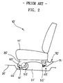
- FIGs. 1 and 2 a device for mounting and dismounting a vehicle seat, a typical example of which is illustrated in FIGs. 1 and 2, is disclosed in the art.
- a pair of supporting members 20' are secured to a lower surface of a seat cushion 11' of a vehicle seat 10' at both sides of the lower surface, respectively.
- a pair of rollers 50' are rotatably arranged adjacent to front and rear ends of each supporting member 20', respectively, in such a manner that they project downward beyond a lower end surface of the supporting member 20'.
- a first locker 60' is fastened to the front end of the supporting member 20' and is formed with an engaging groove 61'.
- a first striker 40' which is disposed at a front end of a recess 31' defined in the floor panel 30', can be engaged into and disengaged from the engaging groove 61' of the first locker 60'.
- a second locker 70' is fastened to the rear end of the supporting member 20'. The second locker 70' can be locked to and unlocked from a second striker 40' which is disposed at a rear end of the recess 31' defined in the floor panel 30'.
- the second locker 70' can be pivoted about a shaft by the manipulation of a lever 71'.
- the first striker 40' which is disposed at the front end of the recess 31' defined in the floor panel 30', is first engaged into the engaging groove 61' of the first locker 60' which is fastened to the front end of the supporting member 20'.
- the vehicle seat 10' is fixedly secured to an upper surface of the floor panel 30'.
- the lever 71' is first pulled to unlock the second locker 70' from the second striker 40'. Then, by raising the vehicle seat 10' upward to completely disengage the first striker 40' from the engaging groove 61' of the first locker 60', the vehicle seat 10' can be moved to a desired place using the rollers 50'.
- the dismounted vehicle seat 10' can be moved by being pushed in a state wherein the rollers 50', which are arranged adjacent to front and rear ends of the pair of supporting members 20', are brought into contact with the upper surface of the floor panel 30', it is convenient for a person to remove the vehicle seat 10' from the passenger compartment and move and store in a desired place.
- the conventional device for mounting and dismounting a vehicle seat still encounters with a problem in that, because the first locker 60' simply serves as a rotation support shaft in a state wherein the first striker 40' which is disposed at the front end of the recess 31', is engaged into the engaging groove 61' formed in the first locker 60' which is fastened to the front end of the supporting member 20', if impact is applied to the vehicle due to a vehicular accident while the vehicle seat 10' is mounted to the floor panel 30' of the vehicle, the second locker 70' is easily unlocked from the second striker 40' which is disposed at the rear end of the recess 31', whereby the likelihood for a passenger seating on the vehicle seat 10' to be severely injured is increased.
- an object of the present invention is to provide a device for mounting and dismounting a vehicle seat, which enables the vehicle seat to be securely locked to strikers in the case of mounting the vehicle seat to a floor panel of a vehicle and at the same time to be quickly and conveniently unlocked from the strikers in the case of dismounting the vehicle seat from the floor panel of the vehicle as occasion demands.
- a device for mounting and dismounting a vehicle seat the device being arranged on a pair of supporting members separately secured to a lower surface of a seat cushion of the vehicle seat thereby to allow the vehicle seat to be mounted to and dismounted from a floor panel of a vehicle as occasion demands, the device being characterized by: a pair of first mounting and dismounting sections each having a first locker which is connected to a front catch-release lever in a manner such that the first locker is able to be locked to and unlocked from a front striker which is disposed in a front recess defined in the floor panel of the vehicle, the front catch-release lever being elastically supported by a first spring; a pair of second mounting and dismounting sections having a pair of second lockers, respectively, which are connected with each other by a rear catch-release lever in a manner such that each of the pair of second lockers is able to be locked to and unlocked from a rear striker which is disposed in a
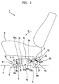
- a device for mounting and dismounting a vehicle seat in accordance with an embodiment of the present invention, is arranged on a pair of supporting members 3 which are separately secured to a lower surface of a seat cushion 2 of a vehicle seat 1, thereby to allow the vehicle seat 1 to be mounted to and dismounted from a floor panel 4 of a vehicle as occasion demands.
- the device includes a pair of first mounting and dismounting sections 10, a pair of second mounting and dismounting sections 14, and a pair of roller sections 19.
- Each of the pair of first mounting and dismounting sections 10 has a first locker 9 which is connected to a front catch-release lever 8 in a manner such that the first locker 9 is able to be locked to and unlocked from a front striker 6a which is disposed in a front recess 5 defined in the floor panel 4 of the vehicle.
- the front catch-release lever 8 is elastically supported by a first spring 7.
- the pair of second mounting and dismounting sections 14 have a pair of second lockers 13, respectively, which are connected with each other by a rear catch-release lever 12 in a manner such that each of the pair of second lockers 13 is able to be locked to and unlocked from a rear striker 6b which is disposed in a rear recess 5 defined in the floor panel 4 of the vehicle.
- the rear catch-release lever 12 is elastically supported by a second spring 11 and has a rod-shaped configuration.
- Each of the pair of roller sections 19 is located outside the first and second mounting and dismounting sections 10 and 14 at a side of the seat cushion 2 and includes front and rear roller plates 17a and 17b which have front and rear rollers 18a and 18b rotatably coupled thereto, respectively.
- the front and rear roller plates 17a and 17b are connected with each other by a link 16 in a manner such that they are able to be pivoted by manipulating a roller operating lever 15.
- the pair of first mounting and dismounting sections 10 are arranged at front ends of the pair of supporting members 3, respectively.
- the pair of supporting members 3 are secured to the lower surface of the seat cushion 2 of the vehicle seat 1 in a manner such that they are spaced apart by a predetermined distance. Because the pair of first mounting and dismounting sections 10 have the same construction, hereinafter, only one of the pair of first mounting and dismounting sections 10 will be mainly described in detail.
- the first mounting and dismounting section 10 has the first locker 9.
- the first locker 9 is rotated about a front center shaft 20 by the manipulation of the front catch-release lever 8 in such a manner that it is locked to and unlocked from the front striker 6a. If external force applied to the front catch-release lever 8 is removed, the first locker 9 is returned to its original position by the elastic force of the first spring 7.
- the pair of second mounting and dismounting sections 14 are arranged at rear ends of the pair of supporting members 3, respectively.
- the pair of second mounting and dismounting sections 14 are connected with each other by the single rear catch-release lever 12 which has the rod-shaped configuration, thereby to be simultaneously operated.
- the second locker 13 is pivoted about a rear center shaft 21 in such a manner that it is locked to and unlocked from the rear striker 6b. If external force applied to the rear catch-release lever 12 is removed, the second locker 13 is returned to its original position by the elastic force of the second spring 11.
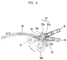
- the front and rear rollers 18a and 18b are rotatably coupled to the front and rear roller plates 17a and 17b, respectively.
- the front and rear roller plates 17a and 17b are integrally connected with each other by the link 16.
- the front and rear rollers 18a and 18b can be freely rotated about front and rear supporting shafts 31, respectively.
- a stopper bracket 23 which is formed with upper and lower stopper grooves 22a and 22b and a guide bracket 25 which is formed with a first guide slot 24a, are pivotally connected with each other by a pivot shaft 26 while they sandwich the rear roller plate 17b therebetween.
- the rear roller plate 17b to which the rear roller 18b is rotatably coupled, is formed adjacent to a rear end thereof with a stopper pin insertion slot 27.
- the stopper pin insertion slot 27 has a moving slot portion 27a and an operating slot portion 27b which is substantially perpendicular to and communicated with the moving slot portion 27a.
- a stopper pin 28 which is supported by the roller operating lever 15, is inserted through the stopper pin insertion slot 27.
- the roller operating lever 15 is connected with the rear roller plate 17b via the stopper pin 28.
- the roller operating lever 15 is formed with a second guide slot 24b.
- a guide pin 29 is inserted through the first guide slot 24a which is defined in the guide bracket 25 and the second guide slot 24b which is defined in the roller operating lever 15 in a manner such that it can be moved forward or rearward along the slots 24a and 24b.
- a third spring 30 between the stopper pin 28 and the pivot shaft 26 which is mounted at a rotating point of the rear roller plate 17b and the stopper bracket 23, there is disposed a third spring 30.
- the upper and lower stopper grooves 22a and 22b of the stopper bracket 23 are defined in a manner such that a length of the upper stopper groove 22a is smaller than that of the lower stopper groove 22b, thereby enabling the stopper pin 28 to be moved with reduced force when manipulating the roller operating lever 15.
- the vehicle seat 1 can be rotated in the counterclockwise direction about the front striker 6a.
- a seat back of the vehicle seat 1 is first folded to the seat cushion 2, and then the combination of the seat back and the seat cushion 2 is double folded by being rotated about the front striker 6a by a predetermined angle, for example, by 90°.
- the first lockers 9 of the pair of first mounting and dismounting sections 10 are structured so that they can be continuously and reliably maintained in the locked state while they are rotated about the front striker 6a. If the front and rear rollers 18a and 18b of the roller section 19, which are integrally connected with each other by the link 16, are detached from the upper surface of the floor panel 4, the rear roller plate 17b is moved upward about the stopper pin 28 by an angle (about 45° ) of the arc-shaped moving slot portion 27a which is defined adjacent to the rear end of the rear roller plate 17b. According to this, the rear roller 18b which is rotatably coupled to a front end of the rear roller plate 17b, is moved downward about the pivot shaft 26 by its own weight. Hence, the front and rear rollers 18a and 18b are located in a manner such that they can be simultaneously operated via the link 16.
- the front catch-release lever 8 which is provided to the first mounting and dismounting section 10 is manipulated by being pressed downward, the first locker 9 is unlocked from the front striker 6a, and thereby, the vehicle seat 1 can be completely dismounted from the floor panel 4 to be freely moved. If external force which is applied to the front catch-release lever 8 is removed, the first mounting and dismounting section 10 is returned to its original position about the front center shaft 20 by the elastic force of the first spring 7.
- the above-described dismounting operations are reversely performed.
- the first locker 9 of the first mounting and dismounting section 10 is first locked to the front striker 6a.
- the rollers 18a and 18b are moved toward the seat cushion 2 by manipulating the roller operating lever 15, and the second locker 13 of the second mounting and dismounting section 14 is locked to the rear striker 6b.
- the vehicle seat 1 can be securely mounted again to the floor panel 4.
- the device for mounting and dismounting a vehicle seat provides advantages in that, since first and second mounting and dismounting sections arranged below a seat cushion of the vehicle seat are detachably locked to strikers disposed on a floor panel of a vehicle, it is possible to dismount the vehicle seat from the floor panel of the vehicle and utilize a volume occupied by the vehicle seat as a freight loading space, whereby bulky cargo can be loaded into the freight loading space.
Landscapes
- Engineering & Computer Science (AREA)
- Aviation & Aerospace Engineering (AREA)
- Transportation (AREA)
- Mechanical Engineering (AREA)
- Seats For Vehicles (AREA)
Applications Claiming Priority (2)
| Application Number | Priority Date | Filing Date | Title |
|---|---|---|---|
| KR9936507 | 1999-08-31 | ||
| KR1019990036507A KR100310014B1 (ko) | 1999-08-31 | 1999-08-31 | 차량용 시트의 탈장착장치 |
Publications (2)
| Publication Number | Publication Date |
|---|---|
| EP1083082A2 true EP1083082A2 (fr) | 2001-03-14 |
| EP1083082A3 EP1083082A3 (fr) | 2002-04-03 |
Family
ID=19609363
Family Applications (1)
| Application Number | Title | Priority Date | Filing Date |
|---|---|---|---|
| EP00110890A Withdrawn EP1083082A3 (fr) | 1999-08-31 | 2000-05-23 | Dispositif pour monter et démonter un siège de véhicule |
Country Status (3)
| Country | Link |
|---|---|
| US (1) | US6196611B1 (fr) |
| EP (1) | EP1083082A3 (fr) |
| KR (1) | KR100310014B1 (fr) |
Cited By (3)
| Publication number | Priority date | Publication date | Assignee | Title |
|---|---|---|---|---|
| WO2002020301A1 (fr) * | 2000-09-11 | 2002-03-14 | Oy Tamlans Ab | Mecanisme de montage rapide et siege de vehicule |
| EP1215075A1 (fr) * | 2000-12-18 | 2002-06-19 | Kia Motors Corporation | Déverrouillage/verrouillage d'un siège de véhicule au plancher d'un véhicule |
| DE102004035478A1 (de) * | 2004-07-14 | 2006-02-16 | Volkswagen Ag | Entriegelungsmechanismus für ein Befestigungssystem einer Sitzreihe eines Kombifahrzeuges |
Families Citing this family (14)
| Publication number | Priority date | Publication date | Assignee | Title |
|---|---|---|---|---|
| US6375245B1 (en) * | 2000-10-09 | 2002-04-23 | Johnson Controls Technology Company | Vehicle seating system having chuck reducing apparatus |
| KR100412469B1 (ko) * | 2001-07-02 | 2003-12-31 | 현대자동차주식회사 | 자동차용 시트의 탈부착 장치 |
| FR2829439B1 (fr) * | 2001-09-07 | 2004-01-16 | Faurecia Sieges Automobile | Pietement de siege de vehicule, siege comportant un tel pietement et ensemble d'assise comportant un tel siege |
| KR20030024502A (ko) * | 2001-09-18 | 2003-03-26 | 기아자동차주식회사 | 자동차의 더블 폴딩식 시트 |
| KR100461163B1 (ko) * | 2001-09-18 | 2004-12-09 | 기아자동차주식회사 | 2단 접철식 시트조립체의 자동잠금장치 |
| KR20030038986A (ko) * | 2001-11-09 | 2003-05-17 | 기아자동차주식회사 | 차량용 시트 탈착 장치 |
| US6655702B2 (en) | 2002-01-15 | 2003-12-02 | Patent Holding Company | Combination vehicle passenger seat/child stroller |
| KR100461257B1 (ko) * | 2002-04-18 | 2004-12-10 | 기아자동차주식회사 | 차량의 탈착식 시트 |
| KR100520774B1 (ko) * | 2003-09-30 | 2005-10-12 | 기아자동차주식회사 | 차량의 탈착식 시트 |
| KR100604737B1 (ko) * | 2004-07-13 | 2006-07-31 | 대원산업 주식회사 | 차량용 착탈식 시트장치 |
| US7434862B2 (en) * | 2005-10-11 | 2008-10-14 | Bae Industries, Inc. | Combination front and rear floor latch assembly for selective forward tumbling and removal of a rear row vehicle seat |
| US7500707B2 (en) * | 2005-10-11 | 2009-03-10 | Bae Industries, Inc. | Removable vehicle seat |
| US7914077B2 (en) * | 2009-06-18 | 2011-03-29 | Toyota Motor Engineering & Manufacturing North America, Inc. | Single motion load bearing release handle |
| CN109606213B (zh) * | 2019-01-21 | 2024-06-07 | 广西双英集团股份有限公司 | 一种带一键解锁翻转机构的座椅 |
Family Cites Families (11)
| Publication number | Priority date | Publication date | Assignee | Title |
|---|---|---|---|---|
| US4872693A (en) * | 1987-01-23 | 1989-10-10 | Gordon Kennel | Combination infant seat and stroller |
| US4874182A (en) * | 1987-12-28 | 1989-10-17 | Wade Parker | Stroller apparatus for juvenile car seat |
| US4902026A (en) * | 1989-02-16 | 1990-02-20 | Maldonado Robert L | Convertible car seat apparatus |
| US5238285A (en) * | 1992-07-16 | 1993-08-24 | Douglas & Lomason Company | Folding vehicle bedseat |
| US5372398A (en) * | 1993-04-02 | 1994-12-13 | Chrysler Corporation | Vehicle seat assembly with retracting latch/engaging roller seat-to-floor lock |
| US5474311A (en) * | 1994-02-25 | 1995-12-12 | Invenio Corporation | Vehicle bench seat retractable wheel carriage |
| JP3500717B2 (ja) * | 1994-08-31 | 2004-02-23 | アイシン精機株式会社 | 車両用シート装置 |
| US5547242A (en) * | 1995-02-10 | 1996-08-20 | Atoma International, Inc. | Latch/unlatch indicator for vehicle seat-to floor latch mechanism |
| JP3228406B2 (ja) * | 1997-03-07 | 2001-11-12 | ジョンソン コントロールズ オートモーティブ システムズ株式会社 | 車両用シートの脱着機構 |
| JP4134364B2 (ja) * | 1997-12-26 | 2008-08-20 | アイシン精機株式会社 | 車両用シート構造 |
| US6036252A (en) * | 1998-01-20 | 2000-03-14 | Lear Corporation | Automotive bench seat with fixed rollers and linear floor latch |
-
1999
- 1999-08-31 KR KR1019990036507A patent/KR100310014B1/ko not_active Expired - Fee Related
-
2000
- 2000-05-23 EP EP00110890A patent/EP1083082A3/fr not_active Withdrawn
- 2000-07-05 US US09/610,365 patent/US6196611B1/en not_active Expired - Fee Related
Non-Patent Citations (1)
| Title |
|---|
| None |
Cited By (7)
| Publication number | Priority date | Publication date | Assignee | Title |
|---|---|---|---|---|
| WO2002020301A1 (fr) * | 2000-09-11 | 2002-03-14 | Oy Tamlans Ab | Mecanisme de montage rapide et siege de vehicule |
| GB2383531A (en) * | 2000-09-11 | 2003-07-02 | Tamlans Ab Oy | Quick mounting mechanism and vehicle seat |
| GB2383531B (en) * | 2000-09-11 | 2004-06-23 | Tamlans Ab Oy | Quick mounting mechanism and vehicle seat |
| EP1215075A1 (fr) * | 2000-12-18 | 2002-06-19 | Kia Motors Corporation | Déverrouillage/verrouillage d'un siège de véhicule au plancher d'un véhicule |
| US7073838B2 (en) | 2000-12-18 | 2006-07-11 | Kia Motors Corporation | Separation/attachment of seat for vehicles |
| DE102004035478A1 (de) * | 2004-07-14 | 2006-02-16 | Volkswagen Ag | Entriegelungsmechanismus für ein Befestigungssystem einer Sitzreihe eines Kombifahrzeuges |
| DE102004035478B4 (de) * | 2004-07-14 | 2021-03-25 | Volkswagen Ag | Entriegelungsmechanismus für ein Befestigungssystem einer Sitzreihe eines Kombifahrzeuges |
Also Published As
| Publication number | Publication date |
|---|---|
| KR20010019857A (ko) | 2001-03-15 |
| US6196611B1 (en) | 2001-03-06 |
| KR100310014B1 (ko) | 2001-09-29 |
| EP1083082A3 (fr) | 2002-04-03 |
Similar Documents
| Publication | Publication Date | Title |
|---|---|---|
| US6196611B1 (en) | Device for mounting and dismounting vehicle seat | |
| US5954398A (en) | Seat structure for motor vehicle | |
| US6637819B2 (en) | Fold flat seat assembly | |
| US7712829B2 (en) | Seat structure for vehicle | |
| US6065804A (en) | Removable folding seat | |
| US6749264B2 (en) | Detachable seat for vehicle | |
| US6669261B2 (en) | Stowable rear vehicle seats | |
| US20120301212A1 (en) | Latch Mechanism for Releasably Securing a Seat to a Floor | |
| JPS63137054A (ja) | 車両用シ−ト | |
| JP5109543B2 (ja) | 乗物用シート | |
| EP0965488A1 (fr) | Appareillage pour permettre le passage entre un habitacle et un coffre de véhicule | |
| JP2005212642A (ja) | 車両用シート | |
| US20040017091A1 (en) | Dismountable seat for an automobile capable of being automatically tumbled and mounted in a face-to-face manner | |
| JP3541602B2 (ja) | 車両用シート装置 | |
| JP2001239870A (ja) | 床下格納シート構造 | |
| JPH10217819A (ja) | リヤシート装置 | |
| US6334601B1 (en) | Detachable seat for an automobile | |
| JP4857908B2 (ja) | 自動車の荷室構造 | |
| JPH0867187A (ja) | 車両用シート装置 | |
| JP2874855B2 (ja) | 車両用折り畳み式シートのロッキング装置 | |
| JP4069501B2 (ja) | 自動車の荷室構造 | |
| JPS624655A (ja) | フロアボ−ド装置 | |
| JPH09118159A (ja) | 車両用リヤシート構造 | |
| JP3460982B2 (ja) | 床下格納シート構造 | |
| JPH09249073A (ja) | 車両のラゲージスペース規定構造 |
Legal Events
| Date | Code | Title | Description |
|---|---|---|---|
| PUAI | Public reference made under article 153(3) epc to a published international application that has entered the european phase |
Free format text: ORIGINAL CODE: 0009012 |
|
| AK | Designated contracting states |
Kind code of ref document: A2 Designated state(s): DE FR IT Kind code of ref document: A2 Designated state(s): AT BE CH CY DE DK ES FI FR GB GR IE IT LI LU MC NL PT SE |
|
| AX | Request for extension of the european patent |
Free format text: AL;LT;LV;MK;RO;SI |
|
| PUAL | Search report despatched |
Free format text: ORIGINAL CODE: 0009013 |
|
| AK | Designated contracting states |
Kind code of ref document: A3 Designated state(s): AT BE CH CY DE DK ES FI FR GB GR IE IT LI LU MC NL PT SE |
|
| AX | Request for extension of the european patent |
Free format text: AL;LT;LV;MK;RO;SI |
|
| 17P | Request for examination filed |
Effective date: 20020903 |
|
| AKX | Designation fees paid |
Free format text: DE FR IT |
|
| 17Q | First examination report despatched |
Effective date: 20040511 |
|
| STAA | Information on the status of an ep patent application or granted ep patent |
Free format text: STATUS: THE APPLICATION IS DEEMED TO BE WITHDRAWN |
|
| 18D | Application deemed to be withdrawn |
Effective date: 20040922 |