EP1083100B1 - Système de protection en cas de choc latéral - Google Patents
Système de protection en cas de choc latéral Download PDFInfo
- Publication number
- EP1083100B1 EP1083100B1 EP00118281A EP00118281A EP1083100B1 EP 1083100 B1 EP1083100 B1 EP 1083100B1 EP 00118281 A EP00118281 A EP 00118281A EP 00118281 A EP00118281 A EP 00118281A EP 1083100 B1 EP1083100 B1 EP 1083100B1
- Authority
- EP
- European Patent Office
- Prior art keywords
- gas bag
- protection device
- side panel
- gas
- lower edge
- Prior art date
- Legal status (The legal status is an assumption and is not a legal conclusion. Google has not performed a legal analysis and makes no representation as to the accuracy of the status listed.)
- Expired - Lifetime
Links
- 210000004197 pelvis Anatomy 0.000 claims description 3
- 210000000038 chest Anatomy 0.000 claims 1
- 230000001681 protective effect Effects 0.000 description 11
- 238000012856 packing Methods 0.000 description 3
- 230000004308 accommodation Effects 0.000 description 2
- 239000006260 foam Substances 0.000 description 2
- 239000004744 fabric Substances 0.000 description 1
- 238000000034 method Methods 0.000 description 1
- 239000004753 textile Substances 0.000 description 1
Images

Classifications
-
- B—PERFORMING OPERATIONS; TRANSPORTING
- B60—VEHICLES IN GENERAL
- B60R—VEHICLES, VEHICLE FITTINGS, OR VEHICLE PARTS, NOT OTHERWISE PROVIDED FOR
- B60R21/00—Arrangements or fittings on vehicles for protecting or preventing injuries to occupants or pedestrians in case of accidents or other traffic risks
- B60R21/02—Occupant safety arrangements or fittings, e.g. crash pads
- B60R21/16—Inflatable occupant restraints or confinements designed to inflate upon impact or impending impact, e.g. air bags
- B60R21/23—Inflatable members
- B60R21/231—Inflatable members characterised by their shape, construction or spatial configuration
- B60R21/23138—Inflatable members characterised by their shape, construction or spatial configuration specially adapted for side protection
-
- B—PERFORMING OPERATIONS; TRANSPORTING
- B60—VEHICLES IN GENERAL
- B60R—VEHICLES, VEHICLE FITTINGS, OR VEHICLE PARTS, NOT OTHERWISE PROVIDED FOR
- B60R21/00—Arrangements or fittings on vehicles for protecting or preventing injuries to occupants or pedestrians in case of accidents or other traffic risks
- B60R21/02—Occupant safety arrangements or fittings, e.g. crash pads
- B60R21/16—Inflatable occupant restraints or confinements designed to inflate upon impact or impending impact, e.g. air bags
- B60R21/20—Arrangements for storing inflatable members in their non-use or deflated condition; Arrangement or mounting of air bag modules or components
- B60R21/21—Arrangements for storing inflatable members in their non-use or deflated condition; Arrangement or mounting of air bag modules or components in vehicle side panels, e.g. doors
-
- B—PERFORMING OPERATIONS; TRANSPORTING
- B60—VEHICLES IN GENERAL
- B60R—VEHICLES, VEHICLE FITTINGS, OR VEHICLE PARTS, NOT OTHERWISE PROVIDED FOR
- B60R13/00—Elements for body-finishing, identifying, or decorating; Arrangements or adaptations for advertising purposes
- B60R13/02—Internal Trim mouldings ; Internal Ledges; Wall liners for passenger compartments; Roof liners
- B60R13/0237—Side or rear panels
- B60R13/0243—Doors
-
- B—PERFORMING OPERATIONS; TRANSPORTING
- B60—VEHICLES IN GENERAL
- B60R—VEHICLES, VEHICLE FITTINGS, OR VEHICLE PARTS, NOT OTHERWISE PROVIDED FOR
- B60R21/00—Arrangements or fittings on vehicles for protecting or preventing injuries to occupants or pedestrians in case of accidents or other traffic risks
- B60R21/02—Occupant safety arrangements or fittings, e.g. crash pads
- B60R21/16—Inflatable occupant restraints or confinements designed to inflate upon impact or impending impact, e.g. air bags
- B60R21/26—Inflatable occupant restraints or confinements designed to inflate upon impact or impending impact, e.g. air bags characterised by the inflation fluid source or means to control inflation fluid flow
- B60R21/261—Inflatable occupant restraints or confinements designed to inflate upon impact or impending impact, e.g. air bags characterised by the inflation fluid source or means to control inflation fluid flow with means other than bag structure to diffuse or guide inflation fluid
- B60R2021/2612—Gas guiding means, e.g. ducts
-
- B—PERFORMING OPERATIONS; TRANSPORTING
- B60—VEHICLES IN GENERAL
- B60R—VEHICLES, VEHICLE FITTINGS, OR VEHICLE PARTS, NOT OTHERWISE PROVIDED FOR
- B60R21/00—Arrangements or fittings on vehicles for protecting or preventing injuries to occupants or pedestrians in case of accidents or other traffic risks
- B60R21/02—Occupant safety arrangements or fittings, e.g. crash pads
- B60R21/16—Inflatable occupant restraints or confinements designed to inflate upon impact or impending impact, e.g. air bags
- B60R21/20—Arrangements for storing inflatable members in their non-use or deflated condition; Arrangement or mounting of air bag modules or components
- B60R21/215—Arrangements for storing inflatable members in their non-use or deflated condition; Arrangement or mounting of air bag modules or components characterised by the covers for the inflatable member
Definitions
- the invention relates to an inflatable side impact protection device for vehicle occupants, according to the preamble of claim 1.
- the generic US 5,324,072 A shows a side impact protection device, in which a gas bag folded behind the armrest of a side wall paneling is arranged.
- the side paneling is provided with an upper and a lower flap. Inflated, a portion of the airbag extends into the pelvic area of the occupant, while a second portion is directed upwards to the side window. Both sections of the gas bag extend from their Einbauert behind the armrest.
- the lower flap defines a downwardly directed shot channel for the lower portion of the gas bag.
- US-A-5 868 421 shows a side impact protection device with a gas bag which, when inflated, covers an area of a side window of a vehicle. When folded together, the gas bag is arranged just below the window sill and protected by an upwardly opening flap.
- a side impact protection device in which two gas bags are arranged on a vehicle seat. From a gas generator arranged centrally on the backrest of the seat, one of the gas bags extends in the head region of an occupant and the other in the region of the pelvis.
- the invention provides a side impact protection device which forms a lower hazard potential in so-called OOP positions (out-of-position).
- the protective device according to the invention is characterized by better accommodation possibilities in the side wall.
- the protective device according to the invention is characterized by a large side airbag, the deployment direction is substantially mitdefiniert by the final part.
- the main deployment direction is down, i. directed substantially parallel to the door and not, as in the known side airbags for the Torax and pelvic area toward the occupant.
- the deployed airbag extends downwardly from the upper end portion.
- the gas bag according to the invention is thus preferably a large area and has a small thickness in the inflated state, so that the risk to the occupants can be reduced.
- the closure member preferably has a lower edge which is releasably locked to the remaining side wall paneling.
- the upper end part which usually consists of non-textile fabric related plastic and represents a separate part of the entire side wall paneling, usually must be attached anyway at the bottom. The redesign of the previously known side wall paneling is therefore only slightly influenced by the protective device according to the invention.
- the releasable attachment is a decorative strip of the side wall paneling, so also an already known and intended part behind which extends the lower edge of the closure member and which clamps the lower edge.
- the gas bag according to the invention should be designed over a large area, more precisely it should extend at least as far as the armrest in the side wall and, in the longitudinal direction, preferably at least approximately over half the length of the associated side wall.
- the gas bag In the folded state, the gas bag should have an elongated shape, which leads to a small packing thickness and which facilitates the accommodation.
- the thickness of the module can be reduced by the fact that the gas generator is arranged outside of the gas bag.
- An optionally provided gas guide tube connects the gas generator to the interior of the gas bag.
- the flap has a length which corresponds at least to the packing length of the gas bag. This means that the gas bag can emerge from the side panel over its entire pack length, which reduces its deployment time.
- the protective device according to the invention is integrated according to the preferred embodiment in the side wall paneling, that together with the side wall paneling forms a completely pre-assembled unit.
- Fig. 1 is an inflated side impact protection device for vehicle occupants, here for a vehicle front occupant shown.
- the protective device is housed in the side wall panel 10. Since the side wall in the present case is formed by the vehicle door, the following is spoken of the door trim, wherein the embodiment shown is also usable for the rear area, if there should be no door provided there.
- the side-impact protection device has a large-area airbag 12, which has a relatively small thickness, but covers a large part of the door (side wall) and thus protects the torax and pelvic area of the occupant.
- the gas bag 12 extends from the lower edge 14 of the indicated in Fig. 1 hatched window portion 13 to the arm 16 down, up to half of the door forward and backward beyond the door and covers the B-pillar 18 of the vehicle ,
- the protective device further comprises a shown with broken lines and housed behind the door panel 10 gas generator 20.
- the gas generator 20 is housed outside the airbag 12, communicates with the interior of the airbag 12 but via a gas guide tube 22, the reference to FIG. 2 later still closer is explained in connection.
- the door panel 10 consists of several interconnected parts.
- One of these parts is an upper end part 24 which, starting from the lower edge of the window section 13, extends in an arcuate manner inwards and finally downwards and extends as far as a trim strip 26 which extends over the entire length of the door trim 10.
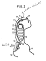
- the upper end portion 24 has a portion formed as a flap 28.
- the length of the flap 28 is slightly longer than the pack length L of the airbag 12.
- the airbag 12 In the folded state, the airbag 12 has a small thickness, but an elongated shape, so that it can be easily accommodated under the upper end part 24.
- the gas guide tube 22 also has a smaller cross section than the gas generator 20 and helps that the protective device can be easily accommodated in the panel of the door. Incidentally, the gas guide tube 22 extends over the entire pack length L of the gas bag. This has the advantage that the gas flows evenly over a large area in the gas bag and this can develop quickly and evenly, as will be explained below, down.
- gas bag including gas guide tube in cross section have small dimensions and can be easily accommodated under the upper end part 24.
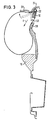
- the gas guide tube 22 and the gas bag 12 are surrounded by a receiving part 32, which forms, so to speak, a housing for the gas bag and the gas guide tube and can also be referred to as a gas bag module housing.
- the receiving part 32 holds the gas bag 12 in its folded state and is attached to the door panel via screws 34. More precisely, the receiving part 32 is screwed on the one hand to the so-called foam carrier part 36 of the upper end part 24. Adjoining the foam carrier part 36 is a foamed region 38 and to this an outside film 40 to form the upper closure part 24.
- the receiving part 32 is screwed on the other hand to another trim part.
- the upper end portion has a lower thin edge 42 which extends behind the trim strip 26 and is clamped by this.
- the trim strip 26 thereby forms a releasable attachment for the lower edge 42.
- the door inner panel bears the reference numeral 44th
- the gas generated by the gas generator 20 flows through the gas guide tube 22 into the interior of the airbag 12.
- the gas bag begins to unfold, the deployment must be made mainly only downwards.
- the gas bag 12 pushes the receiving part 32, which has an open profile in cross-section, and the lower edge 42 of the anchorage through the trim strip 26.
- the flap 28 pivots due to its flexibility to the outside and sets the pivoting action but a certain resistance.
- Between flap 28 and trim strip 26 results in a so-called shot channel 50, which dictates the direction of unfolding at the beginning of the deployment process.
- the main deployment direction, represented by the arrow R is thus obliquely downwards.
- the gas bag 12 is thereby not quickly deployed in the direction of the occupant, but down, preferably parallel to the door and as quickly as possible to provide its entire surface as a retaining surface.
- the illustrated protective device is integrated in the door trim 10 and forms with it a preassembled unit.
- the protective device according to the invention represents a low risk potential for occupants who lean on the side wall or door, since the flap 28 does not swing very far outward and the gas bag unfolds down. An inferior to the flap 28 occupant can not significantly delay the unfolding, since the flap 28 is very long, so there is a long opening line along which the airbag 12 can deploy.
Landscapes
- Engineering & Computer Science (AREA)
- Mechanical Engineering (AREA)
- Air Bags (AREA)
- Vehicle Interior And Exterior Ornaments, Soundproofing, And Insulation (AREA)
Claims (14)
- Dispositif de protection gonflable contre les impacts latéraux pour des occupants d'un véhicule, lequel est intégré dans une paroi latérale du véhicule, comportant
un coussin à gaz (12),
un générateur de gaz (20) et
une garniture de paroi latérale (10),
la garniture de paroi latérale (10) présentant une partie de terminaison supérieure (24) qui termine la garniture vers le bord inférieur (14) du tronçon de fenêtre (13),
la partie de terminaison supérieure (24) étant réalisée au moins par tronçons sous la forme d'un volet (28) qui, lorsqu'il est ouvert par pivotement, définit un canal d'éjection (50) dirigé vers le bas pour le coussin à gaz (12),
caractérisé en ce que le coussin à gaz (12) est fixé à son extrémité supérieure et est agencé plié au-dessous de la partie de terminaison supérieure (24),
et le coussin à gaz (12) à l'état déployé recouvre sur une grande surface la garniture de paroi latérale (10) latéralement à la région du thorax et du bassin de l'occupant par une partie gonflée s'étendant depuis le bord inférieur (14) du tronçon de fenêtre (13) de manière continue jusque sur le côté de la région du bassin. - Dispositif de protection selon la revendication 1, caractérisé en ce que la partie de terminaison (24) présente un bord inférieur (42) qui est maintenu en place sur le reste de la garniture de paroi latérale (10) au moyen d'une fixation qui peut être détachée par le coussin à gaz (12) qui se déploie.
- Dispositif de protection selon la revendication 2, caractérisé en ce que la fixation détachable est une moulure décorative (26) de la garniture de paroi latérale (10), derrière laquelle s'étend le bord inférieur (42) et qui serre le bord inférieur (42).
- Dispositif de protection selon l'une des revendications précédentes, caractérisé en ce que le coussin à gaz (12) s'étend à l'état déployé au moins jusqu'à l'accoudoir (16) dans la paroi latérale.
- Dispositif de protection selon l'une des revendications précédentes, caractérisé en ce que le coussin à gaz (12) à l'état plié a une forme allongée.
- Dispositif de protection selon l'une des revendications précédentes, caractérisé en ce que le générateur de gaz (20) est agencé en dehors du coussin à gaz (12).
- Dispositif de protection selon la revendication 6, caractérisé en ce que le générateur de gaz (20) est relié avec l'intérieur du coussin à gaz (12) au moyen d'un tube de conduite de gaz (22) s'étendant sur la longueur de paquet (L) du coussin à gaz (12) et jusque dans celui-ci.
- Dispositif de protection selon la revendication 7, caractérisé par une partie de logement (32) flexible pour le coussin à gaz (12) plié et pour le tube de conduite de gaz (22), la partie de logement (32) étant fixée sur la garniture de paroi latérale (10).
- Dispositif de protection selon la revendication 8, caractérisé en ce qu'il est intégré dans la garniture de paroi latérale (10) et qu'il forme avec celle-ci une unité préassemblée.
- Dispositif de protection selon l'une des revendications précédentes, caractérisé en ce que le coussin à gaz (12) qui se déploie s'étend sur au moins approximativement la moitié de la longueur de la paroi latérale associée.
- Dispositif de protection selon l'une des revendications précédentes, caractérisé en ce que le coussin à gaz (12) est relié en écoulement à un deuxième coussin à gaz par l'intermédiaire d'une conduite.
- Dispositif de protection selon l'une des revendications précédentes, caractérisé en ce que la garniture de paroi latérale (10) est une garniture de portière.
- Dispositif de protection selon l'une des revendications précédentes, caractérisé en ce qu'il est intégré dans la portière avant et le coussin à gaz (12) déployé s'étend au-delà de la portière vers l'arrière et recouvre la colonne B (18) du véhicule en direction longitudinale.
- Dispositif de protection selon l'une des revendications précédentes, caractérisé en ce que le volet (28) présente une longueur qui correspond au moins à la longueur de paquet (L) du coussin à gaz (12).
Applications Claiming Priority (2)
| Application Number | Priority Date | Filing Date | Title |
|---|---|---|---|
| DE29915820U DE29915820U1 (de) | 1999-09-08 | 1999-09-08 | Seitenaufprall-Schutzeinrichtung |
| DE29915820U | 1999-09-08 |
Publications (3)
| Publication Number | Publication Date |
|---|---|
| EP1083100A2 EP1083100A2 (fr) | 2001-03-14 |
| EP1083100A3 EP1083100A3 (fr) | 2003-08-20 |
| EP1083100B1 true EP1083100B1 (fr) | 2006-05-17 |
Family
ID=8078649
Family Applications (1)
| Application Number | Title | Priority Date | Filing Date |
|---|---|---|---|
| EP00118281A Expired - Lifetime EP1083100B1 (fr) | 1999-09-08 | 2000-09-05 | Système de protection en cas de choc latéral |
Country Status (5)
| Country | Link |
|---|---|
| US (1) | US6325410B1 (fr) |
| EP (1) | EP1083100B1 (fr) |
| JP (1) | JP2001088652A (fr) |
| DE (2) | DE29915820U1 (fr) |
| ES (1) | ES2263418T3 (fr) |
Families Citing this family (22)
| Publication number | Priority date | Publication date | Assignee | Title |
|---|---|---|---|---|
| US6502856B1 (en) * | 2000-02-11 | 2003-01-07 | International Truck Intellectual Property Company, L.L.C. | Rollover air bag system |
| WO2001083271A1 (fr) * | 2000-05-01 | 2001-11-08 | Toyoda Gosei Co., Ltd. | Dispositif de retenue de passager |
| FR2808744B1 (fr) * | 2000-05-09 | 2002-08-23 | Ecia Equip Composants Ind Auto | Panneau de revetement d'une porte laterale de vehicule equipe d'un couvercle articulable, et porte de vehicule equipee de ce panneau |
| US7828321B2 (en) * | 2000-09-28 | 2010-11-09 | Trw Vehicle Safety Systems, Inc. | Inflatable side curtain that moves occupant's head away from vehicle side structure |
| US6508486B1 (en) * | 2001-06-06 | 2003-01-21 | Delphi Technologies, Inc. | Door mounted side restraint |
| DE10220051B4 (de) * | 2002-05-04 | 2016-12-15 | Volkswagen Ag | Sicherheitsvorrichtung an einer Türbrüstung einer Fahrzeugtür |
| JP3724796B2 (ja) * | 2002-09-09 | 2005-12-07 | 本田技研工業株式会社 | 乗員保護装置 |
| DE102004013036B4 (de) † | 2004-03-26 | 2011-04-14 | Faurecia Innenraum Systeme Gmbh | Vorrichtung zum Kopf- und/oder Schulteraufprallschutz bei einer Seitenkollision und/oder einem Überschlag |
| US7871119B2 (en) * | 2004-04-30 | 2011-01-18 | International Automotive Components Group North America, Inc. | Door trim panel with dual density bolster armrest and integrated components |
| US7104590B2 (en) * | 2004-07-01 | 2006-09-12 | Lear Corporation | Vehicle trim panel with integral nibbed armrest |
| US7108312B2 (en) | 2004-11-09 | 2006-09-19 | Lear Corporation | Vehicle door trim bolster with multi-feel cover and method of making the same |
| DE102005006770B3 (de) * | 2005-02-15 | 2006-05-18 | Lisa Dräxlmaier GmbH | Bauteil, insbesondere Innenverkleidungsteil für Innenräume von Kraftfahrzeugen |
| US8221843B2 (en) * | 2005-02-15 | 2012-07-17 | Lisa Dräxlmaier GmbH | Methods and compositions for coating interior components of motor vehicles and interior components of motor vehicles coated using same |
| DE102005010024B4 (de) * | 2005-03-04 | 2015-06-11 | Lisa Dräxlmaier GmbH | Fahrzeugtürverkleidung und Verfahren zu deren Herstellung |
| DE102005010025B4 (de) * | 2005-03-04 | 2008-01-24 | Lisa Dräxlmaier GmbH | Fahrzeugtürverkleidung und Verfahren zu deren Herstellung |
| DE102005013477B4 (de) * | 2005-03-23 | 2008-12-04 | Lisa Dräxlmaier GmbH | Kraftfahrzeugverkleidungsteil mit Schwächungsstellen und Verfahren zu dessen Herstellung |
| DE102005034354B4 (de) * | 2005-07-22 | 2014-08-28 | Lisa Dräxlmaier GmbH | Airbagabdeckung |
| US7578518B2 (en) * | 2005-11-17 | 2009-08-25 | Honda Motor Co., Ltd. | Occupant protection device |
| US20070241542A1 (en) * | 2006-04-18 | 2007-10-18 | Mark Wallace | Air Bag Deployment Ramp |
| JP4861282B2 (ja) * | 2007-09-27 | 2012-01-25 | 本田技研工業株式会社 | エアバッグのカバー体及びエアバッグ装置 |
| JP5324810B2 (ja) * | 2008-04-11 | 2013-10-23 | 河西工業株式会社 | 車両用内装部品 |
| CN102529866B (zh) * | 2012-01-13 | 2014-07-16 | 浙江吉利汽车研究院有限公司 | 汽车侧面保护装置 |
Family Cites Families (15)
| Publication number | Priority date | Publication date | Assignee | Title |
|---|---|---|---|---|
| DE433069C (de) | 1926-08-23 | Siegfried Saul | Verfahren zur Erzeugung von Bildern, Figuren und Dessins auf Gummiflaechen | |
| JP2921996B2 (ja) | 1991-01-31 | 1999-07-19 | マツダ株式会社 | 車体側部のエネルギ吸収構造 |
| US5324072A (en) * | 1992-09-23 | 1994-06-28 | Morton International, Inc. | Side impact air bag |
| US5308112A (en) * | 1993-04-21 | 1994-05-03 | General Motors Corporation | Unfurled side impact air bag |
| DE4330692C2 (de) | 1993-09-10 | 2002-06-20 | Siemens Restraint Systems Gmbh | Abdeckung der Austrittsöffnung für den Gassack einer hinter der Innenverkleidung eines Kraftfahrzeugs eingebauten Gassack-Aufprall-Schutzeinheit |
| US5556128A (en) * | 1994-11-24 | 1996-09-17 | Volkswagen Ag | Safety arrangement for a vehicle occupant |
| DE29517373U1 (de) * | 1995-11-02 | 1996-03-07 | Trw Repa Gmbh | Gassack-Seitenaufprall-Schutzeinrichtung für Fahrzeuginsassen |
| DE29603316U1 (de) | 1996-02-23 | 1996-06-20 | Trw Occupant Restraint Systems Gmbh, 73551 Alfdorf | Seitenaufprall-Schutzeinrichtung für Fahrzeuginsassen |
| DE29604892U1 (de) | 1996-03-16 | 1996-09-19 | Deter, Thomas, 12163 Berlin | Seitenairbag mit integriertem Prallpolster und Abstützung im Kopfbereich |
| DE59712913D1 (de) * | 1996-06-14 | 2008-03-20 | Volkswagen Ag | Airbageinrichtung |
| DE19632616B4 (de) * | 1996-08-13 | 2004-10-07 | Saint-Gobain Sekurit Deutschland Gmbh & Co. Kg | Seitenaufprallschutz für Fahrzeuginsassen |
| DE19641670A1 (de) * | 1996-10-10 | 1998-04-23 | Pars Passive Rueckhaltesysteme | Passives Rückhaltesystem für ein Kraftfahrzeug |
| DE19720587A1 (de) * | 1997-05-16 | 1998-11-19 | Porsche Ag | Seitenaufprallschutzeinrichtung für einen Insassen eines Fahrzeuges |
| DE19720585A1 (de) * | 1997-05-16 | 1998-11-19 | Porsche Ag | Seitenaufprallschutzeinrichtung für einen Insassen eines Fahrzeuges |
| DE19720588A1 (de) * | 1997-05-16 | 1998-11-19 | Porsche Ag | Aufprallschutzeinrichtung für einen Insassen eins Fahrzeuges |
-
1999
- 1999-09-08 DE DE29915820U patent/DE29915820U1/de not_active Expired - Lifetime
-
2000
- 2000-09-05 ES ES00118281T patent/ES2263418T3/es not_active Expired - Lifetime
- 2000-09-05 EP EP00118281A patent/EP1083100B1/fr not_active Expired - Lifetime
- 2000-09-05 DE DE50012755T patent/DE50012755D1/de not_active Expired - Fee Related
- 2000-09-07 JP JP2000271042A patent/JP2001088652A/ja active Pending
- 2000-09-08 US US09/659,427 patent/US6325410B1/en not_active Expired - Fee Related
Also Published As
| Publication number | Publication date |
|---|---|
| DE29915820U1 (de) | 2000-01-13 |
| US6325410B1 (en) | 2001-12-04 |
| DE50012755D1 (de) | 2006-06-22 |
| JP2001088652A (ja) | 2001-04-03 |
| EP1083100A3 (fr) | 2003-08-20 |
| ES2263418T3 (es) | 2006-12-16 |
| EP1083100A2 (fr) | 2001-03-14 |
Similar Documents
| Publication | Publication Date | Title |
|---|---|---|
| EP0798168B1 (fr) | Dispositif de protection contre le choc latéral pour les occupants d'un véhicule | |
| DE69903797T2 (de) | Nahtlose airbag-abdeckung für ein armaturenbrett | |
| DE69828681T2 (de) | Airbag vorrichtung für seitenaufprall bei fahrzeugen | |
| DE19815381C5 (de) | Dachhimmelverkleidung | |
| EP1083100A2 (fr) | Système de protection en cas de choc latéral | |
| DE19632222B4 (de) | Innenverkleidung für ein Fahrzeugdach | |
| DE69912401T2 (de) | Seitenairbag vorrichtung | |
| EP0791511B2 (fr) | Dispositif de protection des passagers d'un véhicule contre les chocs latéraux | |
| DE60016470T2 (de) | Seiten airbag-vorhang- modul | |
| DE102007059882B4 (de) | Heckaufprall-Airbagsystem | |
| DE19860312B4 (de) | Fahrzeugsitz mit einem seitlichen aufblasbaren Sicherheitssack | |
| EP0771699A2 (fr) | Dispositif de protection contre les chocs latéraux à coussin gonflable, pour occupants de véhicules | |
| DE19860827A1 (de) | Rückhaltesystem für einen Frontalaufprall eines Fahrzeugs | |
| EP1403150B1 (fr) | Dispositif de protection du passager | |
| DE10063473B4 (de) | Dachholm-Verkleidung für aufblasbares Rückhaltesystem | |
| DE10012430A1 (de) | Fahrzeuginsassenschutzvorrichtung einschließlich eines aufblasbaren Vorhangs und eines den Vorhang enthaltenden Gehäuses | |
| EP1698525A1 (fr) | Panneau de revêtement d'une porte de véhicule et la méthode de production | |
| EP1445156B1 (fr) | Dispositif de protection contre le choc latéral pour un occupant de véhicule | |
| DE19750945A1 (de) | Seitenaufprallschutzmodul zur Montage an einem Sitz eines Kraftfahrzeugs | |
| DE19925441A1 (de) | Fahrzeuginsassenrückhaltevorrichtung | |
| DE10140363B4 (de) | An der Tür angebrachte rohrförmige Struktur | |
| DE19745872A1 (de) | Airbageinrichtung | |
| EP1426244B1 (fr) | Véhicule avec structure de carrosserie et un dispostif de protection en cas de choc latéral | |
| DE102007003863A1 (de) | Seitengassackanordnung | |
| DE102004014742B4 (de) | Fahrzeug mit Vorhang-Airbag |
Legal Events
| Date | Code | Title | Description |
|---|---|---|---|
| PUAI | Public reference made under article 153(3) epc to a published international application that has entered the european phase |
Free format text: ORIGINAL CODE: 0009012 |
|
| AK | Designated contracting states |
Kind code of ref document: A2 Designated state(s): AT BE CH CY DE DK ES FI FR GB GR IE IT LI LU MC NL PT SE |
|
| AX | Request for extension of the european patent |
Free format text: AL;LT;LV;MK;RO;SI |
|
| PUAL | Search report despatched |
Free format text: ORIGINAL CODE: 0009013 |
|
| AK | Designated contracting states |
Designated state(s): AT BE CH CY DE DK ES FI FR GB GR IE IT LI LU MC NL PT SE |
|
| AX | Request for extension of the european patent |
Extension state: AL LT LV MK RO SI |
|
| RIC1 | Information provided on ipc code assigned before grant |
Ipc: 7B 60R 21/22 A Ipc: 7B 60R 21/16 B Ipc: 7B 60R 21/20 B |
|
| 17P | Request for examination filed |
Effective date: 20040105 |
|
| AKX | Designation fees paid |
Designated state(s): DE ES FR GB IT |
|
| 17Q | First examination report despatched |
Effective date: 20040504 |
|
| GRAP | Despatch of communication of intention to grant a patent |
Free format text: ORIGINAL CODE: EPIDOSNIGR1 |
|
| GRAS | Grant fee paid |
Free format text: ORIGINAL CODE: EPIDOSNIGR3 |
|
| GRAA | (expected) grant |
Free format text: ORIGINAL CODE: 0009210 |
|
| RAP1 | Party data changed (applicant data changed or rights of an application transferred) |
Owner name: TRW AUTOMOTIVE GMBH |
|
| AK | Designated contracting states |
Kind code of ref document: B1 Designated state(s): DE ES FR GB IT |
|
| REG | Reference to a national code |
Ref country code: GB Ref legal event code: FG4D Free format text: NOT ENGLISH |
|
| RIC1 | Information provided on ipc code assigned before grant |
Ipc: B60R 21/16 20060101ALI20060324BHEP Ipc: B60R 21/20 20060101AFI20060324BHEP |
|
| REF | Corresponds to: |
Ref document number: 50012755 Country of ref document: DE Date of ref document: 20060622 Kind code of ref document: P |
|
| PGFP | Annual fee paid to national office [announced via postgrant information from national office to epo] |
Ref country code: GB Payment date: 20060804 Year of fee payment: 7 |
|
| GBT | Gb: translation of ep patent filed (gb section 77(6)(a)/1977) |
Effective date: 20060719 |
|
| PGFP | Annual fee paid to national office [announced via postgrant information from national office to epo] |
Ref country code: FR Payment date: 20060906 Year of fee payment: 7 |
|
| PGFP | Annual fee paid to national office [announced via postgrant information from national office to epo] |
Ref country code: ES Payment date: 20060920 Year of fee payment: 7 |
|
| PGFP | Annual fee paid to national office [announced via postgrant information from national office to epo] |
Ref country code: DE Payment date: 20060929 Year of fee payment: 7 |
|
| PGFP | Annual fee paid to national office [announced via postgrant information from national office to epo] |
Ref country code: IT Payment date: 20060930 Year of fee payment: 7 |
|
| ET | Fr: translation filed | ||
| REG | Reference to a national code |
Ref country code: ES Ref legal event code: FG2A Ref document number: 2263418 Country of ref document: ES Kind code of ref document: T3 |
|
| PLBE | No opposition filed within time limit |
Free format text: ORIGINAL CODE: 0009261 |
|
| STAA | Information on the status of an ep patent application or granted ep patent |
Free format text: STATUS: NO OPPOSITION FILED WITHIN TIME LIMIT |
|
| 26N | No opposition filed |
Effective date: 20070220 |
|
| GBPC | Gb: european patent ceased through non-payment of renewal fee |
Effective date: 20070905 |
|
| PG25 | Lapsed in a contracting state [announced via postgrant information from national office to epo] |
Ref country code: DE Free format text: LAPSE BECAUSE OF NON-PAYMENT OF DUE FEES Effective date: 20080401 |
|
| REG | Reference to a national code |
Ref country code: FR Ref legal event code: ST Effective date: 20080531 |
|
| PG25 | Lapsed in a contracting state [announced via postgrant information from national office to epo] |
Ref country code: FR Free format text: LAPSE BECAUSE OF NON-PAYMENT OF DUE FEES Effective date: 20071001 |
|
| PG25 | Lapsed in a contracting state [announced via postgrant information from national office to epo] |
Ref country code: GB Free format text: LAPSE BECAUSE OF NON-PAYMENT OF DUE FEES Effective date: 20070905 |
|
| REG | Reference to a national code |
Ref country code: ES Ref legal event code: FD2A Effective date: 20070906 |
|
| PG25 | Lapsed in a contracting state [announced via postgrant information from national office to epo] |
Ref country code: ES Free format text: LAPSE BECAUSE OF NON-PAYMENT OF DUE FEES Effective date: 20070906 |
|
| PG25 | Lapsed in a contracting state [announced via postgrant information from national office to epo] |
Ref country code: IT Free format text: LAPSE BECAUSE OF NON-PAYMENT OF DUE FEES Effective date: 20070905 |