EP1083112A2 - Direction assistée électrique - Google Patents
Direction assistée électrique Download PDFInfo
- Publication number
- EP1083112A2 EP1083112A2 EP00119221A EP00119221A EP1083112A2 EP 1083112 A2 EP1083112 A2 EP 1083112A2 EP 00119221 A EP00119221 A EP 00119221A EP 00119221 A EP00119221 A EP 00119221A EP 1083112 A2 EP1083112 A2 EP 1083112A2
- Authority
- EP
- European Patent Office
- Prior art keywords
- worm
- tooth portion
- annular tooth
- teeth
- fibers
- Prior art date
- Legal status (The legal status is an assumption and is not a legal conclusion. Google has not performed a legal analysis and makes no representation as to the accuracy of the status listed.)
- Granted
Links
- 239000000835 fiber Substances 0.000 claims abstract description 33
- 229920003002 synthetic resin Polymers 0.000 claims abstract description 19
- 239000000057 synthetic resin Substances 0.000 claims abstract description 19
- 239000000463 material Substances 0.000 claims abstract description 15
- 239000002184 metal Substances 0.000 claims abstract description 8
- 239000003365 glass fiber Substances 0.000 claims description 6
- 238000001746 injection moulding Methods 0.000 claims description 5
- 229920000049 Carbon (fiber) Polymers 0.000 claims description 3
- 229920003233 aromatic nylon Polymers 0.000 claims description 3
- 239000004917 carbon fiber Substances 0.000 claims description 3
- VNWKTOKETHGBQD-UHFFFAOYSA-N methane Chemical compound C VNWKTOKETHGBQD-UHFFFAOYSA-N 0.000 claims description 3
- 238000002347 injection Methods 0.000 description 5
- 239000007924 injection Substances 0.000 description 5
- 239000004677 Nylon Substances 0.000 description 4
- 229920001778 nylon Polymers 0.000 description 4
- 230000004323 axial length Effects 0.000 description 2
- 229920002994 synthetic fiber Polymers 0.000 description 2
- 230000007423 decrease Effects 0.000 description 1
- 230000003247 decreasing effect Effects 0.000 description 1
- 238000006073 displacement reaction Methods 0.000 description 1
- 238000004519 manufacturing process Methods 0.000 description 1
- 230000000149 penetrating effect Effects 0.000 description 1
- 230000002093 peripheral effect Effects 0.000 description 1
- 230000003014 reinforcing effect Effects 0.000 description 1
- 229920005989 resin Polymers 0.000 description 1
- 239000011347 resin Substances 0.000 description 1
Images


Classifications
-
- B—PERFORMING OPERATIONS; TRANSPORTING
- B62—LAND VEHICLES FOR TRAVELLING OTHERWISE THAN ON RAILS
- B62D—MOTOR VEHICLES; TRAILERS
- B62D5/00—Power-assisted or power-driven steering
- B62D5/04—Power-assisted or power-driven steering electrical, e.g. using an electric servo-motor connected to, or forming part of, the steering gear
- B62D5/0409—Electric motor acting on the steering column
-
- F—MECHANICAL ENGINEERING; LIGHTING; HEATING; WEAPONS; BLASTING
- F16—ENGINEERING ELEMENTS AND UNITS; GENERAL MEASURES FOR PRODUCING AND MAINTAINING EFFECTIVE FUNCTIONING OF MACHINES OR INSTALLATIONS; THERMAL INSULATION IN GENERAL
- F16H—GEARING
- F16H55/00—Elements with teeth or friction surfaces for conveying motion; Worms, pulleys or sheaves for gearing mechanisms
- F16H55/02—Toothed members; Worms
- F16H55/06—Use of materials; Use of treatments of toothed members or worms to affect their intrinsic material properties
-
- Y—GENERAL TAGGING OF NEW TECHNOLOGICAL DEVELOPMENTS; GENERAL TAGGING OF CROSS-SECTIONAL TECHNOLOGIES SPANNING OVER SEVERAL SECTIONS OF THE IPC; TECHNICAL SUBJECTS COVERED BY FORMER USPC CROSS-REFERENCE ART COLLECTIONS [XRACs] AND DIGESTS
- Y10—TECHNICAL SUBJECTS COVERED BY FORMER USPC
- Y10S—TECHNICAL SUBJECTS COVERED BY FORMER USPC CROSS-REFERENCE ART COLLECTIONS [XRACs] AND DIGESTS
- Y10S74/00—Machine element or mechanism
- Y10S74/10—Polymer digest - plastic gears
-
- Y—GENERAL TAGGING OF NEW TECHNOLOGICAL DEVELOPMENTS; GENERAL TAGGING OF CROSS-SECTIONAL TECHNOLOGIES SPANNING OVER SEVERAL SECTIONS OF THE IPC; TECHNICAL SUBJECTS COVERED BY FORMER USPC CROSS-REFERENCE ART COLLECTIONS [XRACs] AND DIGESTS
- Y10—TECHNICAL SUBJECTS COVERED BY FORMER USPC
- Y10T—TECHNICAL SUBJECTS COVERED BY FORMER US CLASSIFICATION
- Y10T74/00—Machine element or mechanism
- Y10T74/19—Gearing
- Y10T74/19642—Directly cooperating gears
- Y10T74/19698—Spiral
- Y10T74/19828—Worm
Definitions
- the present invention relates to an electric power steering apparatus using a motor as a power source for steering assists.
- FIG. 1 shows a schematic cross sectional view of a conventional electric power steering apparatus.
- the electric power steering apparatus comprises a first steering shaft 2 connected with a steering wheel 1, a second steering shaft 4 connected with the first steering shaft 2 through a torsion bar 3, a torque sensor 5 for detecting the relative rotational displacement between the first and second steering shafts 2, 4, a motor 6 for steering assists, which is driven corresponding to the detected result of the torque sensor 5, and a reduction mechanism 9 having a worm 7 and a worm wheel 8 for reducing and transmitting the output power of the motor 6 to the second steering shaft 4.
- the operation of the steering mechanism corresponding to the turning of the steering wheel 1 is assisted by the rotation of the motor 6 so as to reduce the driver's burden at the steering.
- a worm shaft 10 is connected with the output shaft of the motor 6 and disposed to cross the shaft axis of the second steering shaft 4.
- the worm 7 is integrally formed with the worm shaft 10 at the middle portion thereof.
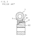
- FIG. 2 shows an enlarged cross sectional view of a worm wheel in an electric power steering apparatus disclosed in the Japanese Utility Model Publication No. 2556890.
- the worm wheel 8 comprises an annular tooth portion 81 and a boss portion 82.
- the annular tooth portion 81 is made of synthetic resin, and has teeth 8a engaging with the worm 7.
- the boss portion 82 is made of metal, and is engaging with the annular tooth portion 81 at the inside thereof. This structure allows not only to reduce the noise at the engaging of the worm wheel 8 and the worm 7, but also to excel in processability of the teeth.
- the annular tooth portion 81 is made of nylon synthetic resin material mixed with glass fibers.
- the glass fibers mixed in the nylon synthetic material, used in making the annular tooth portion of the conventional worm wheel has an aspect ratio (ratio of the length to the diameter) of less than 100. Due to the small aspect ratio, the fatigue strength of the teeth projecting from the peripheral of the annular tooth portion and that of the root portion of the teeth was not sufficient. Thus, the improvement of the fatigue strength of the teeth and the root portion of the teeth were desired. More precisely speaking, the annular tooth portion is formed by injection molding, in which nylon synthetic material is injected into a mould by an injection screw. And at the injection, the glass fibers mixed into the synthetic resin material run along the stream of the synthetic resin material into the mould. As a result, the directions of the fibers in the annular tooth portion become same.
- the aspect ratio of the fibers is smaller than 100, namely, the fibers are very short. Therefore, the fatigue strength of the teeth and that of the root portion of the teeth, where a strong torque is applied when the worm and worm wheel engages, was not sufficient.
- An object of the present invention is to provide an electric steering apparatus improved to solve the aforementioned problems.
- the electric steering apparatus comprises a motor for steering assists, a worm, a worm wheel having an annular tooth portion made of synthetic resin with teeth engaging with the worm and having a metal boss portion fitted in the inside of the annular tooth portion, and a steering shaft to which an output from the motor is transmitted through the worm and the worm wheel thereby to assist steering, characterized in that the annular tooth portion is made of the synthetic resin material mixed with fibers having a length with an aspect ratio between 100 and 800.
- the annular tooth portion is made of synthetic resin material mixed with fibers having an aspect ratio between 100 and 800, therefore, even when the longitudinal direction of the fibers is substantially parallel to the direction of the stream of the synthetic resin material in the mould, the fibers can be arranged preferably in the direction crossing the direction of the torque, which is applied to the teeth. As a result, the fatigue strength of the teeth and the root portion of the teeth can be reinforced.
- the aspect ratio of the fibers is less than 100, it is impossible to preferably arrange the fibers in the direction crossing the direction of the torque, which is applied to the teeth. As a result, only small reinforcing effect of the teeth and the root portion of the teeth can be attained by the fibers, and the fatigue strength of the teeth and the root portion of the teeth is insufficient.
- the fibers are cut by the injection screw, so that the aspect ratio decreases to less than 800, namely the length of the fibers with an aspect ratio over 800 cannot be realized.
- FIG.3 is a partial cross sectional view of the electric steering apparatus according to the present invention, showing the structure of the portions of the reduction mechanism and the motor.
- FIG. 4 is a detailed cross sectional view of the worm wheel of the electric steering apparatus according to the present invention.
- the reduction mechanism 9 comprises a worm 7 and a worm wheel 8, which engages with the worm 7.
- the worm 7 is integrally formed with the worm shaft 10 at the middle portion thereof.
- the worm shaft 10 is connected with an output shaft 6a of a motor 6 for steering assists and configured to cross the shaft axis of a second steering shaft 4.
- the worm wheel 8 is fitted and fixed to the middle portion of the second steering shaft 4.
- the worm wheel 8 comprises an annular tooth portion 81 made of a synthetic resin material having a plurality of teeth 8a engaging with the worm 7, and a metal boss portion 82.
- the metal boss portion 82 fits in the inner surface of the annular tooth portion 81 by the injection molding. It a through a hole 82a penetrating at the center portion of the boss portion 82 the second steering shaft 4 is fitted.
- FIGS. 5A, 5B are detailed cross sectional views of the worm wheel.
- the annular tooth portion 81 is made of synthetic resin material, such as nylon resin, mixed with fibers 81a having a length of an aspect ratio between 100 and 800.
- the fiber 81a is a glass fiber having a diameter of about 13 micrometers, a carbon fiber having a diameter of about 10 micrometers, or an aromatic nylon fiber having a diameter between about 10 and about 20 micrometers.
- the aspect ratio corresponding to the length of the fibers mixed into the synthetic resin material is between 100 and 800, the fatigue strength of the teeth and the root portion of the teeth can be increased, compared to a case that the aspect ratio is less than 100.
- the fibers can be preferably arranged in the direction crossing the direction of the torque, which is applied to the teeth 8a.
- the fibers 81a are bent, as shown in FIG. 5B, at the injection by the injection screw and by the transportation resistance in the mould. Therefore, the fibers can be preferably arranged in the direction crossing the direction of the torque, which is applied to the teeth 8a.
- the fatigue strength of the teeth and that of the root portion of the teeth increases, when the aspect ratio of the fibers mixed into the synthetic resin material is between 100 and 800. Therefore, the thickness of the annular tooth portion 81, namely the distance between the root portion of the teeth and the inner surface of the annular tooth portion, can be reduced compared to a case that the aspect ratio corresponding to the length of fibers is less than 100.
- the consumption of the synthetic resin material which is more expensive than metal, can be reduced.
- the time required for an injection molding for each product can be shortened so that the fabrication cost can be decreased.
- FIG. 6 is a detailed cross sectional view of the worm wheel 8.
- a pair of annular recesses 83, 83 are formed at both ends of the boss portion 82 in the axial direction, and a pair of annular projecting portions 84, 84 are integrally formed at both ends of the annular tooth portion 81 in the axial direction.
- the boss portion 82 and the annular tooth portion 81 are engaging with each other through these annular recesses 83, 83 and the annular projecting portions 84, 84.
- the radial lengths (a) of the recesses 83, 83 and that of the projecting portions 84, 84 are designed to be 1 to 1.5 times of the axial lengths (b) of the recesses 83, 83 and that of the projecting portions 84, 84.
- the axial lengths (c) of the annular tooth portion 81 and that of the boss portion 82 are designed to be 2.5 to 6 times of the above-defined length (b).
Landscapes
- Engineering & Computer Science (AREA)
- Mechanical Engineering (AREA)
- General Engineering & Computer Science (AREA)
- Chemical & Material Sciences (AREA)
- Combustion & Propulsion (AREA)
- Transportation (AREA)
- Physics & Mathematics (AREA)
- Electromagnetism (AREA)
- Thermal Sciences (AREA)
- Gears, Cams (AREA)
- Power Steering Mechanism (AREA)
Applications Claiming Priority (2)
| Application Number | Priority Date | Filing Date | Title |
|---|---|---|---|
| JP25489199A JP3765208B2 (ja) | 1999-09-08 | 1999-09-08 | 電動式舵取装置 |
| JP25489199 | 1999-09-08 |
Publications (3)
| Publication Number | Publication Date |
|---|---|
| EP1083112A2 true EP1083112A2 (fr) | 2001-03-14 |
| EP1083112A3 EP1083112A3 (fr) | 2005-08-03 |
| EP1083112B1 EP1083112B1 (fr) | 2007-05-23 |
Family
ID=17271287
Family Applications (1)
| Application Number | Title | Priority Date | Filing Date |
|---|---|---|---|
| EP00119221A Expired - Lifetime EP1083112B1 (fr) | 1999-09-08 | 2000-09-06 | Direction assistée électrique |
Country Status (4)
| Country | Link |
|---|---|
| US (1) | US6626261B1 (fr) |
| EP (1) | EP1083112B1 (fr) |
| JP (1) | JP3765208B2 (fr) |
| DE (1) | DE60034912T2 (fr) |
Cited By (4)
| Publication number | Priority date | Publication date | Assignee | Title |
|---|---|---|---|---|
| EP1780444A4 (fr) * | 2004-07-29 | 2011-03-02 | Nsk Ltd | Engrenage de réduction de vitesse |
| WO2013068208A1 (fr) * | 2011-11-10 | 2013-05-16 | Rud Ketten Rieger & Dietz Gmbh U. Co. Kg | Pignon à poches moulé par injection constitué de matière plastique renforcée de fibres |
| CN103661569A (zh) * | 2013-12-19 | 2014-03-26 | 浙江百瑞传动科技有限公司 | 一种汽车电动助力转向器蜗轮 |
| DE102017122896A1 (de) | 2017-10-02 | 2019-04-04 | Thyssenkrupp Ag | Schneckenrad für ein Schneckenradgetriebe einer Kraftfahrzeuglenkung aus faserverstärktem Kunststoff mit gezielter Orientierung der Fasern |
Families Citing this family (12)
| Publication number | Priority date | Publication date | Assignee | Title |
|---|---|---|---|---|
| JP2002310267A (ja) * | 2001-04-10 | 2002-10-23 | Bando Chem Ind Ltd | 樹脂製ウォームホイール並びにその製造装置及び製造方法 |
| US6976556B2 (en) * | 2002-08-06 | 2005-12-20 | Honda Giken Kogyo Kabushiki Kaisha | Electric power steering apparatus |
| US7360468B2 (en) | 2003-03-19 | 2008-04-22 | Nsk Ltd. | Electric power steering device and resin gear used for the same |
| JP2005138670A (ja) * | 2003-11-05 | 2005-06-02 | Koyo Seiko Co Ltd | 電動パワーステアリング装置および電動モータの組立方法 |
| US7979988B2 (en) * | 2007-06-26 | 2011-07-19 | Hitachi, Ltd. | Worm gear unit and method of producing same |
| US8328464B2 (en) * | 2011-02-04 | 2012-12-11 | Wacker Neuson Production Americas Llc | Vibratory roller with composite exciter drive gear |
| JP2014009789A (ja) * | 2012-07-02 | 2014-01-20 | Jtekt Corp | 電動パワーステアリング装置 |
| JP6156695B2 (ja) * | 2012-09-20 | 2017-07-05 | 日立化成株式会社 | ギヤ装置 |
| JP6547855B2 (ja) * | 2016-02-02 | 2019-07-24 | 日本精工株式会社 | ウォーム減速機、及びウォーム減速機の製造方法 |
| US11248692B2 (en) * | 2016-03-11 | 2022-02-15 | Deere & Company | Composite gears and methods of manufacturing such gears |
| CN107769456A (zh) * | 2017-11-30 | 2018-03-06 | 深圳市昱森机电有限公司 | 自锁直流电机及升降桌 |
| US11267191B2 (en) * | 2019-05-07 | 2022-03-08 | GM Global Technology Operations LLC | Methods for composite part manufacturing |
Citations (1)
| Publication number | Priority date | Publication date | Assignee | Title |
|---|---|---|---|---|
| JP2556890B2 (ja) | 1988-10-11 | 1996-11-27 | 日産自動車株式会社 | ディーゼル機関の燃料噴射制御装置 |
Family Cites Families (15)
| Publication number | Priority date | Publication date | Assignee | Title |
|---|---|---|---|---|
| US1638012A (en) * | 1924-04-11 | 1927-08-09 | Gen Electric | Blank for gears and method of making the same |
| US1601911A (en) * | 1924-09-22 | 1926-10-05 | Gen Electric | Textile-material gear and blank and method of making the same |
| US3931094A (en) * | 1973-07-02 | 1976-01-06 | Allied Chemical Corporation | Filled thermoplastic containing fibrous dispersion aid |
| JPS5865365A (ja) * | 1981-10-14 | 1983-04-19 | Mitsubishi Rayon Co Ltd | 繊維強化複合材料製歯車 |
| GB8400291D0 (en) * | 1984-01-06 | 1984-02-08 | Wiggins Teape Group Ltd | Fibre reinforced plastics sheets |
| JPS60206628A (ja) * | 1984-03-30 | 1985-10-18 | Mitsubishi Rayon Co Ltd | 歯車の製造法 |
| JPH0426754Y2 (fr) * | 1987-10-23 | 1992-06-26 | ||
| US5074828A (en) * | 1990-04-13 | 1991-12-24 | The Gates Rubber Company | Composite power transmission wheel |
| DE4232316C1 (de) * | 1992-09-26 | 1994-03-24 | Deutsche Forsch Luft Raumfahrt | Verfahren zum Herstellen von Ringen für Zahnräder mit Innen- und Außenverzahnung sowie Verwendung eines solchen Integralringes zur Herstellung von innen- oder außenverzahnten Zahnrädern |
| DE69400570T2 (de) * | 1993-12-07 | 1997-03-27 | Koyo Seiko Co | Servolenkung |
| JP3379092B2 (ja) * | 1994-02-04 | 2003-02-17 | 日本精工株式会社 | 電動式パワーステアリング装置 |
| JP3604460B2 (ja) * | 1995-06-14 | 2004-12-22 | 光洋精工株式会社 | 電動パワーステアリング装置 |
| JPH0989081A (ja) * | 1995-09-28 | 1997-03-31 | Fuji Heavy Ind Ltd | 汎用エンジンの射出成形ギヤ及びその製造方法 |
| US5962376A (en) * | 1997-02-25 | 1999-10-05 | Ntn Corporation | Resin composition for sliding member and resin gear |
| DE19712287C1 (de) * | 1997-03-24 | 1998-08-20 | Deutsch Zentr Luft & Raumfahrt | Gezahntes Bauelement zur mechanischen Kraftübertragung |
-
1999
- 1999-09-08 JP JP25489199A patent/JP3765208B2/ja not_active Expired - Fee Related
-
2000
- 2000-09-06 EP EP00119221A patent/EP1083112B1/fr not_active Expired - Lifetime
- 2000-09-06 DE DE60034912T patent/DE60034912T2/de not_active Expired - Lifetime
- 2000-09-08 US US09/657,976 patent/US6626261B1/en not_active Expired - Lifetime
Patent Citations (1)
| Publication number | Priority date | Publication date | Assignee | Title |
|---|---|---|---|---|
| JP2556890B2 (ja) | 1988-10-11 | 1996-11-27 | 日産自動車株式会社 | ディーゼル機関の燃料噴射制御装置 |
Cited By (5)
| Publication number | Priority date | Publication date | Assignee | Title |
|---|---|---|---|---|
| EP1780444A4 (fr) * | 2004-07-29 | 2011-03-02 | Nsk Ltd | Engrenage de réduction de vitesse |
| WO2013068208A1 (fr) * | 2011-11-10 | 2013-05-16 | Rud Ketten Rieger & Dietz Gmbh U. Co. Kg | Pignon à poches moulé par injection constitué de matière plastique renforcée de fibres |
| US9512913B2 (en) | 2011-11-10 | 2016-12-06 | Rud Ketten Rieger & Dietz Gmbh U. Co. K.G. | Injection-molded pocket-type chain wheel made of fiber-reinforced plastic |
| CN103661569A (zh) * | 2013-12-19 | 2014-03-26 | 浙江百瑞传动科技有限公司 | 一种汽车电动助力转向器蜗轮 |
| DE102017122896A1 (de) | 2017-10-02 | 2019-04-04 | Thyssenkrupp Ag | Schneckenrad für ein Schneckenradgetriebe einer Kraftfahrzeuglenkung aus faserverstärktem Kunststoff mit gezielter Orientierung der Fasern |
Also Published As
| Publication number | Publication date |
|---|---|
| JP3765208B2 (ja) | 2006-04-12 |
| EP1083112A3 (fr) | 2005-08-03 |
| US6626261B1 (en) | 2003-09-30 |
| DE60034912T2 (de) | 2008-01-24 |
| DE60034912D1 (de) | 2007-07-05 |
| EP1083112B1 (fr) | 2007-05-23 |
| JP2001071921A (ja) | 2001-03-21 |
Similar Documents
| Publication | Publication Date | Title |
|---|---|---|
| EP1083112A2 (fr) | Direction assistée électrique | |
| US8096204B2 (en) | Gear and electric power steering device | |
| US6988582B2 (en) | Gear, reduction gear combination and electric power steering apparatus | |
| US6644431B2 (en) | Electric power steering apparatus and method of manufacturing gear used therefor | |
| EP1416180B1 (fr) | Mécanisme d'articulation pour un dispositif de direction assistée | |
| DE102016224638B4 (de) | Untersetzungsgetriebe für elektrische Servolenkvorrichtung | |
| US20020020578A1 (en) | Electric power steering device | |
| JP2009121499A (ja) | ウォームギヤおよび電動パワーステアリング装置 | |
| US6425455B1 (en) | Electric power steering apparatus | |
| KR100828865B1 (ko) | 웜 휠 및 전동 파워 스티어링 장치 | |
| US6557663B2 (en) | Electric power steering apparatus | |
| DE102017122896A1 (de) | Schneckenrad für ein Schneckenradgetriebe einer Kraftfahrzeuglenkung aus faserverstärktem Kunststoff mit gezielter Orientierung der Fasern | |
| US20240059346A1 (en) | Reducer of electric power steering device and method for manufacturing the same | |
| CN116438105B (zh) | 齿轮与旋转轴的组装体及其组装方法 | |
| US6516915B2 (en) | Electric power steering device | |
| JPS62251522A (ja) | 回転軸の連結方法 | |
| WO2019228965A1 (fr) | Dispositif de détection destiné à détecter la position de rotation d'un arbre rotatif comportant un aimant émetteur moulé par injection sur l'arbre | |
| JP2009041683A (ja) | 樹脂製ウォームホイール | |
| JP2017194127A (ja) | ウォーム減速機および電動パワーステアリング装置 | |
| JP2003184995A (ja) | 減速歯車機構及び電動式パワーステアリング装置 | |
| CN117588548A (zh) | 电动助力转向装置的减速器及其制造方法 | |
| JP7318440B2 (ja) | ウォームホイール及びその製造方法、ウォーム減速機 | |
| KR100764234B1 (ko) | 자동차 조향장치의 랙 바와 볼 하우징간의 조립부 구조 | |
| KR20060035865A (ko) | 칼럽타입 전동식 파워 스티어링 장치 | |
| KR940002897Y1 (ko) | 동력 스티어링장치 |
Legal Events
| Date | Code | Title | Description |
|---|---|---|---|
| PUAI | Public reference made under article 153(3) epc to a published international application that has entered the european phase |
Free format text: ORIGINAL CODE: 0009012 |
|
| AK | Designated contracting states |
Kind code of ref document: A2 Designated state(s): AT BE CH CY DE DK ES FI FR GB GR IE IT LI LU MC NL PT SE |
|
| AX | Request for extension of the european patent |
Free format text: AL;LT;LV;MK;RO;SI |
|
| PUAL | Search report despatched |
Free format text: ORIGINAL CODE: 0009013 |
|
| AK | Designated contracting states |
Kind code of ref document: A3 Designated state(s): AT BE CH CY DE DK ES FI FR GB GR IE IT LI LU MC NL PT SE |
|
| AX | Request for extension of the european patent |
Extension state: AL LT LV MK RO SI |
|
| 17P | Request for examination filed |
Effective date: 20050813 |
|
| AKX | Designation fees paid |
Designated state(s): DE FR GB |
|
| RAP1 | Party data changed (applicant data changed or rights of an application transferred) |
Owner name: JTEKT CORPORATION |
|
| GRAP | Despatch of communication of intention to grant a patent |
Free format text: ORIGINAL CODE: EPIDOSNIGR1 |
|
| RIN1 | Information on inventor provided before grant (corrected) |
Inventor name: KUROKAWA, TAKANORI,C/O KOYA SEIKO CO. LTD., Inventor name: ARAI, HIROKAZU,C/O KOYA SEIKO CO. LTD., |
|
| GRAS | Grant fee paid |
Free format text: ORIGINAL CODE: EPIDOSNIGR3 |
|
| GRAA | (expected) grant |
Free format text: ORIGINAL CODE: 0009210 |
|
| AK | Designated contracting states |
Kind code of ref document: B1 Designated state(s): DE FR GB |
|
| REG | Reference to a national code |
Ref country code: GB Ref legal event code: FG4D |
|
| REF | Corresponds to: |
Ref document number: 60034912 Country of ref document: DE Date of ref document: 20070705 Kind code of ref document: P |
|
| ET | Fr: translation filed | ||
| PLBE | No opposition filed within time limit |
Free format text: ORIGINAL CODE: 0009261 |
|
| STAA | Information on the status of an ep patent application or granted ep patent |
Free format text: STATUS: NO OPPOSITION FILED WITHIN TIME LIMIT |
|
| 26N | No opposition filed |
Effective date: 20080226 |
|
| REG | Reference to a national code |
Ref country code: FR Ref legal event code: PLFP Year of fee payment: 17 |
|
| REG | Reference to a national code |
Ref country code: FR Ref legal event code: PLFP Year of fee payment: 18 |
|
| PGFP | Annual fee paid to national office [announced via postgrant information from national office to epo] |
Ref country code: GB Payment date: 20170906 Year of fee payment: 18 Ref country code: DE Payment date: 20170830 Year of fee payment: 18 Ref country code: FR Payment date: 20170810 Year of fee payment: 18 |
|
| REG | Reference to a national code |
Ref country code: DE Ref legal event code: R119 Ref document number: 60034912 Country of ref document: DE |
|
| GBPC | Gb: european patent ceased through non-payment of renewal fee |
Effective date: 20180906 |
|
| PG25 | Lapsed in a contracting state [announced via postgrant information from national office to epo] |
Ref country code: DE Free format text: LAPSE BECAUSE OF NON-PAYMENT OF DUE FEES Effective date: 20190402 |
|
| PG25 | Lapsed in a contracting state [announced via postgrant information from national office to epo] |
Ref country code: FR Free format text: LAPSE BECAUSE OF NON-PAYMENT OF DUE FEES Effective date: 20180930 |
|
| PG25 | Lapsed in a contracting state [announced via postgrant information from national office to epo] |
Ref country code: GB Free format text: LAPSE BECAUSE OF NON-PAYMENT OF DUE FEES Effective date: 20180906 |