EP1083268A2 - Façade vitrée avec dispositif de fixation - Google Patents
Façade vitrée avec dispositif de fixation Download PDFInfo
- Publication number
- EP1083268A2 EP1083268A2 EP00115265A EP00115265A EP1083268A2 EP 1083268 A2 EP1083268 A2 EP 1083268A2 EP 00115265 A EP00115265 A EP 00115265A EP 00115265 A EP00115265 A EP 00115265A EP 1083268 A2 EP1083268 A2 EP 1083268A2
- Authority
- EP
- European Patent Office
- Prior art keywords
- insulating glass
- sword
- facade
- joint
- panes
- Prior art date
- Legal status (The legal status is an assumption and is not a legal conclusion. Google has not performed a legal analysis and makes no representation as to the accuracy of the status listed.)
- Withdrawn
Links
- 239000011521 glass Substances 0.000 title claims abstract description 51
- 238000007789 sealing Methods 0.000 claims description 4
- 229920001296 polysiloxane Polymers 0.000 claims description 3
- 239000005357 flat glass Substances 0.000 claims description 2
- 239000000463 material Substances 0.000 claims description 2
- 229910001220 stainless steel Inorganic materials 0.000 claims description 2
- 239000010935 stainless steel Substances 0.000 claims description 2
- 230000000149 penetrating effect Effects 0.000 claims 1
- 238000010276 construction Methods 0.000 abstract description 3
- 238000005253 cladding Methods 0.000 description 16
- 241000047428 Halter Species 0.000 description 7
- 230000000694 effects Effects 0.000 description 2
- 239000011440 grout Substances 0.000 description 2
- 238000005452 bending Methods 0.000 description 1
- 230000009286 beneficial effect Effects 0.000 description 1
- 210000000078 claw Anatomy 0.000 description 1
- 239000011499 joint compound Substances 0.000 description 1
- 238000004519 manufacturing process Methods 0.000 description 1
- 238000003466 welding Methods 0.000 description 1
Images


Classifications
-
- E—FIXED CONSTRUCTIONS
- E06—DOORS, WINDOWS, SHUTTERS, OR ROLLER BLINDS IN GENERAL; LADDERS
- E06B—FIXED OR MOVABLE CLOSURES FOR OPENINGS IN BUILDINGS, VEHICLES, FENCES OR LIKE ENCLOSURES IN GENERAL, e.g. DOORS, WINDOWS, BLINDS, GATES
- E06B3/00—Window sashes, door leaves, or like elements for closing wall or like openings; Layout of fixed or moving closures, e.g. windows in wall or like openings; Features of rigidly-mounted outer frames relating to the mounting of wing frames
- E06B3/54—Fixing of glass panes or like plates
- E06B3/5436—Fixing of glass panes or like plates involving holes or indentations in the pane
- E06B3/5445—Support arms engaging the holes or indentations
-
- E—FIXED CONSTRUCTIONS
- E04—BUILDING
- E04B—GENERAL BUILDING CONSTRUCTIONS; WALLS, e.g. PARTITIONS; ROOFS; FLOORS; CEILINGS; INSULATION OR OTHER PROTECTION OF BUILDINGS
- E04B2/00—Walls, e.g. partitions, for buildings; Wall construction with regard to insulation; Connections specially adapted to walls
- E04B2/88—Curtain walls
- E04B2/885—Curtain walls comprising a supporting structure for flush mounted glazing panels
-
- E—FIXED CONSTRUCTIONS
- E06—DOORS, WINDOWS, SHUTTERS, OR ROLLER BLINDS IN GENERAL; LADDERS
- E06B—FIXED OR MOVABLE CLOSURES FOR OPENINGS IN BUILDINGS, VEHICLES, FENCES OR LIKE ENCLOSURES IN GENERAL, e.g. DOORS, WINDOWS, BLINDS, GATES
- E06B3/00—Window sashes, door leaves, or like elements for closing wall or like openings; Layout of fixed or moving closures, e.g. windows in wall or like openings; Features of rigidly-mounted outer frames relating to the mounting of wing frames
- E06B3/54—Fixing of glass panes or like plates
- E06B3/5436—Fixing of glass panes or like plates involving holes or indentations in the pane
-
- E—FIXED CONSTRUCTIONS
- E06—DOORS, WINDOWS, SHUTTERS, OR ROLLER BLINDS IN GENERAL; LADDERS
- E06B—FIXED OR MOVABLE CLOSURES FOR OPENINGS IN BUILDINGS, VEHICLES, FENCES OR LIKE ENCLOSURES IN GENERAL, e.g. DOORS, WINDOWS, BLINDS, GATES
- E06B3/00—Window sashes, door leaves, or like elements for closing wall or like openings; Layout of fixed or moving closures, e.g. windows in wall or like openings; Features of rigidly-mounted outer frames relating to the mounting of wing frames
- E06B3/54—Fixing of glass panes or like plates
- E06B3/5481—Fixing of glass panes or like plates by means of discrete fixing elements, e.g. glazing clips, glaziers points
Definitions
- the invention relates to an insulating glass pane arrangement with a fastening device for insulating glass panes or Like.
- a support structure that can be fixed to a building structure and arranged thereon, the insulating glass panes spaced load-bearing brackets that carry investment plates, on each Adjacent insulating glass panes and their joint between them and where they are attached to a clamping plate using a Screw connection by double-sided sealing washers and a Joint seal leads, are tensioned.
- Such a device for holding an insulating glass pane roof is known from DE 38 43 619 A1.
- the exist Multi-arm claw holder with spherical bearings on its arms are screwed.
- the insulating glass panes are on the Spherical bearings by means of outer spheres with the interposition of Seals clamped to the holders; the load will be there essentially axially transferred to the spherical bearing.
- the insulating glass panes are therefore only stored by the Support clamping action of the bearing cap, so that this device practically only for horizontal and slightly inclined Facade cladding can be used because vertical Facade cladding whose plate or pane weight is too large for mounting by screwing on spherical bearings and whose clamping effect is. Furthermore, there would be a pure Clamping a facade pane holder an unfavorable high tension in the vertical glass panes.
- facades with insulating glass panes are generally known, in which the insulating glass panes are pierced in their corner areas are.
- the washers are precisely bolted added so that these on their cylindrical surface Take up the load.
- the manufacture of the holes and the precise Admission is very costly, and the facade is covered by the Bolt heads in the corner areas significantly disturbed in appearance.
- the object of the invention is based on the above State of the art to create a facade pane holder that consists of a few, simple and easily assembled components, is visually appealing and extremely safe and stable as well stress-free support bearing of vertical and inclined Facade panes guaranteed.
- the Insulating glass panes as facade panes vertical or for Vertical are arranged inclined and the holder carries a welded shield with which a horizontal sword is welded into the horizontal joint, the joint seal almost completely assertive, intervenes so that it is the Vertical forces of the overlying insulating glass panes, and one of each on the shield above and below the sword Plant plate is formed with the associated clamping plate screwed and on the other hand welded to a pipe socket the other end than the holder is fixed to the support structure is welded.
- the fastening device for glass facade cladding is from simply and inexpensively constructed glazing brackets, the facade panes a safe and stable support bearing give and thus the facade panes tension-free both in Hold more vertically and in an inclined position.
- the clamping effect on the facade panes by the clamping plate is small, does not result Tension in the insulating glass panes and is only used for Distance fixation of the opposite of the support bearing Pane edge area to the building.
- This glazing holder consists of an elongated, vertically aligned sign, which on one or on both ends has a clamping plate, which is horizontal Direction of adjacent glass panes on either side of the vertical joint jamming between them and thus at a distance from the building wall holds.
- a bar-shaped sword is welded to each shield, which in the horizontal joint of side by side and one above the other arranged facade panes grips and always the two upper, adjacent facade panes carries, so that these facade panes without internal tension on the Elongated sword can support and therefore an extreme receive safe and permanent support.
- the device according to the invention especially suitable for vertical cladding, it can but also for roof cladding and other inclined facade cladding can be used easily, the sword here also provides the supporting function for the facade panes.
- the assembly of the facade cladding on the glazing brackets is extremely easy by using the attached to the supporting structure Hold the facade panes on the building side Take up the washers of the clamping plates and the Facade panes with their lower edge each on the sword support, so that the vertical or inclined Positioning of the facade panes is given, and by Clamp the outer clamping washers of the clamping plates using Then screw the glass panes in the direction Structure at a distance and fixed in position, without essential Apply tension loads to the facade panes.
- the elongated sword gives the facade panes a large one (long) contact surface.
- the use of the swords to remove the vertical forces provides the multiple advantage that the supporting structure without Crossbars should only be made from vertical supports.
- the Swords are each made according to a narrow joint in the Formed thick and obtained such a depth that the Has a sufficient section modulus to the cross section Absorb bending, shear and torsional forces.
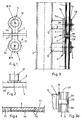
- the fastening device for vertical and inclined glass facade cladding (1) takes place by means of on the building structure (building wall, roof, wall steps or the like.) Definable support structure (2) and thereon arranged, the facade cladding (1) at a distance from Support structure (2) supporting holders (3) as Glazing bracket.
- Each holder (3) is from one to the Support structure (2) with spaced shield (4) with at least one two horizontally adjacent isolider glass panes (Facade panes) (1a, 1b) on both sides of their vertical joint (F2) comprehensive clamping plate (5) and a horizontally aligned under the two horizontal facade panes (1a, 1b) and formed this carrying sword (6).
- the shield (4) is an elongated, vertically oriented Bearing shield formed, has one at both ends two adjacent horizontal facade panes (1a, 1b) on both sides their joint (F2) overlapping clamping plate (5) on and there is a horizontal between the two clamping plates (5) aligned, in the horizontal joint (F1) of four colliding facade panes (1a, 1b, 1c, 1d) and the two upper facade panes arranged side by side - Insulating glass panes (1a, 1b) - carrying sword (6).
- FIG. 5 From Fig. 5 it can be seen that the top two, side by side facade panes (1a, 1b) lying in the horizontal joint (F1) carried by the sword (6) by the sword (6) in this joint (F1) engages and under the bottom (UK) of the two Facade panes (1a, 1b).
- the two below, facade panes (1c, 1d) lying next to each other lie with their Top (OK) with a small distance (air, play) under the Sword (6) and are also under one of their bottom (UK) cross sword (6) carried by another holder (3).
- Each clamping plate (5) has one at the respective length end of the the structure or the supporting structure (2) adjacent shield (4) molded disc-shaped contact plate (5a) on which the Facade panes (1) with the interposition of a seal (7) concern, and he has a second, with interposition a seal (8) against the outside (AS) of the facade panes (1) acting, disc-shaped clamping plate (5b), and both Plates (5a, 5b) are formed by a vertical joint (F2) adjacent facade pane (1a, 1b, 1c, 1d) comprehensive Screw connection (8, 9) clamped together.
- F2 vertical joint
- each clamping plate (5) consists of one bolts (8) and one fixed on the system plate (5a) on the protruding from the clamping plate (5b)
- the facade panes (1) are each interposed a seal (11) with its underside (UK) on the sword (6) on (Fig. 3 and 5).
- the elongated flat, web or strip-shaped sign (4) has the shape of a with the two end clamping plates (5) Dumbbell as shown in Fig. 1.
- the sword (6) is a stainless steel sword of an elongated one Web (bar) formed with an angular, such as rectangular, cross section, which on the side facing the facade pane (1) Shield (4) is fixed by welding and with the same size Length on both sides of the vertical joint (F2) the two neighboring ones Insulating glass panes (1a, 1b) almost all of them Supported pane thickness.
- the permanently elastic grouting with silicone is easy from the outside in the support sword area feasible.
- the sword (6) shows a fillet (6a) on its visible side, in which can be filled with a joint material (FM), preferably silicone, which the horizontal joints (F1) of the neighboring Facade panes (1a to 1d) filled out and without a paragraph over the Sword (6) is carried out in the region of the groove (6a), so that the sword (6) does not appear on the visible side, as shown in FIG. 4 shows.
- the vertical joints (F2) are also due to the grout (FM) filled out.
- the holder (3) is with one or both clamping plates (5) fixed to a pipe socket (12) with which the holder (3) is attached to a support tube of the support structure (2).
- FIG. 1 to 6 show the dumbbell-shaped holder (3) for the Facade pane definition in the cross area of four neighboring ones Facade panes (1), in which the two upper panes (1a, 1b) carried by the sword (6) and the holder (3) on each two adjacent upper and lower discs (1) each with a clamping plate (5) acts on both sides of the vertical Joint (F2) through the screw connection (8, 9) of the facade panes (1) with the seals (7, 8) interposed.
- the holder (3) for the vertical facade pane (1) has a short plate (4) a clamping plate (5) and at a distance below it at the end of the shield welded, bar-shaped sword (6) on which the supports vertical facade pane (1) with its lower edge (UK); this holder (3) represents half a holder.
- the inclined facade panel (1) is dumbbell-shaped Holder (3) held in the angular range on the supporting structure (2).
- Fig. 8 shows a wall-roof cladding.
- the corresponding to the Roof inclined holder (3) is half as shown in FIG. 7 Holder (3) with a clamping plate (5) and one on its short Shield (4) attached web-shaped sword (6) executed.
- the sloping facade pane (1) abuts with its underside (UK) the sword (6).
- the vertical facade panel (1) is through dumbbell-shaped holder (3) at the top and bottom of the supporting structure (2) held.
- Fig. 9 shows a roof gutter connection.
- the the top of the The facade pane (1) has fixing bracket (3) at one end only of his shield (4) a clamping plate (5), and on the shield (4) by screws (13) a vertical, reaching under the roof Connection wall (14) and a gutter (15) attached.
- FIG. 10 shows the facade cladding in the area of a structural false ceiling (16) with a dumbbell-shaped holder (3), on the Sword (6) the vertical upper facade pane (1a) which is supported by the upper clamping plate (5) in the lower Pane area is jammed.
- a multi-part support bracket (17) attached, which over the edge of the false ceiling (16) on the facade and on this is adjustable and can therefore be adjusted in height Intermediate fastening for the facade cladding (1) results.
Landscapes
- Engineering & Computer Science (AREA)
- Civil Engineering (AREA)
- Structural Engineering (AREA)
- Architecture (AREA)
- Physics & Mathematics (AREA)
- Electromagnetism (AREA)
- Load-Bearing And Curtain Walls (AREA)
- Building Environments (AREA)
Applications Claiming Priority (2)
| Application Number | Priority Date | Filing Date | Title |
|---|---|---|---|
| DE1999143525 DE19943525C2 (de) | 1999-09-11 | 1999-09-11 | Glas-Fassadenbekleidungen mit einer Befestigungsvorrichtung |
| DE19943525 | 1999-09-11 |
Publications (2)
| Publication Number | Publication Date |
|---|---|
| EP1083268A2 true EP1083268A2 (fr) | 2001-03-14 |
| EP1083268A3 EP1083268A3 (fr) | 2002-01-30 |
Family
ID=7921640
Family Applications (1)
| Application Number | Title | Priority Date | Filing Date |
|---|---|---|---|
| EP00115265A Withdrawn EP1083268A3 (fr) | 1999-09-11 | 2000-07-14 | Façade vitrée avec dispositif de fixation |
Country Status (2)
| Country | Link |
|---|---|
| EP (1) | EP1083268A3 (fr) |
| DE (1) | DE19943525C2 (fr) |
Cited By (3)
| Publication number | Priority date | Publication date | Assignee | Title |
|---|---|---|---|---|
| DE102007058931A1 (de) * | 2007-12-05 | 2009-06-18 | Köster, Helmut, Dr.-Ing. | Glasfassaden |
| DE102009020003A1 (de) | 2009-05-05 | 2010-11-11 | Köster, Helmut, Dr.-Ing. | Glasfassaden |
| US20240169103A1 (en) * | 2022-11-11 | 2024-05-23 | Alejandro Omar Labala | Bio-climatically adapted zero- energy prefabricated modular building and methods thereof with thermal bridge breakages |
Citations (1)
| Publication number | Priority date | Publication date | Assignee | Title |
|---|---|---|---|---|
| DE3843619A1 (de) | 1988-12-23 | 1990-06-28 | Amanco L & F Ag | Vorrichtung zur verkleidung eines baukoerpers im fassaden- und/oder dachbereich |
Family Cites Families (6)
| Publication number | Priority date | Publication date | Assignee | Title |
|---|---|---|---|---|
| US3685240A (en) * | 1970-03-30 | 1972-08-22 | A W Breiner | Glazing system |
| DE3838957A1 (de) * | 1988-11-17 | 1990-05-23 | Forster Ag Hermann | Isolierende verbindungsvorrichtung fuer bauplatten |
| CH679054A5 (en) * | 1989-09-21 | 1991-12-13 | Diethelm Ag Metallbau | Facade structure - has insulating components securing both window inserts and their covering members to beams |
| DE9305802U1 (de) * | 1993-04-19 | 1993-08-26 | Herzog, Thomas, Prof. Dr., 80805 München | Konsole zur Halterung von flächigen Bauteilen, insbesondere Glasscheiben |
| DE9405964U1 (de) * | 1994-04-11 | 1994-06-16 | Staba Wuppermann GmbH, 51381 Leverkusen | Fassade |
| FR2739406B1 (fr) * | 1995-09-29 | 1999-01-08 | Saint Gobain Vitrage | Dispositif de fixation de vitrages sur une structure porteuse |
-
1999
- 1999-09-11 DE DE1999143525 patent/DE19943525C2/de not_active Expired - Fee Related
-
2000
- 2000-07-14 EP EP00115265A patent/EP1083268A3/fr not_active Withdrawn
Patent Citations (1)
| Publication number | Priority date | Publication date | Assignee | Title |
|---|---|---|---|---|
| DE3843619A1 (de) | 1988-12-23 | 1990-06-28 | Amanco L & F Ag | Vorrichtung zur verkleidung eines baukoerpers im fassaden- und/oder dachbereich |
Cited By (3)
| Publication number | Priority date | Publication date | Assignee | Title |
|---|---|---|---|---|
| DE102007058931A1 (de) * | 2007-12-05 | 2009-06-18 | Köster, Helmut, Dr.-Ing. | Glasfassaden |
| DE102009020003A1 (de) | 2009-05-05 | 2010-11-11 | Köster, Helmut, Dr.-Ing. | Glasfassaden |
| US20240169103A1 (en) * | 2022-11-11 | 2024-05-23 | Alejandro Omar Labala | Bio-climatically adapted zero- energy prefabricated modular building and methods thereof with thermal bridge breakages |
Also Published As
| Publication number | Publication date |
|---|---|
| DE19943525A1 (de) | 2001-04-12 |
| EP1083268A3 (fr) | 2002-01-30 |
| DE19943525C2 (de) | 2003-04-24 |
Similar Documents
| Publication | Publication Date | Title |
|---|---|---|
| EP2354368B1 (fr) | Etrier de fixation pour isolations murales | |
| EP0658666B1 (fr) | Système de fixation pour plaques de façade | |
| DE19636165B4 (de) | Fassade | |
| DE4209834C2 (de) | Glasfassade an einer Tragstruktur | |
| DE69612251T2 (de) | Haltevorrichtung für ein, gegenüber der vertikalen Fassade einer Vorhängewand eines Gebäudes oder ähnlichen Konstruktion, freitragendes Element | |
| AT411697B (de) | Glasfassade aus rahmenlos verlegten glastafeln | |
| DE20312122U1 (de) | Vorgehängte Fassadenkonstruktion | |
| EP3473773B1 (fr) | Élément de paroi destiné à l'utilisation dans un dispositif de rétention d'eau ainsi que dispositif de rétention d'eau | |
| EP0411442A2 (fr) | Dispositif pour soutenir des plaques suspendues en pierre pour le revêtement des façades | |
| DE19943525C2 (de) | Glas-Fassadenbekleidungen mit einer Befestigungsvorrichtung | |
| DE20010299U1 (de) | Fassaden- und/oder Lichtdachkonstruktion und Montagevorrichtung zum Befestigen von Sonnenkollektoren an einer Fassaden- und/oder Lichtdachkonstruktion | |
| CH672344A5 (fr) | ||
| DE2617328A1 (de) | Vorrichtung zum anbringen von vertikalen rauchfang-wandplatten an/unterhalb der decke eines raumes | |
| AT401788B (de) | Fassade | |
| AT409510B (de) | Wand- und fassaden-system | |
| DE202013105120U1 (de) | Carport | |
| DE9305802U1 (de) | Konsole zur Halterung von flächigen Bauteilen, insbesondere Glasscheiben | |
| DE10110802B4 (de) | Fassadenverkleidung | |
| EP2518233B1 (fr) | Élément porteur en verre | |
| DE10242423B3 (de) | Stütze für das Bauwesen | |
| DE4204638A1 (de) | Vorrichtung zur schalldaemmung in raeumen | |
| DE202006019031U1 (de) | Modulares Tragsystem für Solarkollektoren | |
| DE102010027368A1 (de) | Vorrichtung zur Eckbefestigung einer Leibungsplatte | |
| DE202012001635U1 (de) | Gebäudewand mit Glaselementen | |
| DE9207858U1 (de) | Dachrinne |
Legal Events
| Date | Code | Title | Description |
|---|---|---|---|
| PUAI | Public reference made under article 153(3) epc to a published international application that has entered the european phase |
Free format text: ORIGINAL CODE: 0009012 |
|
| AK | Designated contracting states |
Kind code of ref document: A2 Designated state(s): AT BE CH CY DE DK ES FI FR GB GR IE IT LI LU MC NL PT SE |
|
| AX | Request for extension of the european patent |
Free format text: AL;LT;LV;MK;RO;SI |
|
| PUAL | Search report despatched |
Free format text: ORIGINAL CODE: 0009013 |
|
| AK | Designated contracting states |
Kind code of ref document: A3 Designated state(s): AT BE CH CY DE DK ES FI FR GB GR IE IT LI LU MC NL PT SE |
|
| AX | Request for extension of the european patent |
Free format text: AL;LT;LV;MK;RO;SI |
|
| AKX | Designation fees paid | ||
| REG | Reference to a national code |
Ref country code: DE Ref legal event code: 8566 |
|
| STAA | Information on the status of an ep patent application or granted ep patent |
Free format text: STATUS: THE APPLICATION IS DEEMED TO BE WITHDRAWN |
|
| 18D | Application deemed to be withdrawn |
Effective date: 20020731 |