EP1083339A2 - Kunststoff-Befestigungsvorrichtung - Google Patents
Kunststoff-Befestigungsvorrichtung Download PDFInfo
- Publication number
- EP1083339A2 EP1083339A2 EP00118563A EP00118563A EP1083339A2 EP 1083339 A2 EP1083339 A2 EP 1083339A2 EP 00118563 A EP00118563 A EP 00118563A EP 00118563 A EP00118563 A EP 00118563A EP 1083339 A2 EP1083339 A2 EP 1083339A2
- Authority
- EP
- European Patent Office
- Prior art keywords
- shaft
- plastic
- fastening device
- fastening element
- blank
- Prior art date
- Legal status (The legal status is an assumption and is not a legal conclusion. Google has not performed a legal analysis and makes no representation as to the accuracy of the status listed.)
- Granted
Links
- 229920002994 synthetic fiber Polymers 0.000 title 1
- 239000004033 plastic Substances 0.000 claims abstract description 29
- 239000000463 material Substances 0.000 claims abstract description 12
- 238000010438 heat treatment Methods 0.000 claims description 9
- 230000003446 memory effect Effects 0.000 claims description 9
- 238000001746 injection moulding Methods 0.000 claims description 6
- 238000004873 anchoring Methods 0.000 claims description 5
- 229920000098 polyolefin Polymers 0.000 claims description 2
- 238000002347 injection Methods 0.000 abstract description 4
- 239000007924 injection Substances 0.000 abstract description 4
- 0 CCNC(C)[C@](C)* Chemical compound CCNC(C)[C@](C)* 0.000 description 4
- 238000002425 crystallisation Methods 0.000 description 4
- 230000008025 crystallization Effects 0.000 description 4
- 238000000034 method Methods 0.000 description 3
- 238000001816 cooling Methods 0.000 description 2
- 238000004519 manufacturing process Methods 0.000 description 2
- 239000002991 molded plastic Substances 0.000 description 2
- 238000007493 shaping process Methods 0.000 description 2
- FUUGBGSHEIEQMS-UHFFFAOYSA-N CC1(CCCC2)C2(C)CCCC1 Chemical compound CC1(CCCC2)C2(C)CCCC1 FUUGBGSHEIEQMS-UHFFFAOYSA-N 0.000 description 1
- 241001417534 Lutjanidae Species 0.000 description 1
- 238000005516 engineering process Methods 0.000 description 1
- 230000005855 radiation Effects 0.000 description 1
- 239000000126 substance Substances 0.000 description 1
Images
Classifications
-
- F—MECHANICAL ENGINEERING; LIGHTING; HEATING; WEAPONS; BLASTING
- F16—ENGINEERING ELEMENTS AND UNITS; GENERAL MEASURES FOR PRODUCING AND MAINTAINING EFFECTIVE FUNCTIONING OF MACHINES OR INSTALLATIONS; THERMAL INSULATION IN GENERAL
- F16B—DEVICES FOR FASTENING OR SECURING CONSTRUCTIONAL ELEMENTS OR MACHINE PARTS TOGETHER, e.g. NAILS, BOLTS, CIRCLIPS, CLAMPS, CLIPS OR WEDGES; JOINTS OR JOINTING
- F16B33/00—Features common to bolt and nut
- F16B33/006—Non-metallic fasteners using screw-thread
-
- C—CHEMISTRY; METALLURGY
- C08—ORGANIC MACROMOLECULAR COMPOUNDS; THEIR PREPARATION OR CHEMICAL WORKING-UP; COMPOSITIONS BASED THEREON
- C08L—COMPOSITIONS OF MACROMOLECULAR COMPOUNDS
- C08L2201/00—Properties
- C08L2201/12—Shape memory
-
- F—MECHANICAL ENGINEERING; LIGHTING; HEATING; WEAPONS; BLASTING
- F16—ENGINEERING ELEMENTS AND UNITS; GENERAL MEASURES FOR PRODUCING AND MAINTAINING EFFECTIVE FUNCTIONING OF MACHINES OR INSTALLATIONS; THERMAL INSULATION IN GENERAL
- F16B—DEVICES FOR FASTENING OR SECURING CONSTRUCTIONAL ELEMENTS OR MACHINE PARTS TOGETHER, e.g. NAILS, BOLTS, CIRCLIPS, CLAMPS, CLIPS OR WEDGES; JOINTS OR JOINTING
- F16B2200/00—Constructional details of connections not covered for in other groups of this subclass
- F16B2200/77—Use of a shape-memory material
Definitions
- the invention relates to a plastic fastening device for fastening a first part on a second part by means of anchoring in a recess in at least one of the two parts.
- Plastic fasteners in the form of screws, rivets, expansion anchors and snappers are known in a wide variety of configurations. Such fasteners are used in a variety of applications used to attach two parts. These are fasteners through a recess (e.g. bore) of the first part inserted into a corresponding recess in the second part, where they are then held mechanically.
- a recess e.g. bore
- the invention is therefore based on the object of a plastic fastening device to create oneself in a simple way with little effort can be solved again, if, for example, in the case of the recyclability of Products is required.
- the starting product of the plastic fastening device according to the invention is a fastening element made of an injection-molded plastic part made of a plastic material with a memory effect, which in the simplest case has only one shaft.
- the fastener is a pin, bolt, etc.
- the cross-sectional area of the shaft of the fastening element produced by injection molding is smaller in its initial state after injection molding than the cross-sectional area of the recess or recesses into which the fastening element is inserted for the purpose of fastening two parts.
- the fastening element or the shaft of the fastening element is deformed in such a way that its cross-sectional area now has regions that project beyond the cross-sectional area of the recess or recesses.
- the heated deformed fastening element is then cooled.
- the deformed fastener retains its shape given by the hot working.
- This shape can be, for example, a thread that is formed on the outside of the shaft.
- At least one or preferably both ends of the shaft can be widened
- a third possibility is to provide projections on the shaft other than that of a thread, so that the shaft has latching elements which can be locked with the recess of the parts and which protrude radially from the shaft and, in the manner of barbs, the fastening element in the Anchoring the recess
- Another option is to design the fastener after hot forming as fir tree-like "anchoring element to see.
- thermoformed plastic fastener with memory effect consists in the deformability by heating the Fastener. Then namely the shape of the fastener back to its original state; The previously with the Recess or hooked with the cutouts of the two parts or these Recessing projections of the shaft thus form automatically back, so that the cross-sectional area of the shaft to a measure shrinks, which is smaller than the cross-sectional area of the recess.
- the fastener in a simple manner from the or remove the recesses.
- the fastener of an elevated temperature suspend that above the crystallization temperature of the plastic lies. This greatly simplifies the process of separating both parts and prevents in particular that with the fastener according to the invention connected parts must be destroyed in order to be separated to become.
- the material for the fastening element of the plastic fastening device is particularly polyolefin that networked or not networked.
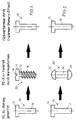
- the embodiment of the invention according to FIG. 1 is about the manufacture a plastic screw by hot forming a blank.
- a pin 10 which is T-shaped in side view, which has a shaft 12 and a widened head piece 14.
- the shaft 12 has a smaller diameter than the bore or recess, for which the bolt 10 is provided.
- the bolt 10 is around a plastic injection molded part made of PEX material.
- the blank is then heated and, when heated, becomes one Screw deformed. This means that the shaft 12 is now with one External thread 16 is provided, while the head 14 with a slot or cross slot 18 is provided. After heating and deformation of the The blank is cooled while maintaining its deformation. The Cooling takes place in the hot press mold. After cooling, arises So then a screw fastener 20 that lasts as long as its Temperature not above the crystallization temperature of the plastic material maintains its shape.
- the screw fastener 20 can now be screwed on first part can be used on a second part.
- the thread 16 acts with a corresponding thread on one of the two parts or just together with the hole edge of one of the two parts.
- FIG. 2 shows an alternative embodiment of a fastening element according to the invention shown.
- the starting point is again a blank 10, the has a shaft 12 and a widened head piece 14.
- This blank 10 is formed by hot forming into a rivet fastening element 20 ', the two lens head-like ends 22 and a shaft 24 in between having.
- This rivet fastening element 20 ' can now be used for fastening or Connecting two parts are used, with its shaft 24 through two corresponding holes or recesses in the to be connected Sharing stretches.
- the deformed screw or rivet fasteners 20, 20 'according to Fig. 1 and 2 can be reused insofar as they are the starting product can be for a new hot forming. With that the fasteners described here or the predecessor products (Blanks) can also be recycled, which is an advantage.
- the starting product i.e. the injection molded plastic fastening element not necessarily as previously described and shown in the drawing needs to be trained. So a (cylindrical) pin or bolt can also be used Element that only has a shaft without a widened head part.
Landscapes
- Engineering & Computer Science (AREA)
- General Engineering & Computer Science (AREA)
- Mechanical Engineering (AREA)
- Injection Moulding Of Plastics Or The Like (AREA)
- Insertion Pins And Rivets (AREA)
- Moulds For Moulding Plastics Or The Like (AREA)
- Basic Packing Technique (AREA)
- Manufacturing And Processing Devices For Dough (AREA)
- Lining Or Joining Of Plastics Or The Like (AREA)
Abstract
Description
- einem in Kunststoffspritzgusstechnik hergestellten Befestigungselement aus einem Kunststoff-Material mit Memory-Effekt mit einem Schaft und einem Kopfstück, wobei
- der Schaft in seinem Ausgangszustand nach dem Spritzgießen eine kleinere Querschnittsfläche aufweist als die Aussparung,
- zumindest der Schaft in erwärmtem Zustand derart verformt wird, dass er über die Querschnittsfläche der Aussparung überstehende Bereiche aufweist, und
- der Schaft im so verformten Zustand abgekühlt wird,
- so dass der Schaft durch Erwärmung aufgrund des Memory-Effekts in seinen Ausgangszustand zurückformbar ist.

- Fig. 1
- den Umformvorgang zum Umformen eines gespritzten Befestigungselement-Rohlings zu einer Kunststoffschraube und deren Rückverformung zum Rohling nach einer Erwärmung und
- Fig. 2
- ähnlich Fig. 1 die Umformung des Rohlings in einen Niet und dessen Rückumformung in den Rohling nach Erwärmung aufgrund des Memory-Effekts.
Claims (4)
- Kunststoff-Befestigungsvorrichtung zur Befestigung eines ersten Teils an einem zweiten Teil mittels Verankerung in einer Aussparung in mindestens einem der beiden Teile, miteinem in Kunststoffspritzgusstechnik hergestellten Befestigungselement (20;20') aus einem Kunststoff-Material mit Memory-Effekt mit einem Schaft (12), wobeider Schaft (12) in seinem Ausgangszustand nach dem Spritzgießen eine kleinere Querschnittsfläche aufweist als die Aussparung,zumindest der Schaft (12) in erwärmtem Zustand derart verformt wird, dass er über die Querschnittsfläche der Aussparung überstehende Bereiche (16,22) aufweist, undder Schaft (12) im so verformten Zustand abgekühlt wird,so dass der Schaft (12) durch Erwärmung aufgrund des Memory-Effekts in seinen Ausgangszustand zurückformbar ist.
- Kunststoff-Befestigungsvorrichtung nach Anspruch 1, dadurch gekennzeichnet, dass das Befestigungselement (20;20') ein vernetztes oder unvernetztes Polyolefin, insbesondere PEX aufweist.
- Kunststoff-Befestigungsvorrichtung nach Anspruch 1 oder 2, dadurch gekennzeichnet, dass die Verformung des Schafts (12) an dessen Außenfläche in Form mindestens eines Vorsprungs, insbesondere eines Gewindes (16) erfolgt.
- Kunststoff-Befestigungsvorrichtung nach Anspruch 1 oder 2, dadurch gekennzeichnet, dass die Verformung des Schafts (12) an mindestens einem seiner beiden Enden in Form einer Verbreiterung (22) erfolgt.
Applications Claiming Priority (2)
| Application Number | Priority Date | Filing Date | Title |
|---|---|---|---|
| DE19942829 | 1999-09-08 | ||
| DE19942829 | 1999-09-08 |
Publications (3)
| Publication Number | Publication Date |
|---|---|
| EP1083339A2 true EP1083339A2 (de) | 2001-03-14 |
| EP1083339A3 EP1083339A3 (de) | 2002-06-05 |
| EP1083339B1 EP1083339B1 (de) | 2004-09-22 |
Family
ID=7921183
Family Applications (1)
| Application Number | Title | Priority Date | Filing Date |
|---|---|---|---|
| EP00118563A Expired - Lifetime EP1083339B1 (de) | 1999-09-08 | 2000-08-26 | Kunststoff-Befestigungsvorrichtung |
Country Status (3)
| Country | Link |
|---|---|
| EP (1) | EP1083339B1 (de) |
| AT (1) | ATE277291T1 (de) |
| DE (1) | DE50007858D1 (de) |
Cited By (2)
| Publication number | Priority date | Publication date | Assignee | Title |
|---|---|---|---|---|
| WO2002068831A1 (de) * | 2001-02-26 | 2002-09-06 | Siemens Aktiengesellschaft | Montageelement zum verbinden zweier gegenstände |
| WO2008106997A1 (de) * | 2007-03-07 | 2008-09-12 | Siemens Aktiengesellschaft | Verbindungsvorrichtung und verfahren zum herstellen einer verbindung |
Family Cites Families (4)
| Publication number | Priority date | Publication date | Assignee | Title |
|---|---|---|---|---|
| JP3019419B2 (ja) * | 1990-12-26 | 2000-03-13 | 住友金属工業株式会社 | 形状記憶性ポリオレフィン樹脂組成物 |
| JPH0610926A (ja) * | 1992-06-24 | 1994-01-21 | Hitachi Ltd | 装置あるいは設備の部品接合及び解体方式 |
| JP3292222B2 (ja) * | 1993-10-14 | 2002-06-17 | 松下電器産業株式会社 | 結合子とその結合方法及び結合装置 |
| GB2320277B (en) * | 1996-12-09 | 2001-10-10 | Univ Brunel | Improvements relating to product disassembly |
-
2000
- 2000-08-26 AT AT00118563T patent/ATE277291T1/de not_active IP Right Cessation
- 2000-08-26 DE DE50007858T patent/DE50007858D1/de not_active Expired - Lifetime
- 2000-08-26 EP EP00118563A patent/EP1083339B1/de not_active Expired - Lifetime
Non-Patent Citations (1)
| Title |
|---|
| None |
Cited By (2)
| Publication number | Priority date | Publication date | Assignee | Title |
|---|---|---|---|---|
| WO2002068831A1 (de) * | 2001-02-26 | 2002-09-06 | Siemens Aktiengesellschaft | Montageelement zum verbinden zweier gegenstände |
| WO2008106997A1 (de) * | 2007-03-07 | 2008-09-12 | Siemens Aktiengesellschaft | Verbindungsvorrichtung und verfahren zum herstellen einer verbindung |
Also Published As
| Publication number | Publication date |
|---|---|
| EP1083339A3 (de) | 2002-06-05 |
| EP1083339B1 (de) | 2004-09-22 |
| DE50007858D1 (de) | 2004-10-28 |
| ATE277291T1 (de) | 2004-10-15 |
Similar Documents
| Publication | Publication Date | Title |
|---|---|---|
| DE69920788T2 (de) | Befestigung von Zuzammenbauten auf einem tragenden Element | |
| DE3420263C2 (de) | ||
| DE102007047860B3 (de) | Verbindungselement mit einer Schraube und einer daran unverlierbar angeordneten Hülse | |
| DE69004184T2 (de) | Geschichteter Mutternkäfig mit ineinander verrasteten Fingern und Verfahren zu seiner Herstellung. | |
| DE60211359T2 (de) | Schnellbefestigungssystem für kunststoffteile | |
| EP1134438A2 (de) | Verbindungsanordnung zum Anbringen eines Befestigungselementes an einem Bauteil | |
| DE3042139A1 (de) | Befestigungsanordnung | |
| DE102015121893A1 (de) | Verfahren zur Herstellung eines Anschlags für eine Rohrmontagevorrichtung und Anschlag | |
| DE69608002T2 (de) | Verfahren zum Befestigen von Bauteilen einer Zusammenstellung | |
| DE3915732C2 (de) | Verbindungsanordnung | |
| DE3507966A1 (de) | Selbstverriegelndes blind-befestigungselement | |
| DE112007002638T5 (de) | Verbesserungen an Befestigungsmitteln | |
| DE102009024264A1 (de) | Befestigungselement, insbesondere Mutter | |
| EP3508737B1 (de) | Verbindungsanordnung für scheinwerferkomponenten | |
| DE3429585A1 (de) | Aus einem kunststoffspreizduebel und einer befestigungsschraube bestehender befestigungssatz | |
| DE19954912C2 (de) | Vorrichtung aus Platte und Bolzen | |
| EP1083339B1 (de) | Kunststoff-Befestigungsvorrichtung | |
| DE602004000741T2 (de) | Einlegeteilspritzgiessverfahren und Einlegeteilspannelement | |
| DE102013224459A1 (de) | Verbindungseinrichtung umfassend eine Abstandsbuchse und eine Schraube | |
| DE102009055861A1 (de) | Abdeckung von Schraubenbohrungen | |
| EP2037130A1 (de) | Befestigungsmittel | |
| DE19912068B4 (de) | Wellen- oder Stellmutter und Verfahren zu ihrer Herstellung | |
| DE19531016C2 (de) | Verbindungselement, nach Art eines Niets | |
| EP3077683B1 (de) | Spreizdübel mit spreizbereich mit einstichen | |
| EP1948945B1 (de) | Montageschraube zur befestigung von beschlagteilen, insbesondere von bandteilen an hohlkammerprofilen |
Legal Events
| Date | Code | Title | Description |
|---|---|---|---|
| PUAI | Public reference made under article 153(3) epc to a published international application that has entered the european phase |
Free format text: ORIGINAL CODE: 0009012 |
|
| AK | Designated contracting states |
Kind code of ref document: A2 Designated state(s): AT BE CH CY DE DK ES FI FR GB GR IE IT LI LU MC NL PT SE |
|
| AX | Request for extension of the european patent |
Free format text: AL;LT;LV;MK;RO;SI |
|
| RAP1 | Party data changed (applicant data changed or rights of an application transferred) |
Owner name: UPONOR INNOVATION AB |
|
| PUAL | Search report despatched |
Free format text: ORIGINAL CODE: 0009013 |
|
| AK | Designated contracting states |
Kind code of ref document: A3 Designated state(s): AT BE CH CY DE DK ES FI FR GB GR IE IT LI LU MC NL PT SE |
|
| AX | Request for extension of the european patent |
Free format text: AL;LT;LV;MK;RO;SI |
|
| 17P | Request for examination filed |
Effective date: 20021204 |
|
| AKX | Designation fees paid |
Designated state(s): AT BE CH CY DE DK ES FI FR GB GR IE IT LI LU MC NL PT SE |
|
| GRAP | Despatch of communication of intention to grant a patent |
Free format text: ORIGINAL CODE: EPIDOSNIGR1 |
|
| GRAS | Grant fee paid |
Free format text: ORIGINAL CODE: EPIDOSNIGR3 |
|
| GRAA | (expected) grant |
Free format text: ORIGINAL CODE: 0009210 |
|
| AK | Designated contracting states |
Kind code of ref document: B1 Designated state(s): AT BE CH CY DE DK ES FI FR GB GR IE IT LI LU MC NL PT SE |
|
| PG25 | Lapsed in a contracting state [announced via postgrant information from national office to epo] |
Ref country code: IT Free format text: LAPSE BECAUSE OF FAILURE TO SUBMIT A TRANSLATION OF THE DESCRIPTION OR TO PAY THE FEE WITHIN THE PRESCRIBED TIME-LIMIT;WARNING: LAPSES OF ITALIAN PATENTS WITH EFFECTIVE DATE BEFORE 2007 MAY HAVE OCCURRED AT ANY TIME BEFORE 2007. THE CORRECT EFFECTIVE DATE MAY BE DIFFERENT FROM THE ONE RECORDED. Effective date: 20040922 Ref country code: GB Free format text: LAPSE BECAUSE OF FAILURE TO SUBMIT A TRANSLATION OF THE DESCRIPTION OR TO PAY THE FEE WITHIN THE PRESCRIBED TIME-LIMIT Effective date: 20040922 Ref country code: NL Free format text: LAPSE BECAUSE OF FAILURE TO SUBMIT A TRANSLATION OF THE DESCRIPTION OR TO PAY THE FEE WITHIN THE PRESCRIBED TIME-LIMIT Effective date: 20040922 Ref country code: FI Free format text: LAPSE BECAUSE OF FAILURE TO SUBMIT A TRANSLATION OF THE DESCRIPTION OR TO PAY THE FEE WITHIN THE PRESCRIBED TIME-LIMIT Effective date: 20040922 Ref country code: FR Free format text: LAPSE BECAUSE OF FAILURE TO SUBMIT A TRANSLATION OF THE DESCRIPTION OR TO PAY THE FEE WITHIN THE PRESCRIBED TIME-LIMIT Effective date: 20040922 Ref country code: IE Free format text: LAPSE BECAUSE OF FAILURE TO SUBMIT A TRANSLATION OF THE DESCRIPTION OR TO PAY THE FEE WITHIN THE PRESCRIBED TIME-LIMIT Effective date: 20040922 |
|
| REG | Reference to a national code |
Ref country code: GB Ref legal event code: FG4D Free format text: NOT ENGLISH |
|
| REG | Reference to a national code |
Ref country code: CH Ref legal event code: EP |
|
| REG | Reference to a national code |
Ref country code: IE Ref legal event code: FG4D Free format text: GERMAN |
|
| REF | Corresponds to: |
Ref document number: 50007858 Country of ref document: DE Date of ref document: 20041028 Kind code of ref document: P |
|
| PG25 | Lapsed in a contracting state [announced via postgrant information from national office to epo] |
Ref country code: GR Free format text: LAPSE BECAUSE OF FAILURE TO SUBMIT A TRANSLATION OF THE DESCRIPTION OR TO PAY THE FEE WITHIN THE PRESCRIBED TIME-LIMIT Effective date: 20041222 Ref country code: SE Free format text: LAPSE BECAUSE OF FAILURE TO SUBMIT A TRANSLATION OF THE DESCRIPTION OR TO PAY THE FEE WITHIN THE PRESCRIBED TIME-LIMIT Effective date: 20041222 Ref country code: DK Free format text: LAPSE BECAUSE OF FAILURE TO SUBMIT A TRANSLATION OF THE DESCRIPTION OR TO PAY THE FEE WITHIN THE PRESCRIBED TIME-LIMIT Effective date: 20041222 |
|
| PG25 | Lapsed in a contracting state [announced via postgrant information from national office to epo] |
Ref country code: ES Free format text: LAPSE BECAUSE OF FAILURE TO SUBMIT A TRANSLATION OF THE DESCRIPTION OR TO PAY THE FEE WITHIN THE PRESCRIBED TIME-LIMIT Effective date: 20050102 |
|
| REG | Reference to a national code |
Ref country code: CH Ref legal event code: NV Representative=s name: HEPP, WENGER & RYFFEL AG |
|
| NLV1 | Nl: lapsed or annulled due to failure to fulfill the requirements of art. 29p and 29m of the patents act | ||
| GBV | Gb: ep patent (uk) treated as always having been void in accordance with gb section 77(7)/1977 [no translation filed] |
Effective date: 20040922 |
|
| REG | Reference to a national code |
Ref country code: IE Ref legal event code: FD4D |
|
| PLBE | No opposition filed within time limit |
Free format text: ORIGINAL CODE: 0009261 |
|
| STAA | Information on the status of an ep patent application or granted ep patent |
Free format text: STATUS: NO OPPOSITION FILED WITHIN TIME LIMIT |
|
| PG25 | Lapsed in a contracting state [announced via postgrant information from national office to epo] |
Ref country code: LU Free format text: LAPSE BECAUSE OF NON-PAYMENT OF DUE FEES Effective date: 20050826 Ref country code: AT Free format text: LAPSE BECAUSE OF NON-PAYMENT OF DUE FEES Effective date: 20050826 Ref country code: CY Free format text: LAPSE BECAUSE OF FAILURE TO SUBMIT A TRANSLATION OF THE DESCRIPTION OR TO PAY THE FEE WITHIN THE PRESCRIBED TIME-LIMIT Effective date: 20050826 |
|
| PG25 | Lapsed in a contracting state [announced via postgrant information from national office to epo] |
Ref country code: BE Free format text: LAPSE BECAUSE OF NON-PAYMENT OF DUE FEES Effective date: 20050831 Ref country code: MC Free format text: LAPSE BECAUSE OF NON-PAYMENT OF DUE FEES Effective date: 20050831 |
|
| 26N | No opposition filed |
Effective date: 20050623 |
|
| EN | Fr: translation not filed | ||
| BERE | Be: lapsed |
Owner name: *UPONOR INNOVATION A.B. Effective date: 20050831 |
|
| PG25 | Lapsed in a contracting state [announced via postgrant information from national office to epo] |
Ref country code: PT Free format text: LAPSE BECAUSE OF NON-PAYMENT OF DUE FEES Effective date: 20050222 |
|
| PGFP | Annual fee paid to national office [announced via postgrant information from national office to epo] |
Ref country code: CH Payment date: 20080717 Year of fee payment: 9 |
|
| REG | Reference to a national code |
Ref country code: CH Ref legal event code: PL |
|
| PG25 | Lapsed in a contracting state [announced via postgrant information from national office to epo] |
Ref country code: CH Free format text: LAPSE BECAUSE OF NON-PAYMENT OF DUE FEES Effective date: 20090831 Ref country code: LI Free format text: LAPSE BECAUSE OF NON-PAYMENT OF DUE FEES Effective date: 20090831 |
|
| PGFP | Annual fee paid to national office [announced via postgrant information from national office to epo] |
Ref country code: DE Payment date: 20100823 Year of fee payment: 11 |
|
| REG | Reference to a national code |
Ref country code: DE Ref legal event code: R119 Ref document number: 50007858 Country of ref document: DE Effective date: 20120301 |
|
| PG25 | Lapsed in a contracting state [announced via postgrant information from national office to epo] |
Ref country code: DE Free format text: LAPSE BECAUSE OF NON-PAYMENT OF DUE FEES Effective date: 20120301 |