EP1083360A2 - Dispositif et procédé pour déterminer la température d'un élément de frein monté sur un véhicule - Google Patents
Dispositif et procédé pour déterminer la température d'un élément de frein monté sur un véhicule Download PDFInfo
- Publication number
- EP1083360A2 EP1083360A2 EP00118299A EP00118299A EP1083360A2 EP 1083360 A2 EP1083360 A2 EP 1083360A2 EP 00118299 A EP00118299 A EP 00118299A EP 00118299 A EP00118299 A EP 00118299A EP 1083360 A2 EP1083360 A2 EP 1083360A2
- Authority
- EP
- European Patent Office
- Prior art keywords
- vehicle
- brake
- determining
- braking element
- temperature
- Prior art date
- Legal status (The legal status is an assumption and is not a legal conclusion. Google has not performed a legal analysis and makes no representation as to the accuracy of the status listed.)
- Granted
Links
- 238000000034 method Methods 0.000 title claims abstract description 42
- 238000012545 processing Methods 0.000 claims abstract description 36
- 238000005381 potential energy Methods 0.000 claims description 10
- 230000005855 radiation Effects 0.000 claims description 6
- 230000033001 locomotion Effects 0.000 claims description 5
- 238000012546 transfer Methods 0.000 description 16
- 230000006870 function Effects 0.000 description 14
- 238000001816 cooling Methods 0.000 description 9
- 239000003570 air Substances 0.000 description 5
- 238000004364 calculation method Methods 0.000 description 5
- 230000001419 dependent effect Effects 0.000 description 3
- 238000011161 development Methods 0.000 description 3
- 230000018109 developmental process Effects 0.000 description 3
- 230000001133 acceleration Effects 0.000 description 2
- 230000000694 effects Effects 0.000 description 2
- 239000000779 smoke Substances 0.000 description 2
- 239000000725 suspension Substances 0.000 description 2
- 230000006978 adaptation Effects 0.000 description 1
- 239000012080 ambient air Substances 0.000 description 1
- 238000013459 approach Methods 0.000 description 1
- 230000005540 biological transmission Effects 0.000 description 1
- 230000006735 deficit Effects 0.000 description 1
- 238000010586 diagram Methods 0.000 description 1
- 230000005520 electrodynamics Effects 0.000 description 1
- 238000011156 evaluation Methods 0.000 description 1
- 230000010354 integration Effects 0.000 description 1
- 238000004519 manufacturing process Methods 0.000 description 1
- 239000011159 matrix material Substances 0.000 description 1
- 239000000203 mixture Substances 0.000 description 1
- 238000003825 pressing Methods 0.000 description 1
- 239000010453 quartz Substances 0.000 description 1
- 230000000717 retained effect Effects 0.000 description 1
- VYPSYNLAJGMNEJ-UHFFFAOYSA-N silicon dioxide Inorganic materials O=[Si]=O VYPSYNLAJGMNEJ-UHFFFAOYSA-N 0.000 description 1
- 238000012360 testing method Methods 0.000 description 1
- 230000001960 triggered effect Effects 0.000 description 1
Images





Classifications
-
- B—PERFORMING OPERATIONS; TRANSPORTING
- B60—VEHICLES IN GENERAL
- B60T—VEHICLE BRAKE CONTROL SYSTEMS OR PARTS THEREOF; BRAKE CONTROL SYSTEMS OR PARTS THEREOF, IN GENERAL; ARRANGEMENT OF BRAKING ELEMENTS ON VEHICLES IN GENERAL; PORTABLE DEVICES FOR PREVENTING UNWANTED MOVEMENT OF VEHICLES; VEHICLE MODIFICATIONS TO FACILITATE COOLING OF BRAKES
- B60T17/00—Component parts, details, or accessories of power brake systems not covered by groups B60T8/00, B60T13/00 or B60T15/00, or presenting other characteristic features
- B60T17/18—Safety devices; Monitoring
- B60T17/22—Devices for monitoring or checking brake systems; Signal devices
-
- F—MECHANICAL ENGINEERING; LIGHTING; HEATING; WEAPONS; BLASTING
- F16—ENGINEERING ELEMENTS AND UNITS; GENERAL MEASURES FOR PRODUCING AND MAINTAINING EFFECTIVE FUNCTIONING OF MACHINES OR INSTALLATIONS; THERMAL INSULATION IN GENERAL
- F16D—COUPLINGS FOR TRANSMITTING ROTATION; CLUTCHES; BRAKES
- F16D66/00—Arrangements for monitoring working conditions, e.g. wear, temperature
-
- F—MECHANICAL ENGINEERING; LIGHTING; HEATING; WEAPONS; BLASTING
- F16—ENGINEERING ELEMENTS AND UNITS; GENERAL MEASURES FOR PRODUCING AND MAINTAINING EFFECTIVE FUNCTIONING OF MACHINES OR INSTALLATIONS; THERMAL INSULATION IN GENERAL
- F16D—COUPLINGS FOR TRANSMITTING ROTATION; CLUTCHES; BRAKES
- F16D66/00—Arrangements for monitoring working conditions, e.g. wear, temperature
- F16D2066/001—Temperature
-
- F—MECHANICAL ENGINEERING; LIGHTING; HEATING; WEAPONS; BLASTING
- F16—ENGINEERING ELEMENTS AND UNITS; GENERAL MEASURES FOR PRODUCING AND MAINTAINING EFFECTIVE FUNCTIONING OF MACHINES OR INSTALLATIONS; THERMAL INSULATION IN GENERAL
- F16D—COUPLINGS FOR TRANSMITTING ROTATION; CLUTCHES; BRAKES
- F16D66/00—Arrangements for monitoring working conditions, e.g. wear, temperature
- F16D2066/006—Arrangements for monitoring working conditions, e.g. wear, temperature without direct measurement of the quantity monitored, e.g. wear or temperature calculated form force and duration of braking
Definitions
- the invention relates to a device and a method for determining or Predicting the temperature of one on a wheel of a vehicle or on one Vehicle provided braking elements.
- On wheels that are intended for carrying or driving a vehicle brake elements such as brake disks are often provided, which are further Brake elements on the vehicle, such as braked by brake pads are.
- the braking element on the vehicle is braked by an actuating device brought into frictional contact with the braking element on the wheel. Due to the friction between the braking element on the wheel and the braking element on the vehicle the rotation of the wheel in relation to the vehicle is impeded, which results in braking of the vehicle relative to a road, on which the wheel rolls. Due to the friction, the brake elements are heated up and off problems arise at certain temperatures. If the intended on the wheel Brake element is formed by a brake disc, it is problematic that the surface of which is damaged when high temperatures are reached.
- Brake pads that interact with the brake disc start from Reaching an upper temperature limit to stink and smoke. At Block brakes can cause wheel damage due to the high temperatures. This is particularly problematic on subways, as the smoke and Stink the passengers annoyed and scared.
- Vehicles are mechanical brakes with a pneumatic one Actuator is provided, indispensable, because in the event of a failure provided electrodynamic brake the vehicle still reliable must be able to be braked.
- the device according to the invention has at least one wheel sensor, with whose help a current angular position of the wheel of the vehicle can be determined is.
- a wheel sensor can also be designed as an acceleration sensor, which measures the angular acceleration of the wheel, then the angular velocity and the current angular position of the wheel by a Integration process over time is determined.
- one Time base device for generating time information and a Actuating sensor provided for determining the state of the actuating device.
- the processing device processes the signals of the Wheel sensor, the weight sensor, the time base device and the Actuating sensor, wherein an additional display unit is provided with which the result of processing performed by the processing device can be output to a user of the vehicle. Deviating from that, it can Processing result can also be used to connect the vehicle to a vehicle To completely prevent further movement or to permit further movement.
- at least one point in time is determined Value for the change in the temperature of the first braking element and / or for the Change in the temperature of the second braking element compared to one previous time of determination, in which the first Brake element and / or energy supplied to the second brake element is determined becomes.
- the current kinetic energy of the vehicle is calculated and with at least one value of the value stored in the processing device kinetic energy of the vehicle at a time of determination compared to the previous point in time.
- the processing device kinetic energy of the vehicle at a time of determination compared to the previous point in time.
- Device is assumed that when scanning a Decrease in the kinetic energy of the vehicle or the decrease corresponding amount of energy as thermal energy to the first braking element and / or has been supplied to the second braking element if at the same time has not reduced the vehicle's payload and if the Actuating device for the first braking element and / or the second Brake element has been scanned.
- At least one temperature sensor is to be determined the initial temperature of the first braking element and / or the second Brake elements provided, preferably at the time of Commissioning the vehicle.
- the processing device is still like this trained that starting from the starting temperature directly or indirectly the value for the current temperature at least one determination time of the first braking element and / or the second braking element can be determined.
- the instantaneous temperature of the first braking element and / or results of the second braking element from the sum of a temperature change that the the thermal energy supplied corresponds to the brake element concerned, and the Temperature at a previous point in time or the starting temperature.
- the processing device can also be designed so that the first Braking element and / or the second braking element due to heat radiation, Heat conduction and / or convection heat energy can be determined.
- Brake discs in particular give thermal energy to them via convection ambient air. Thereby heat transfer through free and / or forced flows on the brake shoe side and on the Cooling channel area inside the brake disc must be taken into account. Moreover can heat transfer by radiation on the brake shoe side and the Cooling surface side.
- heat transfer coefficients provided the brake disc. This Values may be dependent on the current speed of the vehicle and the current temperature in the calculation Processing device determined.
- the actuation sensor for determining the state of the actuation device can be designed so that the second braking element on the first Brake element exerted force and thus the frictional force that the wheel opposes brakes the vehicle, can be determined.
- This allows additional Information about the first braking element and / or the second Brake element supplied energy when braking the vehicle gain with those determined by the change in the kinetic energy of the vehicle, energy supplied to the first braking element and / or the second braking element are comparable.
- Thermal energy gives a more precise prediction of the resultant Temperature. According to the invention, for example, from the amount of energy results from the reduction in the kinetic energy of the vehicle, and from the amount of energy resulting from the evaluation of the second Determined braking element applied to the first braking element force Mean are formed.
- the signals emitted by the height sensor from the Processing device are processable.
- the processing device can also be designed so that the potential energy of the vehicle to one Determination time using one in the processing device stored height profile of a given route of the vehicle and / or the vehicle position as a function of the signals from the wheel sensor is determinable.
- Such a device according to the invention is particularly simple built up and can be used advantageously for vehicles that are constantly on the same routes are operated. Such routes have an exact Predeterminable height profile, depending on the signals from the wheel sensor of the vehicle can be easily determined in which route section the vehicle is located. This allows an exact conclusion to be drawn draw current potential energy.
- a sensor for determining the due to the driving resistance Vehicle deprived kinetic energy can be provided.
- the driving resistance arises primarily from the friction of the wheel of the vehicle against one another the vehicle and the road as well as the air resistance of the vehicle, when it moves at a certain speed.
- the Processing device can be used to determine the driving resistance advantageously be designed so that the due to the driving resistance Using kinetic energy extracted from the vehicle Processing device stored resistance profile depending on the Signals of the wheel sensor can be determined. If both the speed of the vehicle and its absolute position on a predetermined Based on the travel distance of the vehicle, there is a map for the Driving resistance, from which the current driving resistance with knowledge of the current speed and the current absolute position of the Vehicle can be determined.
- the invention also relates to a vehicle having at least one for locomotion has provided wheel on which at least a first braking element is provided. At least one second braking element is on the vehicle itself provided for braking the vehicle by an actuator can be brought into frictional contact with the second brake element. Furthermore, one Device for determining the temperature of the first braking element and / or of the second braking element, as described above.
- the the first braking element is advantageously designed as a brake disc, while the second brake element has a brake pad.
- the inventive method makes it particularly simple and accurate determine what amount of thermal energy the first braking element and / or have been supplied to the second braking element.
- One of the invention underlying thought is based on the fact that the inaccuracies in predicting the temperature of the first braking element and / or the second Brake elements from the inaccurate determination of these brake elements supplied heat energies result. With the method according to the invention determine this thermal energy particularly precisely, so that an accurate Temperature prediction is enabled.
- the method according to the invention is also characterized by the step of Predetermining a maximum speed for a point in time after the current determination time. This is particularly advantageous if it is known that the vehicle between two times of determination of one Output speed accelerated to a maximum speed and afterwards it is slowed down again to the starting speed, as with the Operation of a subway between two consecutive stops is the case.
- the method according to the invention also provides a temperature model in the form of a Software ready to measure the temperature especially of a brake disc can be calculated without the need for a special sensor for the calculation.
- This software can be installed in the brake control electronics of a vehicle and perform a calculation every time you brake. If the temperature of the Brake disc reaches a critical value, the driver is informed by a signal communicated that either the speed to a maximum is to be reduced where there is no fear of a further rise in temperature, or the driver is given a calculated maximum speed that depending on the load of the vehicle and possibly also on Route profile of upcoming route sections is. In the latter case it can Drive the vehicle even faster with a lower charge and There is no fear of impairments to driving.
- the brake disc is supplied Energy via the kinetic energy from the change in speed within two time steps and the axle loads of the vehicle are calculated. If that The vehicle according to the invention could drive up a mountain at a time Procedures in their simplest form lead to inaccurate results because the Vehicle speed reduced without braking. For the method according to the invention still sees such cases as the scanning of a so-called braking request before, which must exist so that it is assumed is that the brake disc is energized at all. In addition can the calculated energy expenditure in the brake disc with that over the time step averaged braking request force to be compared to any mountain trips recognizable with combined braking. This leads to particularly precise results of the method according to the invention.
- Potential energy and driving resistance can also be included in the determination of the energy supplied to the brake disc, provided the required values how height profile of the route and driving resistance of the vehicle are known.
- a pressure sensor in the braking system that gives us the provides accurate pilot pressure. This can also be used for the entire Energy expenditure that flows into the pane can be calculated. About the pressure of the Brake cylinder, the transmission of the brake linkage and the coefficient of friction between Brake disc and lining can be the energy supplied to the brake disc determine.
- the determined energy difference is mostly as thermal energy in the Brake disc directed. A smaller part is from the brake pads added. This small part can be found in the compositions of the Determine the brake disc and brake pads.
- the thermal energy becomes the brake disc fed exclusively via the braking surface. From there, the Thermal energy because of the thermal conductivity of the brake disc in it Transported inside the window.
- the brake disc is preferred Embodiment of the method according to the invention arithmetically in numerous Layers of the same width are divided and one for each layer adjacent layer dependent temperature is calculated. With it become everyone Time step the exact temperatures inside the brake disc and at the Edges of the brake disc determined.
- the driver of the vehicle can use a simple signal, for example a Lamp or via a display, be informed that it is the driving speed of the Vehicle must reduce.
- the maximum driving speed can be with another simulation program for different routes and Load conditions of the vehicle can be determined. If the temperature of the Brake disc drops again, this is the device of the invention recognized and the warning signal is withdrawn again. So there is for that Vehicle no longer has a speed limit.
- a continuous speed test is also possible, in which the Driver is given a maximum speed via a display.
- This Speed is determined from the current temperature of the brake disc the load pressure (mass of the vehicle) and the upcoming route data for the next section of the vehicle's route, if any. With a subway there is a new maximum speed at every stop calculated for the next section of the route. If the route data of the The route of the subway does not exist, an average distance is specified, on the basis of which the maximum speed is determined.
- Figure 1 shows a schematic representation of a brake system according to the invention 1 of a vehicle, of which here a brake disc 2 with a brake lining 3 is shown, which can be actuated by a brake cylinder 4.
- the brake cylinder 4 can Via a brake line 5 from a brake control device 6 with compressed air from a Compressed air source 7 are applied when braking is carried out should.
- the brake control device 6 can for this purpose via a signal line 8 with a Brake signal can be controlled by the operator of the vehicle via a Control device such as a switch 9 can be triggered.
- the vehicle in the area between a vehicle frame 10 and each a brake disc 2, a suspension 11 each having a wheel load sensor 12 is provided.
- the wheel load sensor it is possible to determine the load on the brake disc 2 belonging wheel of the vehicle loads.
- To measure the current angular position of the brake disc 2 with respect to the Vehicle frame 10 has a wheel sensor 13 arranged in its area.
- the processing device 15 In the area of the brake system 1 there is a central processing device 15 arranged, the signals from the wheel load sensor 12, from the wheel sensor 13, from the Brake line 5, from the signal line 8 and from a temperature sensor 16 receives, which senses the ambient temperature of the brake system 1.
- the processing device 15 has a control computer, not shown here on, which processes the input signals and the data via a to the Processing device 15 connected display 17 and a Warning lamp 18 can issue.
- FIG. 2 to FIG. 8 structograms are shown that illustrate the procedure the execution of the method according to the invention in the brake system illustrate. The process steps are not those in FIG. 1 shown control computer executed in the processing device 15.
- Time base device constantly generates essentially equidistant time information, which are stored in a variable t.
- the time base device can be provided by a quartz-controlled counter that runs at regular intervals Intervals increases the value of the variable t by a certain value.
- the method according to the invention is based on the comparison of changing ones Data at a current time of determination with the values at a current determination time previous determination time.
- values of data at the current point in time are determined denoted by the index "n", while values of data to the current Determination time previous point in time with the index "n-1" become. Accordingly, variables receive data that correspond to the current one Determination time are assigned a suffix "_n”, while variables that Record values of data that occurred the previous time of determination are assigned the suffix "_n-1".
- the method according to the invention processes the data made available from the brake system 1 from FIG. 1 in a number of variables which, for the sake of clarity, are listed below in the form of a table, together with their meaning and the sensor by which they are supplied.
- the method according to the invention is in this embodiment with the Information from the brake line 5, namely the brake cylinder pressure in the Variables press_break, done.
- the method according to the invention only checks whether the brake cylinder pressure is 0 or is different from 0.
- the same information could also be obtained by evaluating the Signals can be obtained on the signal line 8. If there is a signal on the Signal line 8 is present, it is then assumed that the brake cylinder pressure is different from 0 and that the brake cylinder 4 is actuated.
- the absolute size of the brake pressure present in the brake line 5 can be evaluated, whereby additional information about that of the brake disc 2 and the brake pad 3 supplied energy can be obtained.
- variables are used whose values are output to components of the brake system 1, according to the following table: Variable name importance Output to component speed_max Maximum speed Display 17 temp_disc_n Pane temperature at time n Warning lamp 18
- the processing device 15 is designed so that a driver of the Vehicle 10 does not display the current disc temperature of the brake disc 2 is, but rather only then a warning signal by actuating the warning lamp 18th is issued to the driver when a certain predetermined Disc temperature of brake disc 2 is exceeded.
- the EDP program that implements the method according to the invention has a main function "temp_calc” that calls up several subfunctions.
- the subfunctions of the main function "temp_calc”, which are used to calculate the maximum speed of vehicle 10, are explained in the table below.
- Function name task get_energy Determine braking energy get_heat_transfer Determine heat transfer numbers get_temp Calculate temperatures of brake disc 2 temp_break Calculate the switch-on temperature of brake disc 2 speed_max_calc_mo 1 Determine maximum speed according to model 1 speed_max_calc_mo 2 Determine the maximum speed according to model 2
- FIG. 2 uses a structogram to illustrate the main function "temp_calc”.
- the structogram has an initial step 1.1 “START” and an end step 1.13 “END”, between which numerous program steps loop be repeated as long as the brake system 1 is operated.
- a first step 1.2 checks whether the value stored in the variable temp_disc_n-1 corresponds to the Initialization value corresponds to 0. If so, which indicates that the Processing device 15 since the last execution of the main function temp_calc switched off at least once and then switched on again, in Step 1.3 called the function time_break, which then took the necessary steps executes. Otherwise, the variable temp_disc_n is set to the value of the variable temp_disc_n-1 set, in step 1.4. This will cause the in the variable temp_disc_n-1 contained value to the initial value of the calculation of the new Temperature of the brake disc made at time n.
- step 1.5 it is checked whether the condition press_break> 0 is fulfilled, which is indicated indicates that the brake system 1 is actuated by the driver of the vehicle 10 has been. If this is the case, it is checked in step 1.6 whether the current Speed at time n is greater than 0. If this is the case, the Step 1.8 called the subfunction get_energy, which has been used since the time n-1 the brake disc 2 and the brake pad 3 determined thermal energy becomes. If the value of the press_break variable is less than or equal to 0, that is if the brake system 1 has not been actuated and / or if the value of the variable speed_n is less than or equal to 0, i.e. if the vehicle 10 is not in Moving in the direction of travel, nothing is initiated in accordance with steps 1.7 or 1.9.
- the subfunction get_heat_transfer is called with the the thermal energy given off by the brake disc 2 and the brake pad 3 is calculated on the basis of convection, heat conduction and heat radiation.
- the function get_temp is called, with the due the determined energy balance of energy supplied and energy dissipated based on the brake disc temperature temp_disc_n-1 the new temperature the brake disc temp_disc_n is calculated.
- step 1.12 the subfunction speed_max_calc is called, whereby in present case according to the invention at the choice of the driver and / or manufacturer of the vehicle 10 can be selected, whether by simple, by the Warning lamp 18 signal given that he is the speed of the Vehicle 10 must reduce, or whether a maximum on the display 17 Speed is specified.
- Subfunction speed_max_calc_mo1 called and in the second case is in step 1.12 called the subfunction speed_max_calc_mo2.
- step 1.13 END the value of the variable speed_max and the value of the Variables temp_disc_n for further processing in the processing device 15 provided. There, depending on the requirements of the driver of the vehicle 10 maximum speed output on the display 17. Optionally, the current temperature of the brake disc 2 according to the value temp_disc_n are shown on the display 17.
- Figure 3 shows a structogram showing the operation of the subfunction time_break illustrated.
- the time_break function begins with step 4.1 START. This is explained in step 4.2 asked whether the condition time_n-1 minus time_n> 2 hours is fulfilled. With this Inquiry is determined whether the processing device is switched off and on again 15 was more than 2 hours ago. If this condition is met, So if the time difference between the current point in time of determination Time n and the previous determination time at time n-1 is greater than 2 hours, it is assumed that the brake disc 2 and the brake pad 3 has cooled completely to the ambient temperature. In this Fall in step 4.3 of the variable temp_disc_n becomes the value of the variable temp_out assigned.
- step 4.2 If it is determined in step 4.2 that the previous determination time within the period of 2 hours from the current destination then a local loop is executed in step 4.7 until the Condition time_out> time_cycl is fulfilled.
- the subfunction get_heat_transfer is called in step 4.4, then in step 4.5 the subfunction calculate_temp and finally in step 4.6 of the variable time_out the value of the difference between the variables time_out - time_cycl assigned.
- step 4.4 to 4.6 carried out in succession, this becomes Cooling behavior of the brake disc 2 and the brake pad 3 simulated, the Time between the current determination time and the previous one Determination time is divided into discrete time steps, each of which is the width have time_cycl.
- a temperature of the Brake disc 2 calculated, based on this calculated value in next pass of loop 4.7 a new value for the temperature of the Brake disc 2 is calculated.
- the current temperature appears in step 4.8 the brake disc 2 as a value in the variable temp_disc_n to the main function temp_calc returned.
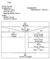
- FIG. 4 illustrates the get_energy subfunction using a structogram.
- step 2.1 START of the get_energy subfunction
- the Brake disc 2 and the thermal energy supplied to the brake pad 3 are determined.
- step 2.2 the kinetic energy of the vehicle 10 is reduced for this purpose between the previous determination time and the current one Determination time determined.
- the friction work in step 2.3 calculated that the brake pad 3 due to the pressing force of the brake cylinder 4th on the brake disc 2.
- the value Y is the coefficient of friction between brake disc and brake shoe.
- BSG is the brake control unit meant the computer that takes over the brake control and in which the Temperature model should run.
- step 2.4 the change in the kinetic energy of the vehicle from the Speed according to step 2.2 with the friction work according to step 2.3 as well compared with a simulated energy BSG and not in more detail here explained adjustment procedures adapted to each other.
- step 2.5 END is finally a value energy_break as a value for the in the Brake disc 2 and energy supplied to the brake pad 3 when braking the Vehicle 10 returned to the main function temp_calc.
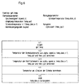
- FIG. 5 illustrates the get_heat_transfer subfunction using a Structogram.
- step 3.2 checks whether the condition speed_n> 0 is fulfilled. If so, what indicating that the vehicle 10 is in motion is carried out in step 3.3 first the heat transfer by forced flow on the Brake shoe side of the brake disc 2 is calculated and then in step 3.5 Heat transfer through forced flow on the cooling surface side of the Brake disc 2 determined. If it is determined in step 3.2 that the condition speed_n> 0 is not fulfilled, which indicates that the vehicle is stationary, is in Step 3.4 the heat transfer through free flow on the brake shoe side and the cooling surface side of the brake disc 2 determined.
- step 3.6 the heat transfer by radiation on the Brake shoe side and / or the cooling surface side of the brake disc 2 determined and in step 3.7 the heat transfer figures for the brake shoe side and the Cooling surface side of brake disc 2 added.
- step 3.8 END the value alpha is returned to the main function temp_calc.
- Figure 6 illustrates the subfunction get_temp using a structogram.
- step 4.4 the temperature at numerous points on the brake disc 2 calculated, in step 4.5 END the calculated temp_disc_n value as the new one Value of the temperature of the brake disc 2 and the brake pad 3 to the Main program temp_calc is returned.
- FIG. 7 illustrates the subfunction speed_max_calc_mo1 using a Structure chart showing a maximum speed speed_max of the vehicle 10 returns that must not be exceeded. It was done in a separate Adaptation step both a maximum limit temperature and a minimum Limit temperature for the brake disc 2 and the brake pad 3 set, namely using a simulation program for different routes and Load conditions.
- step 5.2 it is checked whether the condition temp_disc_n> temp_top is fulfilled is. If this is the case, the value "true" of the variable speed_max in step 5.3 assigned. If the condition temp_disc_n> temp_top is not fulfilled, the The following step 5.4 checks whether the condition temp_disc_n ⁇ temp_bot is satisfied. If this is the case, the variable speed_max is set to "false” assigned as shown in step 5.5. If this is not the case, according to Step 5.6 did nothing. In the last step of the subfunction speed_max_calc_mo1 becomes the value speed_max in step 5.7 END returned. If speed_max has the value "true”, the warning lamp turns 18 put into operation. If the value speed_max has the value "false”, the Warning lamp 18 switched off.
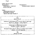
- Figure 8 illustrates the subfunction speed_max_calc_mo2, which is an alternative to Subfunction speed_max_calc_mo1 can be used based on a Structogram.
- the subfunction speed_max_calc_mo2 is preferably used for vehicles 10 used, which are operated as a subway. Such subways are going out accelerated from a stop to a maximum speed and at the slowed down to the next stop.
- step 6.2 the temperature of the brake disc is first cooled 2 and brake pad 3 to the next stop.
- step 6.3 the remaining temperature range up to the specified maximum temperature the brake disc 2 is determined, and in step 6.4 the permissible Maximum speed based on the load pressure and the temperature range certainly.
- step 6.5 END is a permissible maximum speed speed_max is returned to the driver of the vehicle 10 via the display 17 can be displayed.
- the permissible maximum speed speed_max becomes one Temperature model calculated, in which the current temperature of the brake disc 2, the load pressure according to the wheel load sensor 12 and - if available - the upcoming route data for the next section between two stops comes in. So there will be a new maximum speed at each stop calculated the next section of the subway. If the route data of the Path does not exist, then an averaged distance is specified, on the basis of which the maximum speed for the next section of the route is determined.
Landscapes
- Engineering & Computer Science (AREA)
- Mechanical Engineering (AREA)
- General Engineering & Computer Science (AREA)
- Transportation (AREA)
- Valves And Accessory Devices For Braking Systems (AREA)
- Braking Arrangements (AREA)
- Measuring Temperature Or Quantity Of Heat (AREA)
- Regulating Braking Force (AREA)
Applications Claiming Priority (2)
| Application Number | Priority Date | Filing Date | Title |
|---|---|---|---|
| DE19943352 | 1999-09-10 | ||
| DE19943352A DE19943352A1 (de) | 1999-09-10 | 1999-09-10 | Vorrichtung und Verfahren zum Bestimmen der Temperatur an einem Fahrzeug vorgesehenen Bremselementen |
Publications (3)
| Publication Number | Publication Date |
|---|---|
| EP1083360A2 true EP1083360A2 (fr) | 2001-03-14 |
| EP1083360A3 EP1083360A3 (fr) | 2003-03-12 |
| EP1083360B1 EP1083360B1 (fr) | 2006-10-18 |
Family
ID=7921521
Family Applications (1)
| Application Number | Title | Priority Date | Filing Date |
|---|---|---|---|
| EP00118299A Expired - Lifetime EP1083360B1 (fr) | 1999-09-10 | 2000-09-06 | Dispositif et procédé pour déterminer la température d'un élément de frein monté sur un véhicule |
Country Status (3)
| Country | Link |
|---|---|
| EP (1) | EP1083360B1 (fr) |
| AT (1) | ATE343077T1 (fr) |
| DE (2) | DE19943352A1 (fr) |
Cited By (10)
| Publication number | Priority date | Publication date | Assignee | Title |
|---|---|---|---|---|
| ES2169667A1 (es) * | 2000-05-09 | 2002-07-01 | Marin Jose Oliva | Dispositivo de prevencion de la falta de capacidad de frenada. |
| WO2003043864A1 (fr) * | 2001-11-23 | 2003-05-30 | Lucas Automotive Gmbh | Fonctionnement d'un systeme de freinage de vehicule en fonction de la temperature de faces de freinage |
| EP1424256A1 (fr) * | 2002-11-27 | 2004-06-02 | Advics Co., Ltd. | Frein de stationnement électrique |
| WO2005058665A1 (fr) * | 2003-12-04 | 2005-06-30 | Volvo Lastvagnar Ab | Procede permettant d'evaluer le coefficient de frottement entre le stator et le rotor dans un dispositif de freinage |
| EP1950111A2 (fr) | 2007-01-23 | 2008-07-30 | Faiveley Transport Italia S.r.l. | Procédé pour l'évaluation de la température des éléments de freinage d'un véhicule, en particulier un véhicule de voie ferrée |
| WO2013034732A3 (fr) * | 2011-09-09 | 2013-07-04 | Knorr-Bremse Systeme für Schienenfahrzeuge GmbH | Outil de développement de systèmes de freinage pour véhicules ferroviaires |
| WO2015159591A1 (fr) * | 2014-04-15 | 2015-10-22 | Toyota Jidosha Kabushiki Kaisha | Dispositif frein à tambour |
| AT519312A1 (de) * | 2016-09-21 | 2018-05-15 | Siemens Ag Oesterreich | Verfahren zur Beeinflussung eines kinematischen Verhaltens eines Fahrzeugs |
| US10300898B2 (en) | 2017-01-23 | 2019-05-28 | Deere & Company | Cart and implement combination having a brake system |
| US12190657B2 (en) | 2020-03-12 | 2025-01-07 | Volvo Truck Corporation | Method and system for determining that a failure has occurred at or in a wheel end bearing of a vehicle |
Families Citing this family (12)
| Publication number | Priority date | Publication date | Assignee | Title |
|---|---|---|---|---|
| DE10157449B4 (de) * | 2001-11-23 | 2005-07-28 | Lucas Automotive Gmbh | Betrieb eines Fahrzeugbremssystems in Abhängigkeit von Bremsflächentemperaturen |
| DE10233844B4 (de) * | 2002-07-25 | 2007-06-14 | Knorr-Bremse Systeme für Schienenfahrzeuge GmbH | Vorrichtung und Verfahren zur Überwachung des Funktions- und/oder Verschleißzustandes von Bremsbelägen und Bremsscheiben einer Fahrzeugbremse |
| DE10257839B4 (de) * | 2002-12-11 | 2014-12-24 | Robert Bosch Gmbh | Überwachung von Radbremsen |
| DE102005004576B4 (de) * | 2005-02-01 | 2010-10-21 | Fendt, Günter | Bremsanlage mit Überwachungsfunktion für ein Kraftfahrzeug |
| JP4506687B2 (ja) | 2006-02-23 | 2010-07-21 | トヨタ自動車株式会社 | ブレーキ制御装置 |
| GB0802212D0 (en) * | 2008-02-06 | 2008-03-12 | Meritor Heavy Vehicle Braking | A brake system and method |
| FR2936034B1 (fr) * | 2008-09-16 | 2011-07-15 | Valeo Embrayages | Procede d'estimation en temps reel de la temperature des elements d'un dispositif d'embrayage a friction. |
| DE102014116803B4 (de) * | 2014-11-17 | 2025-10-23 | Knorr-Bremse Systeme für Schienenfahrzeuge GmbH | Bremseinrichtung und Verfahren zum gleichmäßigen Abbremsen |
| DE102016214133A1 (de) * | 2016-08-01 | 2018-02-01 | Siemens Aktiengesellschaft | Verfahren zur Ermittlung einer Reibleistung einer Bremsvorrichtung |
| CN119032030A (zh) * | 2022-03-25 | 2024-11-26 | 意大利Itt有限责任公司 | 针对车辆制动元件中的磨损的估计方法 |
| US20260084676A1 (en) * | 2024-09-20 | 2026-03-26 | Ford Global Technologies, Llc | Methods and apparatus to monitor a condition of a braking system |
| FR3166675A1 (fr) * | 2024-09-20 | 2026-03-27 | Renault Sas | Méthode d’estimation de température d’un disque de frein embarqué dans un véhicule |
Citations (1)
| Publication number | Priority date | Publication date | Assignee | Title |
|---|---|---|---|---|
| DE4235364A1 (de) | 1992-10-20 | 1994-04-21 | Knorr Bremse Ag | Verfahren zum Erfassen der Temperatur einer Scheibenbremse |
Family Cites Families (7)
| Publication number | Priority date | Publication date | Assignee | Title |
|---|---|---|---|---|
| DE3407716A1 (de) * | 1984-03-02 | 1985-09-12 | Robert Bosch Gmbh, 7000 Stuttgart | Einrichtung zum messen der staerke von verschleissteilen |
| EP0489887B1 (fr) * | 1990-06-29 | 1995-12-27 | Robert Bosch Gmbh | Vehicule avec surveillance de la temperature des freins |
| DE4316993C2 (de) * | 1993-05-21 | 1995-08-24 | Daimler Benz Ag | Verfahren und Vorrichtung zur Bestimmung des Zustands einer Fahrzeugbremsanlage |
| DE4418768C2 (de) * | 1994-05-28 | 1996-12-12 | Daimler Benz Ag | Verfahren zur Bremsflächentemperaturbestimmung für ein Kraftfahrzeugrad |
| US5731975A (en) * | 1994-08-05 | 1998-03-24 | Toyota Jidosha Kabushiki Kaisha | Temperature assuming apparatus for a brake pad and wheel slip controlling apparatus using the same |
| DE19603193C1 (de) * | 1996-01-31 | 1997-04-03 | Wilke Richard | Motorische, insbesondere elektromotorische, Bremsbetätigungsvorrichtung für Schienenfahrzeuge |
| US5992579A (en) * | 1997-08-07 | 1999-11-30 | Meritor Heavy Vehicle Systems, Llc | Method and apparatus for detecting an improperly adjusted slack adjuster |
-
1999
- 1999-09-10 DE DE19943352A patent/DE19943352A1/de not_active Withdrawn
-
2000
- 2000-09-06 AT AT00118299T patent/ATE343077T1/de not_active IP Right Cessation
- 2000-09-06 EP EP00118299A patent/EP1083360B1/fr not_active Expired - Lifetime
- 2000-09-06 DE DE50013627T patent/DE50013627D1/de not_active Expired - Lifetime
Patent Citations (1)
| Publication number | Priority date | Publication date | Assignee | Title |
|---|---|---|---|---|
| DE4235364A1 (de) | 1992-10-20 | 1994-04-21 | Knorr Bremse Ag | Verfahren zum Erfassen der Temperatur einer Scheibenbremse |
Cited By (15)
| Publication number | Priority date | Publication date | Assignee | Title |
|---|---|---|---|---|
| ES2169667A1 (es) * | 2000-05-09 | 2002-07-01 | Marin Jose Oliva | Dispositivo de prevencion de la falta de capacidad de frenada. |
| US7152935B2 (en) | 2001-11-23 | 2006-12-26 | Lucas Automotive Gmbh | Operation of a vehicle brake system in dependence upon brake surface temperatures |
| WO2003043864A1 (fr) * | 2001-11-23 | 2003-05-30 | Lucas Automotive Gmbh | Fonctionnement d'un systeme de freinage de vehicule en fonction de la temperature de faces de freinage |
| EP1424256A1 (fr) * | 2002-11-27 | 2004-06-02 | Advics Co., Ltd. | Frein de stationnement électrique |
| US7140697B2 (en) | 2002-11-27 | 2006-11-28 | Advics Co., Ltd. | Electric parking brake apparatus |
| US7404316B2 (en) | 2003-12-04 | 2008-07-29 | Volvo Lastvagnar Ab | Method for estimating a measure of the friction coefficient between the stator and the rotor in a braking device |
| WO2005058665A1 (fr) * | 2003-12-04 | 2005-06-30 | Volvo Lastvagnar Ab | Procede permettant d'evaluer le coefficient de frottement entre le stator et le rotor dans un dispositif de freinage |
| EP1950111A2 (fr) | 2007-01-23 | 2008-07-30 | Faiveley Transport Italia S.r.l. | Procédé pour l'évaluation de la température des éléments de freinage d'un véhicule, en particulier un véhicule de voie ferrée |
| WO2013034732A3 (fr) * | 2011-09-09 | 2013-07-04 | Knorr-Bremse Systeme für Schienenfahrzeuge GmbH | Outil de développement de systèmes de freinage pour véhicules ferroviaires |
| WO2015159591A1 (fr) * | 2014-04-15 | 2015-10-22 | Toyota Jidosha Kabushiki Kaisha | Dispositif frein à tambour |
| AT519312A1 (de) * | 2016-09-21 | 2018-05-15 | Siemens Ag Oesterreich | Verfahren zur Beeinflussung eines kinematischen Verhaltens eines Fahrzeugs |
| AT519312B1 (de) * | 2016-09-21 | 2018-09-15 | Siemens Ag Oesterreich | Verfahren zur Beeinflussung eines kinematischen Verhaltens eines Fahrzeugs |
| US11577712B2 (en) | 2016-09-21 | 2023-02-14 | Siemens Mobility Austria Gmbh | Method for influencing the kinematic behavior of a vehicle |
| US10300898B2 (en) | 2017-01-23 | 2019-05-28 | Deere & Company | Cart and implement combination having a brake system |
| US12190657B2 (en) | 2020-03-12 | 2025-01-07 | Volvo Truck Corporation | Method and system for determining that a failure has occurred at or in a wheel end bearing of a vehicle |
Also Published As
| Publication number | Publication date |
|---|---|
| DE50013627D1 (de) | 2006-11-30 |
| DE19943352A1 (de) | 2001-04-05 |
| EP1083360A3 (fr) | 2003-03-12 |
| EP1083360B1 (fr) | 2006-10-18 |
| ATE343077T1 (de) | 2006-11-15 |
Similar Documents
| Publication | Publication Date | Title |
|---|---|---|
| EP1083360B1 (fr) | Dispositif et procédé pour déterminer la température d'un élément de frein monté sur un véhicule | |
| EP3515769B1 (fr) | Procede et appareil pour controler le comportement cinematique 'un vehicule | |
| DE19724092B4 (de) | Verfahren und Vorrichtung zur Ermittlung der Fahrzeugmasse | |
| EP3665048B1 (fr) | Procédé et dispositif pour déterminer des modifications dans le comportement de dynamique longitudinale d'un véhicule ferroviaire | |
| DE102012005068B4 (de) | Verfahren zum Steuern einer eine Reibungsbremse aufweisenden Antriebs- und Bremseinrichtung eines Fahrzeugs | |
| EP4301639B1 (fr) | Procédé et dispositif de surveillance et d'influence de l'état thermique d'un système de frein à friction d'un véhicule ferroviaire | |
| DE10233844B4 (de) | Vorrichtung und Verfahren zur Überwachung des Funktions- und/oder Verschleißzustandes von Bremsbelägen und Bremsscheiben einer Fahrzeugbremse | |
| EP3676139B1 (fr) | Procédé et dispositif de détermination de valeurs réelles d'un véhicule ferroviaire concernant le freinage pour la mise en oeuvre d'un freinage à décélération controlée à capteurs repartis | |
| DE102017004885A1 (de) | Verfahren zur Schätzung der erreichbaren Gesamtbremskräfte zur automatisierten Verzögerung eines Nutzfahrzeugs, Bremsanlage sowie Nutzfahrzeug damit | |
| DE102021104800A1 (de) | Verfahren zur Bestimmung einer optimalen oder maximal zulässigen Geschwindigkeit eines Schienenfahrzeugs | |
| DE102017005816A1 (de) | Verfahren zur Bestimmung der durch Betätigung von Radbremsen erreichbaren Gesamtverzögerungswerten eines Nutzfahrzeugs, Bremsanlage zur Durchführung des Verfahrens sowie Nutzfahrzeug damit | |
| EP0961723B1 (fr) | Procede et systeme de reglage pour l'application de forces d'actionnement definies | |
| DE102021208620A1 (de) | Bestimmung einer, insbesondere möglichen, Verzögerungsgröße | |
| EP1248010B1 (fr) | Dispositif indicateur de la durée de vie d'un disque de frein céramique | |
| DE102021208618B4 (de) | Bestimmung einer möglichen Verzögerungsgröße | |
| DE10040549A1 (de) | Verfahren zur Erfassung der Fahrbahnneigung und Vorrichtung zur Neigungserfassung, insbesondere Neigungssensor | |
| DE102022123152A1 (de) | Verfahren zum Betrieb eines Bremssystems eines Fahrzeugs und Bremssystem | |
| WO2023012192A1 (fr) | Détermination d'une grandeur de décélération, en particulier d'une grandeur de décélération éventuelle | |
| AT522578B1 (de) | Verfahren zur Bestimmung thermischer und mechanischer Zustände von Fahrzeugbremsen | |
| DE102019204687A1 (de) | Bestimmung einer Bremspedalkennlinie für das Bremssystem eines Fahrzeugs mit einer Rekuperations-Bremse | |
| DE102021131927A1 (de) | Verfahren und Einrichtung zur Beeinflussung einer Fahrgeschwindigkeit eines Schienenfahrzeugs | |
| EP4440895A1 (fr) | Procédé et dispositif pour influencer une vitesse de circulation d'un véhicule ferroviaire | |
| EP4570606A1 (fr) | Procédé et dispositif de prédiction d'un niveau de puissance de freinage ou d'une performance de puissance de freinage d'au moins un frein ou un système de freinage d'un véhicule ferroviaire ou d'un ensemble de véhicules ferroviaires | |
| WO2020169737A1 (fr) | Surveillance d'une force de freinage d'un véhicule |
Legal Events
| Date | Code | Title | Description |
|---|---|---|---|
| PUAI | Public reference made under article 153(3) epc to a published international application that has entered the european phase |
Free format text: ORIGINAL CODE: 0009012 |
|
| AK | Designated contracting states |
Kind code of ref document: A2 Designated state(s): AT BE CH CY DE DK ES FI FR GB GR IE IT LI LU MC NL PT SE |
|
| AX | Request for extension of the european patent |
Free format text: AL;LT;LV;MK;RO;SI |
|
| PUAL | Search report despatched |
Free format text: ORIGINAL CODE: 0009013 |
|
| AK | Designated contracting states |
Kind code of ref document: A3 Designated state(s): AT BE CH CY DE DK ES FI FR GB GR IE IT LI LU MC NL PT SE |
|
| AX | Request for extension of the european patent |
Extension state: AL LT LV MK RO SI |
|
| RIC1 | Information provided on ipc code assigned before grant |
Ipc: 7B 60T 8/00 B Ipc: 7F 16D 66/00 A Ipc: 7B 60T 17/22 B |
|
| 17P | Request for examination filed |
Effective date: 20030912 |
|
| AKX | Designation fees paid |
Designated state(s): AT BE CH CY DE DK ES FI FR GB GR IE IT LI LU MC NL PT SE |
|
| 17Q | First examination report despatched |
Effective date: 20031117 |
|
| GRAP | Despatch of communication of intention to grant a patent |
Free format text: ORIGINAL CODE: EPIDOSNIGR1 |
|
| GRAS | Grant fee paid |
Free format text: ORIGINAL CODE: EPIDOSNIGR3 |
|
| GRAA | (expected) grant |
Free format text: ORIGINAL CODE: 0009210 |
|
| AK | Designated contracting states |
Kind code of ref document: B1 Designated state(s): AT BE CH CY DE DK ES FI FR GB GR IE IT LI LU MC NL PT SE |
|
| PG25 | Lapsed in a contracting state [announced via postgrant information from national office to epo] |
Ref country code: NL Free format text: LAPSE BECAUSE OF FAILURE TO SUBMIT A TRANSLATION OF THE DESCRIPTION OR TO PAY THE FEE WITHIN THE PRESCRIBED TIME-LIMIT Effective date: 20061018 Ref country code: FI Free format text: LAPSE BECAUSE OF FAILURE TO SUBMIT A TRANSLATION OF THE DESCRIPTION OR TO PAY THE FEE WITHIN THE PRESCRIBED TIME-LIMIT Effective date: 20061018 Ref country code: IE Free format text: LAPSE BECAUSE OF FAILURE TO SUBMIT A TRANSLATION OF THE DESCRIPTION OR TO PAY THE FEE WITHIN THE PRESCRIBED TIME-LIMIT Effective date: 20061018 |
|
| REG | Reference to a national code |
Ref country code: GB Ref legal event code: FG4D Free format text: NOT ENGLISH |
|
| REG | Reference to a national code |
Ref country code: CH Ref legal event code: EP Ref country code: IE Ref legal event code: FG4D Free format text: LANGUAGE OF EP DOCUMENT: GERMAN |
|
| REF | Corresponds to: |
Ref document number: 50013627 Country of ref document: DE Date of ref document: 20061130 Kind code of ref document: P |
|
| GBT | Gb: translation of ep patent filed (gb section 77(6)(a)/1977) |
Effective date: 20061129 |
|
| PG25 | Lapsed in a contracting state [announced via postgrant information from national office to epo] |
Ref country code: DK Free format text: LAPSE BECAUSE OF FAILURE TO SUBMIT A TRANSLATION OF THE DESCRIPTION OR TO PAY THE FEE WITHIN THE PRESCRIBED TIME-LIMIT Effective date: 20070118 Ref country code: SE Free format text: LAPSE BECAUSE OF FAILURE TO SUBMIT A TRANSLATION OF THE DESCRIPTION OR TO PAY THE FEE WITHIN THE PRESCRIBED TIME-LIMIT Effective date: 20070118 |
|
| PG25 | Lapsed in a contracting state [announced via postgrant information from national office to epo] |
Ref country code: ES Free format text: LAPSE BECAUSE OF FAILURE TO SUBMIT A TRANSLATION OF THE DESCRIPTION OR TO PAY THE FEE WITHIN THE PRESCRIBED TIME-LIMIT Effective date: 20070129 |
|
| PG25 | Lapsed in a contracting state [announced via postgrant information from national office to epo] |
Ref country code: PT Free format text: LAPSE BECAUSE OF FAILURE TO SUBMIT A TRANSLATION OF THE DESCRIPTION OR TO PAY THE FEE WITHIN THE PRESCRIBED TIME-LIMIT Effective date: 20070319 |
|
| NLV1 | Nl: lapsed or annulled due to failure to fulfill the requirements of art. 29p and 29m of the patents act | ||
| ET | Fr: translation filed | ||
| REG | Reference to a national code |
Ref country code: IE Ref legal event code: FD4D |
|
| PLBE | No opposition filed within time limit |
Free format text: ORIGINAL CODE: 0009261 |
|
| STAA | Information on the status of an ep patent application or granted ep patent |
Free format text: STATUS: NO OPPOSITION FILED WITHIN TIME LIMIT |
|
| 26N | No opposition filed |
Effective date: 20070719 |
|
| BERE | Be: lapsed |
Owner name: KNORR-BREMSE SYSTEME FUR SCHIENENFAHRZEUGE G.M.B. Effective date: 20070930 |
|
| PG25 | Lapsed in a contracting state [announced via postgrant information from national office to epo] |
Ref country code: MC Free format text: LAPSE BECAUSE OF NON-PAYMENT OF DUE FEES Effective date: 20070930 Ref country code: GR Free format text: LAPSE BECAUSE OF FAILURE TO SUBMIT A TRANSLATION OF THE DESCRIPTION OR TO PAY THE FEE WITHIN THE PRESCRIBED TIME-LIMIT Effective date: 20070119 |
|
| REG | Reference to a national code |
Ref country code: CH Ref legal event code: PL |
|
| PG25 | Lapsed in a contracting state [announced via postgrant information from national office to epo] |
Ref country code: CH Free format text: LAPSE BECAUSE OF NON-PAYMENT OF DUE FEES Effective date: 20070930 Ref country code: LI Free format text: LAPSE BECAUSE OF NON-PAYMENT OF DUE FEES Effective date: 20070930 |
|
| PG25 | Lapsed in a contracting state [announced via postgrant information from national office to epo] |
Ref country code: BE Free format text: LAPSE BECAUSE OF NON-PAYMENT OF DUE FEES Effective date: 20070930 |
|
| PG25 | Lapsed in a contracting state [announced via postgrant information from national office to epo] |
Ref country code: AT Free format text: LAPSE BECAUSE OF NON-PAYMENT OF DUE FEES Effective date: 20070906 |
|
| PG25 | Lapsed in a contracting state [announced via postgrant information from national office to epo] |
Ref country code: CY Free format text: LAPSE BECAUSE OF FAILURE TO SUBMIT A TRANSLATION OF THE DESCRIPTION OR TO PAY THE FEE WITHIN THE PRESCRIBED TIME-LIMIT Effective date: 20061018 Ref country code: LU Free format text: LAPSE BECAUSE OF NON-PAYMENT OF DUE FEES Effective date: 20070906 |
|
| REG | Reference to a national code |
Ref country code: FR Ref legal event code: PLFP Year of fee payment: 16 |
|
| PGFP | Annual fee paid to national office [announced via postgrant information from national office to epo] |
Ref country code: GB Payment date: 20150922 Year of fee payment: 16 Ref country code: DE Payment date: 20150923 Year of fee payment: 16 |
|
| PGFP | Annual fee paid to national office [announced via postgrant information from national office to epo] |
Ref country code: FR Payment date: 20150923 Year of fee payment: 16 |
|
| PGFP | Annual fee paid to national office [announced via postgrant information from national office to epo] |
Ref country code: IT Payment date: 20150925 Year of fee payment: 16 |
|
| REG | Reference to a national code |
Ref country code: DE Ref legal event code: R119 Ref document number: 50013627 Country of ref document: DE |
|
| GBPC | Gb: european patent ceased through non-payment of renewal fee |
Effective date: 20160906 |
|
| REG | Reference to a national code |
Ref country code: FR Ref legal event code: ST Effective date: 20170531 |
|
| PG25 | Lapsed in a contracting state [announced via postgrant information from national office to epo] |
Ref country code: DE Free format text: LAPSE BECAUSE OF NON-PAYMENT OF DUE FEES Effective date: 20170401 Ref country code: FR Free format text: LAPSE BECAUSE OF NON-PAYMENT OF DUE FEES Effective date: 20160930 Ref country code: GB Free format text: LAPSE BECAUSE OF NON-PAYMENT OF DUE FEES Effective date: 20160906 |
|
| PG25 | Lapsed in a contracting state [announced via postgrant information from national office to epo] |
Ref country code: IT Free format text: LAPSE BECAUSE OF NON-PAYMENT OF DUE FEES Effective date: 20160906 |