EP1083365A1 - Courroie crantee, dispositif de transmission a courroie crantee et machines de bureau - Google Patents
Courroie crantee, dispositif de transmission a courroie crantee et machines de bureau Download PDFInfo
- Publication number
- EP1083365A1 EP1083365A1 EP00911327A EP00911327A EP1083365A1 EP 1083365 A1 EP1083365 A1 EP 1083365A1 EP 00911327 A EP00911327 A EP 00911327A EP 00911327 A EP00911327 A EP 00911327A EP 1083365 A1 EP1083365 A1 EP 1083365A1
- Authority
- EP
- European Patent Office
- Prior art keywords
- tooth
- belt
- pulley
- portions
- tooth groove
- Prior art date
- Legal status (The legal status is an assumption and is not a legal conclusion. Google has not performed a legal analysis and makes no representation as to the accuracy of the status listed.)
- Withdrawn
Links
Images







Classifications
-
- B—PERFORMING OPERATIONS; TRANSPORTING
- B41—PRINTING; LINING MACHINES; TYPEWRITERS; STAMPS
- B41J—TYPEWRITERS; SELECTIVE PRINTING MECHANISMS, i.e. MECHANISMS PRINTING OTHERWISE THAN FROM A FORME; CORRECTION OF TYPOGRAPHICAL ERRORS
- B41J19/00—Character- or line-spacing mechanisms
- B41J19/005—Cable or belt constructions for driving print, type or paper-carriages, e.g. attachment, tensioning means
-
- B—PERFORMING OPERATIONS; TRANSPORTING
- B41—PRINTING; LINING MACHINES; TYPEWRITERS; STAMPS
- B41J—TYPEWRITERS; SELECTIVE PRINTING MECHANISMS, i.e. MECHANISMS PRINTING OTHERWISE THAN FROM A FORME; CORRECTION OF TYPOGRAPHICAL ERRORS
- B41J19/00—Character- or line-spacing mechanisms
- B41J19/18—Character-spacing or back-spacing mechanisms; Carriage return or release devices therefor
- B41J19/20—Positive-feed character-spacing mechanisms
-
- F—MECHANICAL ENGINEERING; LIGHTING; HEATING; WEAPONS; BLASTING
- F16—ENGINEERING ELEMENTS AND UNITS; GENERAL MEASURES FOR PRODUCING AND MAINTAINING EFFECTIVE FUNCTIONING OF MACHINES OR INSTALLATIONS; THERMAL INSULATION IN GENERAL
- F16G—BELTS, CABLES, OR ROPES, PREDOMINANTLY USED FOR DRIVING PURPOSES; CHAINS; FITTINGS PREDOMINANTLY USED THEREFOR
- F16G1/00—Driving-belts
- F16G1/28—Driving-belts with a contact surface of special shape, e.g. toothed
-
- F—MECHANICAL ENGINEERING; LIGHTING; HEATING; WEAPONS; BLASTING
- F16—ENGINEERING ELEMENTS AND UNITS; GENERAL MEASURES FOR PRODUCING AND MAINTAINING EFFECTIVE FUNCTIONING OF MACHINES OR INSTALLATIONS; THERMAL INSULATION IN GENERAL
- F16H—GEARING
- F16H7/00—Gearings for conveying rotary motion by endless flexible members
- F16H7/02—Gearings for conveying rotary motion by endless flexible members with belts; with V-belts
- F16H7/023—Gearings for conveying rotary motion by endless flexible members with belts; with V-belts with belts having a toothed contact surface or regularly spaced bosses or hollows for slipless or nearly slipless meshing with complementary profiled contact surface of a pulley
Definitions
- the present invention relates to a toothed belt, to a toothed belt power transmission apparatus, and to business equipment using such a toothed belt power transmission apparatus.
- the present invention belongs particularly to the technical field of reducing the nonuniformity of belt velocity, i.e., the variation in belt velocity.
- Such a type of toothed belt has been known in the art.
- toothed belts having belt teeth of trapezoidal profile were used.
- belts with a tooth profile having flank surfaces of convex profile have been proposed.
- Such a type of belt has now been used extensively nowadays.
- One of such tooth profiles is shown in Japanese Unexamined Patent Application Gazette No. S50-42252, which is known in the art as the STPD tooth profile.
- the other tooth profile is shown in Japanese Unexamined Patent Application Gazette No. S59-89852, which is known in the art as the HTD-II tooth profile.
- the former tooth profile i.e., the STPD tooth profile
- the latter tooth profile i.e., the HTD-II tooth profile
- the latter tooth profile has been also put to practical use (for example, POWER GRIP GT BELT, a product of UNITTA COMPANY).
- Japanese Unexamined Patent Application Gazette No. S64-74341 shows and proposes a toothed belt for the purpose of accurate location drive of movable parts incorporated in a business machine. More specifically, as shown in Figure 17 , a plurality of belt tooth portions 11' , 11' , ... (only one of which is shown in the figure) are provided along a land line LL of a main body 9 ' of a belt 8 ' at their fixed pitch.
- Each belt tooth portion 11 ' comprises tooth root portions 12 ' formed of circularly arcuate surfaces which are arranged symmetrically with each other in respect to a centerline C2 in the tooth width direction, power transmission portions 13 ', 13 ' formed of circularly arcuate surfaces of convex profile which contiguously adjoin the tooth root portions 12 ', 12 ' and are arranged symmetrically with each other in respect to the tooth width direction centerline C2, and tooth tip portions 14 ', 14 ' formed of circularly arcuate surfaces which contiguously adjoin the power transmission portions 13 ', 13 ' and are arranged symmetrically with each other in respect to the tooth width direction centerline C2, wherein these tooth tip portions 14 ', 14 ' are interconnected by a tooth crest surface 15' formed of a flat surface.
- the tooth root portion 12 ' of each of the belt tooth portions 11 ' substantially comes into contact with a tooth top arc portion 4 ' of a pulley tooth groove portion 3 '.
- the backlash of the belt tooth portion 11 ' at the pulley tooth groove portion 3 ' gradually increases from the tooth root portion to the tooth tip portion of the belt tooth portion 11 ' and the depth of the pulley tooth groove portion 3 ' exceeds the height of the belt tooth portion 11 '.
- the backlash with the pulley tooth groove portion 3 ' is reduced to zero at the tooth root portion 12 ' of the belt tooth portion 11 ', while the backlash with the pulley tooth groove portion 3 ' is gradually increased from the tooth root portion to the tooth tip portion of the belt tooth portion 11 ' so that the belt tooth portion 11' tapers toward the tooth tip portion, thereby to suppress meshing interference between the belt tooth portion 11' and the tooth top arc portion 4 ' of the pulley tooth groove portion 3 ' for the reduction of belt pitch line variation due to such meshing interference.
- tooth groove flank surface portions of concave profile of the pulley tooth groove portion 3 ' are assigned the reference numeral 5 '
- a tooth groove bottom portion is assigned the reference numeral 6 '
- the pitch line of the belt 8 ' is denoted by PL, which corresponds to the pitch circle of the pulley 1 '.
- the outer peripheral portion of the pulley 1 ' is shown in expanded fashion, together with the belt 8 '.
- a character printing (including printing of images) device making utilization of a toothed belt power transmission apparatus is used widely.
- a carriage carrying thereon an ink supply and a printing mechanism such as a hammer is attached to a toothed belt.
- the toothed belt is wound around toothed pulleys and the pulleys are forwarded and reversed to cause the carriage to reciprocate.
- the nonuniformity of velocity of the toothed belt when traveling over the pulleys i.e., the belt velocity variation
- the meshing vibration (velocity nonuniformity caused by meshing) of toothed belt may cause printing nonuniformity and image nonuniformity, so that there have been strong demands for the reduction of the nonuniformity of belt velocity caused by meshing.
- a toothed belt such as an STPD toothed belt or HTD-II toothed belt, wherein the tooth pitch is set below 3 mm (for example, either 3 mm, 2 mm, or 1.5 mm), and the tooth has a profile which is just a scaledown of the tooth profile of relatively large tooth pitch such as 8-mm pitch or 5-mm pitch.
- an object of the present invention is to reduce the nonuniformity of toothed belt velocity as low as possible.
- the inventor conducted research.
- the research result bad shown that, for the case of toothed belts having tooth portions with convex flank surface portions, the flank maximum pressure angle had considerable influence on the nonuniformity of velocity. This factor had not at all been taken into consideration before. That is to say, in conventional toothed belts having either an STPD tooth profile or an HTD-II tooth profile for use in high power transmission applications, the maximum pressure angle of the tooth flank surface is set low for the avoidance of tooth jumping occurring during high power transmission operation.
- the flank maximum pressure angle is set to fall in the range between an angle of 14.2 degrees and an angle of 14.4 degrees
- the flank maximum pressure angle is set to fall in the range between an angle of 7.5 degrees and an angle of 8.1 degrees.
- the flank maximum pressure angle is set to fall in the range between an angle of 15 degrees and an angle of 25 degrees.
- the present invention provides a toothed belt which comprises a belt main body with a pitch line on which a tensile member is embedded therein and a plurality of belt tooth portions provided at a fixed pitch on a land line of the belt main body.
- Each of the belt tooth portions comprises tooth root portions formed of circularly arcuate surfaces which are arranged symmetrically with each other in respect to a centerline in the tooth width direction, power transmission portions formed of circularly arcuate surfaces of convex profile which contiguously adjoin the tooth root portions, lie at flank surfaces of the tooth portion, and are arranged symmetrically with each other in respect to the tooth width direction centerline, tooth tip portions formed of circularly arcuate surfaces which contiguously adjoin the power transmission portions and are arranged symmetrically with each other in respect to the tooth width direction centerline, and a tooth crest surface formed of an approximately flat surface which interconnects the tooth tip portions, wherein the maximum pressure angle at where the power transmission portion of the belt tooth flank surface and the tooth root portion are connected together is between an angle of 15 degrees and an angle of 25 degrees.
- the belt pitch line moves vertically in a direction normal to the belt span, resulting in the occurrence of meshing velocity nonuniformity.
- the amount of vertical movement of the belt pitch line is determined by a reaction force produced when the belt tooth portion slides into the pulley tooth groove portion and a component of a belt tension force produced when the belt is pushed upward by the reaction force. Because of this, as the contact position moves away from the perfect meshing position of the belt tooth portion and the pulley tooth groove portion, the belt tension force component decreases, thereby increasing the amount of upward movement of the belt pitch line. In other words, earlier contacting of the belt tooth portion with the pulley tooth groove portion results in greater velocity nonuniformity.
- the maximum pressure angle cannot be increased excessively and if the maximum pressure angle is too great, this will not reduce the nonuniformity of velocity; rather the nonuniformity of velocity increases. That is to say, as described above, the amount of shift of the belt span is determined by reaction force (produced when the belt tooth portion slides into the pulley tooth groove portion after their flank surfaces come into contact with each other) and belt tension force component. However, at that time, if the maximum pressure angle is too great, then a component of a reaction force in the vertical direction (i.e., in the direction normal to the belt span) produced when the belt tooth portion slides into the pulley tooth groove portion becomes too great. This will not allow the belt tooth portion to smoothly slide into the pulley tooth groove portion, therefore pushing up the belt pitch line to increase the nonuniformity of velocity.
- the analysis result obtained by the inventor shows that an optimal allowable range for the maximum pressure angle is between an angle of 15 degrees and an angle of 25 degrees as described above.
- the present invention is able to reduce the nonuniformity of velocity more effectively.
- the maximum pressure angle at where the power transmission portion of the belt tooth flank surface and the tooth root portion are connected together is between an angle of 16 degrees and an angle of 23 degrees. Furthermore, the maximum pressure angle is between an angle of 17 degrees and an angle of 22 degrees. As a result of such arrangement, the nonuniformity of velocity can be reduced to a further extent.
- the present invention provides a toothed belt comprising a belt main body with a pitch line on which a tensile member is embedded therein and a plurality of belt tooth portions provided at a fixed pitch on a land line of the belt main body.
- Each of the belt tooth portions comprises tooth root portions formed of circularly arcuate surfaces which are arranged symmetrically with each other in respect to a centerline in the tooth width direction, power transmission portions formed of circularly arcuate surfaces of convex profile which contiguously adjoin the tooth root portions, lie at flank surfaces of the tooth portion, and are arranged symmetrically with each other in respect to the tooth width direction centerline, and a tooth tip end portion formed of a circularly arcuate surface which is so provided as to interconnect the power transmission portions and whose center point lies on the tooth width direction centerline, wherein the maximum pressure angle at where the power transmission portion of the belt tooth flank surface and the tooth root portion are connected together is between an angle of 15 degrees and an angle of 25 degrees.
- Such a tooth construction is able to provide the same effects as above. Further, since the tooth tip end portion of the belt tooth portion is defined by a single circularly arcuate surface, this makes it possible to further delay the contacting of the belt tooth portion with the pulley tooth groove portion in comparison with increasing only the maximum pressure angle (see the virtual line of Figure 8) . Accordingly, the nonuniformity of belt velocity can be reduced to a further extent.
- the maximum pressure angle in the toothed belt is between an angle of 16 degrees and an angle of 23 degrees. Further, the maximum pressure angle is between an angle of 17 degrees and an angle of 22 degrees. As a result of such setting, the nonuniformity of velocity of the toothed belt can be reduced to a further extent.
- the present invention provides a toothed belt power transmission apparatus comprising a combination of any one of the preceding toothed belts and toothed pulleys each having a plurality of pulley tooth groove portions which are provided at a fixed pitch on a pulley outside diameter line.
- Each of the pulley tooth groove portions comprises tooth top arc portions formed of circularly arcuate surfaces which are arranged symmetrically with each other in respect to a centerline in the tooth groove width direction, tooth groove flank surface portions formed of circularly arcuate surfaces of concave profile which contiguously adjoin the tooth top arc portions and are arranged symmetrically with each other in respect to the tooth groove width direction centerline, and a tooth groove bottom portion provided so as to interconnect the tooth groove flank surface portions.
- the belt tooth portion has flank surfaces whose profile is substantially the same as that of flank surfaces of the pulley tooth groove portion. Further, in a power transmission state (i.e., in a working state) in which the toothed belt is wound around the toothed pulleys and a tension force is applied to the toothed belt, the pressure angles of the belt tooth portion flank surface and the pulley tooth groove portion flank surface at their respective locations in the tooth height direction are made approximately equal to each other and a belt land portion comes into contact with a pulley outside diameter portion.
- the inventor's research shows that if the maximum pressure angle of the pulley tooth groove portion is set smaller than the maximum pressure angle of the belt tooth portion, this increases the nonuniformity of velocity of the belt. That is to say, when the maximum pressure angle of the pulley tooth groove portion is set smaller than the maximum pressure angle of the belt tooth portion, this certainly delays the contacting of the belt tooth flank surface with the pulley tooth groove flank surface; however, the belt tooth flank surface is brought into contact, not with the pulley tooth groove flank surface but with the tooth top arc portion (see Figure 5(b) ).
- the toothed belt power transmission apparatus of the present invention it is arranged such that the pressure angles of the belt tooth portion flank surface and the pulley tooth groove portion flank surface at their respective locations in the tooth height direction are made approximately equal to each other, so that the belt tooth flank surface comes into uniform contact with the pulley tooth groove flank surface.
- This allows the belt tooth portion to smoothly slide into the pulley tooth groove portion (see Figure 5(a) ).
- the belt pitch line will not be pushed up, which considerably reduces the nonuniformity of velocity of the belt.
- the pulley tooth groove portion of the toothed pulley has a tooth groove bottom portion which is formed of an approximately flat surface.
- the tooth groove bottom portion of the pulley tooth groove portion and the tooth crest surface of the belt tooth portion are formed of identical, approximately flat surfaces, which is preferable.
- the tooth groove bottom portion may be formed of a surface inscribing an arc of a circle having its center in the pulley central direction.
- the present invention provides a toothed belt power transmission apparatus comprising a combination of the foregoing toothed belt and toothed pulleys each having a plurality of pulley tooth groove portions which are provided at a fixed pitch on a pulley outside diameter line.
- Each of the pulley tooth groove portions comprises tooth top arc portions formed of circularly arcuate surfaces which are arranged symmetrically with each other in respect to a centerline in the tooth groove width direction, tooth groove flank surface portions formed of circularly arcuate surfaces of concave profile which contiguously adjoin the tooth top arc portions and are arranged symmetrically with each other in respect to the tooth groove width direction centerline, and a tooth groove bottom portion provided so as to interconnect the tooth groove flank surface portions, wherein the belt tooth portion has flank surfaces whose profile is substantially the same as that of flank surfaces of the pulley tooth groove portion and wherein in a power transmission state in which the toothed belt is wound around the toothed pulleys and a tension force is applied to the toothed belt, the pressure angles of the belt tooth portion flank surface and the pulley tooth groove portion flank surface at their respective locations in the tooth height direction are made approximately equal to each other and a belt land portion comes into contact with a pulley outside diameter portion.
- This construction is also able to provide the
- the pulley tooth groove portion of each of the toothed pulleys has a tooth groove bottom portion which comprises a circularly arcuate surface inscribing an arc of a circle whose center point lies on the tooth groove width direction centerline and whose radius is greater than that of the tooth tip end portion of the belt tooth portion. That is to say, in the case the belt tooth portion has a tooth tip end portion which is a circularly arcuate surface (i.e., a curvilinear surface inscribing the arc of a circle), the pulley tooth groove portion may have a tooth groove bottom portion which is an approximately flat surface.
- the tooth groove bottom portion of the pulley tooth groove portion is formed of a circularly arcuate surface whose radius is greater than that of the tooth tip end portion of the belt tooth portion. This arrangement is preferable because the belt tooth portion is able to slide into the pulley tooth groove portion in a much smoother manner.
- the present invention provides a toothed belt power transmission apparatus comprising a combination of a toothed belt and toothed pulleys.
- the toothed belt has a belt main body with a pitch line on which a tensile member is embedded therein, a plurality of belt tooth portions provided at a fixed pitch in the belt main body, and a land portion provided between adjacent belt tooth portions.
- Each of the belt tooth portions has power transmission portions formed of circularly arcuate surfaces of convex profile which lie at flank surfaces of the tooth portion and are arranged symmetrically with each other in respect to a centerline in the tooth width direction, tooth tip portions formed of circularly arcuate surfaces which contiguously adjoin the power transmission portions and are arranged symmetrically with each other in respect to the tooth width direction centerline, and a tooth crest surface formed of an approximately flat surface which is so provided as to interconnect the tooth tip portions.
- each of the toothed pulleys has a plurality of pulley tooth groove portions provided at a fixed pitch on a pulley outside diameter line.
- Each of the pulley tooth groove portions has tooth top arc portions formed of circularly arcuate surfaces which are arranged symmetrically with each other in respect to a centerline in the tooth groove width direction, tooth groove flank surface portions formed of circularly arcuate surfaces of concave profile which contiguously adjoin the tooth top arc portions and are arranged symmetrically with each other in respect to the tooth groove width direction centerline, and a tooth groove bottom portion provided so as to interconnect the tooth groove flank surface portions.
- the maximum pressure angle at where the tooth top arc portion and the tooth groove flank surface portion in the pulley tooth groove portion are connected together is between an angle of 15 degrees and an angle of 25 degrees and the belt tooth portion has flank surfaces whose profile is substantially the same as that of flank surfaces of the pulley tooth groove portion.
- the pressure angles of the belt tooth portion flank surface and the pulley tooth groove portion flank surface at their respective locations in the tooth height direction are made approximately equal to each other and a belt land portion does not come into contact with a pulley outside diameter portion.
- the arrangement for reducing the nonuniformity of belt velocity by increasing the maximum pressure angle is effective for toothed belt power transmission apparatus that are used in such a condition that the belt land portion does not come into contact with a pulley outside diameter portion.
- areas of the belt land portion, the tooth root portion of the tooth portion, and the tooth flank surface that lie outside beyond the pulley outside diameter portion in the radial direction have no direct influence on the behaviors of the belt tooth portion at the time of meshing.
- the maximum pressure angle of the belt tooth portion in the belt alone is not important, but the maximum pressure angle at a connection point of the tooth top arc portion and the tooth groove flank surface portion is important.
- the maximum pressure angle at where the tooth top arc portion and the tooth groove flank surface portion are connected together is between an angle of 15 degrees and an angle of 25 degrees, as a result of which arrangement the same operation and effects as the above can be obtained.
- the land portion of the toothed belt comprises an approximately flat surfaces which is interconnected with the belt tooth portion flank surfaces through tooth root portions formed of circularly arcuate surfaces which are arranged symmetrically with the tooth width direction centerline.
- the land portion of the belt since there is no constraint when taking into account the nonuniformity of belt velocity, may be formed of a circularly arcuate surface; however, it is preferable that the belt land portion be formed of an approximately flat surface. That is to say, toothed belts made of polyurethane have been used widely in equipment for business use because they are superior in the shape accuracy of tooth portions or the like. Particularly, when the belt tooth portion pitch is below 1.5 mm, nearly all of toothed belts are made of polyurethane, for rubber belts are not able to meet requirements of the business equipment because they are poor in tooth shape accuracy.
- a concave portion is practically provided in the belt land portion in order to separate the core cord from the land line.
- the belt tooth portion pitch is below 1.5 mm
- the formation dimensions of such a concave portion are considerably small, resulting in difficult die processing.
- the core cord is provided directly over the land line without the provision of the foregoing concave portion, and the belt is used in such a condition that the belt land portion is not brought into contact with a pulley outside diameter portion so as to prevent the core cord from being damaged by contact with the pulley outside diameter portion.
- the belt land portion is an approximately flat surface, the position of the core cord can be made stable by the belt land portion which is approximately flat.
- the maximum pressure angle at where the tooth top arc portion and the tooth groove flank surface portion in the pulley tooth groove portion of the toothed belt power transmission apparatus are connected together is between an angle of 16 degrees and an angle of 23 degrees. Further, the maximum pressure angle is between an angle of 17 degrees and an angle of 22 degrees. As a result of such arrangement, the nonuniformity of toothed belt velocity can be reduced to a further extent.
- the pulley tooth groove portion of the toothed pulley has a tooth groove bottom portion which is formed of an approximately flat surface.
- the present invention provides a toothed belt power transmission apparatus comprising a combination of a toothed belt and toothed pulleys.
- the toothed belt has a belt main body with a pitch line on which a tensile member is embedded therein, a plurality of belt tooth portions provided at a fixed pitch in the belt main body, and a land portion provided between adjacent belt tooth portions.
- Each of the belt tooth portions has power transmission portions formed of circularly arcuate surfaces of convex profile which lie at flank surfaces of the tooth portion and are arranged symmetrically with each other in respect to a centerline in the tooth width direction and a tooth tip end portion formed of a circularly arcuate surface which is so provided as to interconnect the power transmission portions and whose center point lies on the tooth width direction centerline.
- each of the toothed pulleys has a plurality of pulley tooth groove portions provided at a fixed pitch on a pulley outside diameter line.
- Each of the pulley tooth groove portions has tooth top arc portions formed of circularly arcuate surfaces which are arranged symmetrically with each other in respect to a centerline in the tooth groove width direction, tooth groove flank surface portions formed of circularly arcuate surfaces of concave profile which contiguously adjoin the tooth top arc portions and are arranged symmetrically with each other in respect to the tooth groove width direction centerline, and a tooth groove bottom portion provided so as to interconnect the tooth groove flank surface portions.
- the maximum pressure angle at where the tooth top arc portion and the tooth groove flank surface portion in the pulley tooth groove portion are connected together is between an angle of 15 degrees and an angle of 25 degrees.
- the belt tooth portion has flank surfaces whose profile is substantially the same as that of flank surfaces of the pulley tooth groove portion.
- the pressure angles of the belt tooth portion flank surface and the pulley tooth groove portion flank surface at their respective locations in the tooth height direction are made approximately equal to each other and a belt land portion does not come into contact with a pulley outside diameter portion.
- the construction of the belt tooth portion is changed to the same one as the above and the same operation and effects as the above can be obtained.
- the land portion of the toothed belt in the toothed belt power transmission apparatus comprises an approximately flat surface which is interconnected with the belt tooth portion flank surfaces through tooth root portions formed of circularly arcuate surfaces which are arranged symmetrically with the tooth width direction centerline.
- the maximum pressure angle at where the tooth top arc portion and the tooth groove flank surface portion in the pulley tooth groove portion are connected together is between an angle of 16 degrees and an angle of 23 degrees. Moreover, the maximum pressure angle is between an angle of 17 degrees and an angle of 22 degrees. As a result of such arrangement, the nonuniformity of toothed belt velocity can be reduced to a further extent.
- the pulley tooth groove portion of the toothed pulley has a tooth groove bottom portion which comprises a circularly arcuate surface inscribing an arc of a circle whose center point lies on the tooth groove width direction centerline and whose radius is greater than that of the tooth tip end portion of the belt tooth portion.
- the present invention provides equipment for use in business applications which is provided with a toothed belt power transmission apparatus formed in accordance with the present invention wherein a carriage is attached to the toothed belt.
- FIG. 3 there is shown the entire structure of a toothed belt power transmission apparatus A according to a first embodiment of the present invention.
- the power transmission apparatus A is of the type that is mounted in business equipment such as printers or photocopiers.
- the reference numeral 1 denotes a driving pulley formed of a toothed pulley
- the reference numeral 2 denotes a driven pulley formed of a toothed pulley.
- These pulleys 1 and 2 are so arranged as to opposite to each other in horizontal direction.
- a toothed belt 8 is wound around both the pulleys 1 and 2 , being in meshing engagement therewith.
- a carriage 19 carrying a supply of ink and a printing mechanisms such a hammer is fixedly attached, at its attachment portion 19a , to a lower span of the toothed belt 8 so as to be movable together with the toothed belt 8 .
- the pulleys 1 and 2 are forwarded and reversed to cause the toothed belt 8 to travel, so that the carriage 19 reciprocates between the driving pulley 1 and the driven pulley 2 .
- the driving and driven pulleys 1 and 2 each have a plurality of pulley tooth grooves 3 , 3 , ... (only one of which is shown in the figure) which are uniformly spaced apart by a fixed pitch on an outside diameter line of the pulley outer periphery.
- Each pulley tooth groove portion 3 has (a) a pair of tooth top arc portions 4, 4 formed of curvilinear surfaces each inscribing an arc of a circle (i.e., circularly arcuate surfaces) having a radius r1P which are arranged symmetrically with each other in respect to its centerline C1 in the tooth groove width direction, (b) a pair of tooth groove flank surface portions 5, 5 formed of circularly arcuate surfaces of concave profile having a center point O1P in the vicinity of a pitch circle PC (i.e., the same point as the circularly arcuate surface center point O1B of a power transmission portion 13 in a tooth portion 11 of the toothed belt 8 which is brought into meshing engagement with the pulleys 1 and 2 as described later) and a radius RP greater than the tooth width W of the toothed belt 8 which contiguously adjoin the tooth top arc portions 4, 4 and are arranged symmetrically with each other in respect to the tooth groove width direction centerline C1, and (c
- the toothed belt 8 has a belt main body 9 made of elastic material. It is preferable that the belt main body 9 be made of either rubber or polyurethane. Other than these materials, the belt main body 9 may be formed of, for example, synthetic resin material. As rubber material for the belt main body 9 , chloroprene rubber is used. Other than chloroprene rubber, either NBR, SBR, EPDM, or the like may be useful. These rubber materials preferably have a JIS-A hardness between about 65 degrees to about 85 degrees. Thermohardening ether polyurethane may be used as a material to form the belt main body 9 . Thermoplastic ester polyurethane may be used also as a material to form the belt main body 9 .
- Thermohardening ether polyurethane may be used as a material to form the belt main body 9 .
- Thermoplastic ester polyurethane may be used also as a material to form the belt main body 9 .
- a core cord embedded in the belt main body 9 on a pitch line PL thereof is a core cord (not shown in the figure) that serves as a tensile member.
- the core cord is usually formed of glass fiber or aramid fiber, regardless of which one of rubber or polyurethane is used to form the belt main body 9 .
- the core cord may be made of carbon fiber or PBO fiber.
- a plurality of tooth portions 11, 11 , ... (only one of which is shown in the figure) having a tooth wide W are provided on a land line LL of the belt main body 9 in the direction of the belt length at a fixed pitch.
- a land portion 10 is defined at a bottom surface of the belt main body 9 between tooth portions 11 , lying on the land line LL.
- a fabric of synthetic fiber (not shown in the figure) is applied onto the surface of the tooth portion 11 .
- a fabric be made of polyamide fiber.
- polyester fiber may be useful.
- the fabric is usually subjected to adhesion treatment such as RF treatment, epoxy treatment, RFL treatment, or the like, and then to rubber cement treatment. In some cases, such rubber cement treatment is carried out on both sides of the fabric.
- adhesion treatment such as RF treatment, epoxy treatment, RFL treatment, or the like
- rubber cement treatment is carried out on both sides of the fabric.
- scattering of rubber powders from the toothed belt 8 surface is undesirable.
- the belt main body 9 is made of polyurethane, no fabric is applied onto the surface of the tooth portion 11 and only a core cord is embedded in the belt main body 9 .
- each belt tooth portion 11 has, at its both sides in the belt length direction, (a) a pair of tooth root portions 12, 12 formed of circularly arcuate surfaces having a predetermined radius r1B which are arranged symmetrically with each other in respect to the centerline C2 in the tooth width direction of the belt tooth portion 11 (i.e..
- a pair of power transmission portions 13, 13 formed of circularly arcuate surfaces of convex profile having a radius RB which contiguously adjoin the tooth root portions 12, 12 , lie at flank surfaces of the tooth portion 11 , and are arranged symmetrically with each other in respect to the tooth width direction centerline C2,
- a pair of tooth tip portions 14, 14 formed of circularly arcuate surfaces having a predetermined radius r2B which contiguously adjoin the power transmission portions 13, 13 and are arranged symmetrically with each other in respect to the tooth width direction centerline C2, and
- a tooth crest surface 15 formed of an approximately flat surface which is so provided as to interconnect the tooth tip portions 14, 14 .
- a center point O1B i.e., the center point of the circularly arcuate surface of each power transmission portion 13 , be located either on the pitch line PL of the toothed belt 8 or in the vicinity thereof.
- the profile of the flank surface (i.e., the tooth width direction flank surface) of the belt tooth portion 11 is approximately similar to the profile of the flank surface (i.e., the tooth groove width direction flank surface) of the pulley tooth groove portion 3 .
- the pressure angle of the belt tooth portion 11 flank surface and the pressure angle of the pulley tooth groove portion 3 flank surface at their respective flank surface points in the tooth height direction are made approximately equal to each other and, in addition, it is such constructed that the land portion 10 of the toothed belt 8 is brought into contact with a pulley outside diameter portion.
- the belt pitch line PL moves, at a span of the toothed belt 8 (i.e., at a belt portion that is not wound around the pulley), vertically in a direction normal to the belt span, which causes meshing velocity nonuniformity.
- the amount of vertical movement of the pitch line PL is determined by a reaction force that is produced when the belt tooth portion 11 slides into the pulley groove portion 3 and a component of a belt tension force that is produced when the toothed belt 8 is pushed upward by the reaction force.
- the belt tooth portion 11 flank surface is brought into contact with the pulley tooth groove portion 3 flank surface. This is followed by the belt tooth portion 11 sliding into the pulley tooth groove portion 3 , producing a reaction force which, together with a component of a belt tension force, determines the amount of shift of the belt span.
- the maximum pressure angle ⁇ B is too great, this excessively increases a component of a reaction force produced when the belt tooth portion 11 slides into the pulley tooth groove portion 3 in a vertical direction (i.e., in a direction normal to the belt span). This prevents the belt tooth portion 11 from smoothly sliding into the pulley tooth groove portion 3 and the belt pitch line PL is pushed upward.
- the maximum pressure angle ⁇ B is ⁇ B ⁇ 25 degrees in order that the belt tooth portion 11 can smoothly slide into the pulley tooth groove portion 3 . This suppresses the increase in the nonuniformity of velocity of the toothed belt 8 . That is to say, if the value of the maximum pressure angle ⁇ B is set to fall within the range between an angle of 15 degrees and an angle of 25 degrees, this reduces the nonuniformity of velocity of the toothed belt 8 as low as possible.
- the pressure angle of the flank surface of the belt tooth portion 11 and the pressure angle of the flank surface of the pulley tooth groove portion 3 at their respective locations in the tooth height direction are approximately equal to each other, so that as shown in Figure 5(a) the belt tooth portion 11 flank surface comes into uniform contact with the pulley tooth groove portion 3 flank surface, thereby allowing the belt tooth portion 11 to smoothly slide into the pulley tooth groove portion 3 . If the maximum pressure angle of the pulley tooth groove portion 3 is set greater than that of the belt tooth portion 11 , this causes the belt tooth portion 11 flank surface to come into contact, not with the pulley tooth groove portion 3 flank surface, but with the tooth top arc portion 4 of the pulley tooth groove portion 3 .
- the belt tooth portion 11 is pushed up by the tooth top arc potion 4 of the pulley tooth groove portion 3 (see Figure 5(b) ).
- the nonuniformity of velocity of the toothed belt 8 can be suppressed to a further extent. In this way, the nonuniformity of velocity of the toothed belt 8 is reduced as low as possible. This provides improvements in, for example, the printing accuracy and image quality of business equipment.
- the tooth groove bottom portion 6 of the pulley tooth groove portion 3 is formed of an approximately flat surface. Therefore, the tooth groove bottom portion 6 of the pulley tooth groove portion 3 and the tooth crest surface 15 of the belt tooth portion 11 may be formed of identical, approximately flat surfaces.
- the tooth groove bottom portion 6 may be formed of a curvilinear surface inscribing an arc of a circle having its center in the pulley center direction.
- each of the pulley tooth groove portion 3 of the pulleys 1 and 2 has (a) the tooth top arc portions 4, 4 formed of circularly arcuate surfaces which are arranged symmetrically with each other in respect to the tooth groove width direction centerline C1, (b) the tooth groove flank surface portions 5, 5 formed of circularly arcuate surfaces of concave profile which contiguously adjoin the tooth top arc portions 4, 4 and are arranged symmetrically with each other in respect to the tooth groove width direction centerline C1, and (c) the tooth groove bottom portion 6 formed of an approximately flat surface which is so provided as to interconnection the tooth groove flank surface portions 5, 5 .
- each of the belt tooth portions 11 of the toothed belt 8 has, at its both sides in the belt length direction, (a) the tooth root portions 12, 12 formed of circularly arcuate surfaces having the predetermined radius r1B which are arranged symmetrically with each other in respect to the tooth width direction centerline C2 of the belt tooth portion 11 and contiguously adjoin their respective land portions 10, 10 , (b) the power transmission portions 13, 13 formed of circularly arcuate surfaces of convex profile having the radius RB which contiguously adjoin the tooth root portions 12, 12 , lie at the flank surfaces of the belt tooth portion 11 , and are arranged symmetrically with each other in respect to the tooth width direction centerline C2, and (c) a tooth tip end portion 17 formed of a circularly arcuate surface having its center point O2B on the tooth width direction centerline C2 of the belt tooth portion 11 and a radius rTB, the portion 17 being so provided as to interconnect the power transmission portions 13, 13 .
- the belt tooth portion 11 is approximately similar in flank surface profile to the pulley tooth groove portion 3 .
- the pressure angle of the belt tooth portion 11 flank surface and the pressure angle of the pulley tooth groove portion 3 flank surface at their respective flank surface points in the tooth height direction are made approximately equal to each other and, in addition, it is such constructed that the land portion 10 of the toothed belt 8 is brought into contact with a pulley outside diameter portion.
- the other constructions of the present invention are the same as the first embodiment.
- the same operation and effects as the first embodiment can be obtained.
- the tooth tip end portion 17 of the belt tooth portion 11 is formed of a single circularly arcuate surface, this arrangement makes it possible to further delay the contacting of the belt tooth portion 11 with the pulley tooth groove portion 3 as indicated by solid line of Figure 8 .
- This provides the advantage that the nonuniformity of velocity of the toothed belt 8 can be reduced effectively to a further extent as compared with the arrangement in which only the maximum pressure angle is increased as indicated by virtual line of Figure 8 .
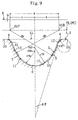
- Figure 9 shows a third embodiment of the present invention.
- the tooth portion 11 of the toothed belt 8 is provided, at its tooth tip end area, with the tooth tip end portion 17 formed of a single circularly arcuate surface for interconnecting the power transmission portions 13, 13 on both the belt length direction sides, as in the second embodiment.
- the tooth groove bottom portion 6 of the pulley tooth groove portion 3 of each of the pulleys 1 and 2 is formed of a single circularly arcuate surface having its center point O2P on the tooth groove width direction centerline C1 and a radius rTP slightly greater than the radius rTB of the tooth tip end portion 17 of the belt tooth portion 11 .
- the tooth groove bottom portion 6 of the tooth groove portion 3 is formed of a circularly arcuate surface having the radius rTP slightly greater than the radius rTB of the circularly arcuate surface of the tooth tip end portion 17 of the belt tooth portion 11 .
- This arrangement enables the belt tooth portion 11 to more smoothly slide into the pulley tooth groove portion 3 , thereby more effectively suppressing the increase in the nonuniformity of velocity of the toothed belt 8 .
- the land portion 10 of the toothed belt 8 may be formed of a circularly arcuate surface.
- the belt land portion 10 be formed of an approximately flat surface which is contiguously interconnected with the flank surfaces of the belt tooth portion 11 flank by the tooth root portions 12 formed of circularly arcuate surfaces arranged symmetrically with each other in respect to the tooth width direction centerline C2.
- the toothed belt 8 having the belt main body 9 made of polyurethane when the pitch of the belt tooth portion 11 is not more than 1.5 mm, the dimensions of a concave portion formed to keep a core cord away from the belt land portion 10 are small and die processing is therefore difficult.
- the core cord is arranged directly over the belt land portion 10 without the provision of such a concave portion.
- it is designed such that the land portion 10 of the toothed belt 8 is made out of contact with the outside diameter portions of the pulleys 1 and 2 . Accordingly, as described above, the arrangement that the land portion 10 of the toothed belt 8 is formed of an approximately flat surface is able to make the position of the core cord stable.
- the tooth groove bottom portion 6 of the tooth groove portion 3 of each of the pulleys 1 and 2 may be formed of an approximately flat surface.
- the toothed belt 8 when wound around the pulleys 1 and 2 , it is possible to make the tooth tip end portion 17 of the belt tooth portion 11 receivable by the tooth groove bottom portion 6 formed of an approximately flat surface having a large area.
- the core cord position (i.e., the pitch line PL) of the toothed belt 8 when wound around the pulleys 1 and 2 can be made stable, therefore reducing the nonuniformity of velocity of the toothed belt 8 to a further extent.
- Each belt material constant was input by actual measurements for belts having a tooth pitch of 2.117 mm and respective constitutional materials (it was considered that the material constant did not vary even when the tooth profile varied).
- the belt main body was set as a quadrangular plane element and the core cord was set as a beam element, and in consideration of friction, the surface that was brought into contact with the pulleys was set as an interface element.
- a model of the pulley surface was a rigid surface.
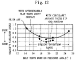
- FIG. 11 shows the data for an example of the present invention (which is equivalent to the first embodiment of the present invention) in which the belt tooth portion comprises tooth tip portions which are arranged symmetrically with each other in relation to the tooth width direction centerline and a tooth crest surface which is formed of an approximately flat surface for interconnecting the tooth tip portions and the maximum pressure angle is between 15 degrees and 25 degrees.
- Figure 11(b) shows the data for an example of a conventional technique in which the maximum pressure angle is 14.4 degrees.
- the belt velocity variation value is represented by an index indicating that the conventional technique example is 1.0.
- the solid line indicates the data for a belt tooth portion having a tooth profile comprising tooth tip portions and a tooth crest surface formed of an approximately flat surface wherein the present invention example covers a maximum pressure range between 15 degrees and 25 degrees.
- the broken line indicates the data for a belt tooth portion having a tooth tip end portion formed of a circularly arcuate surface having its center point on the tooth width direction centerline for interconnecting the power transmission portions, which is equivalent to the second embodiment of the present invention.
- a power transmission apparatus made up of a belt and pulleys was prepared for performing a bench test by a measurement system to measure the nonuniformity of velocity of the belt. More specifically, as examples of the present invention, two toothed belts (Examples 1 and 2 of the present invention) having the same construction (i.e., the construction according to the second embodiment shown in Figure 6) but having different maximum pressure angles (an angle of 17.6 degrees for one and an angle of 19.3 degrees for the other). On the other hand, as an example of the conventional technique, a toothed belt having a construction shown in Figure 17 (the maximum pressure angle: 14.4 degrees) was prepared. The following table shows the dimensions of these toothed belts.
- test toothed belts are made of rubber and has tooth portions of circularly arcuate profile (tooth pitch: 2.117 mm).
- the rubber is chloroprene rubber having a hardness of 70 degrees.
- the core cord is made from glass fiber of a diameter of 0.3 mm.
- the fabric, made from polyamide woolie finish yarn, is RF processed and only its rear side is processed by rubber cement.
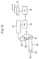
- the measurement system comprises a driving and driven pulleys 41 and 42 which are implemented by toothed pulleys around which each test toothed belt 40 is wound.
- Belt tension is applied by a static load DW to the driven pulley 42 and the driving pulley 41 is rotated in a direction indicated by an arrow in the figure with the driven pulley 42 placed in the noload state.
- the nonuniformity of velocity of the belt 40 is measured by the velocity nonuniformity measurement device 44 .
- the frequency of the velocity nonuniformity thus measured is analyzed by an FFT 45 and the analysis results are fed into a personal computer 46 and then printed out by a printer 47 .
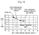
- each belt velocity variation value is an index value in which the conventional technique example (whose maximum pressure angle is 14.4 degrees) is 1.0.
- the maximum pressure angle at where the power transmission portion of the belt tooth flank surface and the tooth root portion are connected together is between an angle of 15 degrees and an angle of 25 degrees, this reduces the nonuniformity of belt velocity to a further extent in comparison with the conventional technique example whose maximum pressure angle is 14.4 degrees. It is preferable that the maximum pressure angle be between 16 degrees and 23 degrees. Further, if the maximum pressure angle is set to fall within the range between 17 degrees and 22 degrees, this achieves a considerable reduction in the nonuniformity of belt velocity. It is optimally preferable that the maximum pressure angle be 19.3 degrees.
- the present invention at the time when a belt tooth portion is about to come into meshing engagement with a pulley tooth groove portion, it is designed such that the contacting of a flank surface of the belt tooth portion with a flank surface of the pulley tooth groove portion is delayed and, in addition, a vertical component of a reaction force produced when the belt tooth portion slides into the pulley tooth groove portion is reduced.
- This allows the belt tooth portion to smoothly slide into pulley tooth groove portion, thereby considerably reducing the nonuniformity of velocity of the toothed belt to provide practically excellent advantages such as improvement in the printing accuracy and image quality of business use equipment such as a printer. Because of the capability of promotion of the improvement in the performance of business use equipment, the industrial applicability of the present invention is high.
Landscapes
- Engineering & Computer Science (AREA)
- General Engineering & Computer Science (AREA)
- Mechanical Engineering (AREA)
- Devices For Conveying Motion By Means Of Endless Flexible Members (AREA)
- Pulleys (AREA)
Applications Claiming Priority (5)
| Application Number | Priority Date | Filing Date | Title |
|---|---|---|---|
| JP8093699 | 1999-03-25 | ||
| JP8093699 | 1999-03-25 | ||
| JP11128707A JP2000337444A (ja) | 1999-03-25 | 1999-05-10 | 歯付ベルト及び歯付ベルト伝動装置並びに事務用機器 |
| JP12870799 | 1999-05-10 | ||
| PCT/JP2000/001798 WO2000058644A1 (fr) | 1999-03-25 | 2000-03-23 | Courroie crantee, dispositif de transmission a courroie crantee et machines de bureau |
Publications (2)
| Publication Number | Publication Date |
|---|---|
| EP1083365A1 true EP1083365A1 (fr) | 2001-03-14 |
| EP1083365A4 EP1083365A4 (fr) | 2006-06-07 |
Family
ID=26421897
Family Applications (1)
| Application Number | Title | Priority Date | Filing Date |
|---|---|---|---|
| EP00911327A Withdrawn EP1083365A4 (fr) | 1999-03-25 | 2000-03-23 | Courroie crantee, dispositif de transmission a courroie crantee et machines de bureau |
Country Status (5)
| Country | Link |
|---|---|
| US (1) | US6485384B1 (fr) |
| EP (1) | EP1083365A4 (fr) |
| JP (1) | JP2000337444A (fr) |
| TW (1) | TW461942B (fr) |
| WO (1) | WO2000058644A1 (fr) |
Cited By (1)
| Publication number | Priority date | Publication date | Assignee | Title |
|---|---|---|---|---|
| WO2018164939A1 (fr) * | 2017-03-07 | 2018-09-13 | Gates Corporation | Système à courroie crantée et pignon |
Families Citing this family (20)
| Publication number | Priority date | Publication date | Assignee | Title |
|---|---|---|---|---|
| JP3964725B2 (ja) * | 2002-01-21 | 2007-08-22 | 本田技研工業株式会社 | 歯付きベルト伝動装置 |
| US8932165B2 (en) * | 2006-03-31 | 2015-01-13 | The Gates Corporation | Toothed power transmission belt |
| US20080258550A1 (en) * | 2007-04-23 | 2008-10-23 | Mr. TIMOTHY DAVID WEBSTER | Hybrid Combination of Rubber Track with Road Wheels for a Vehicle |
| US20090156341A1 (en) * | 2007-12-14 | 2009-06-18 | John Gaynor | Belt |
| RU2508485C2 (ru) * | 2009-06-23 | 2014-02-27 | Чжэцзян Кинглэнд Трансмишн Индастри Ко., Лтд. | Система составной клиноременной передачи, сочетающая фрикционную передачу и передачу зацеплением |
| JP5931028B2 (ja) * | 2013-08-30 | 2016-06-08 | 三ツ星ベルト株式会社 | 自転車用歯付ベルト駆動装置 |
| JP6324336B2 (ja) * | 2014-03-31 | 2018-05-16 | 三ツ星ベルト株式会社 | 歯付きベルト |
| GB2587297B (en) | 2015-03-31 | 2021-08-04 | Fisher & Paykel Healthcare Ltd | A user interface and system for supplying gases to an airway |
| DE102016001972A1 (de) * | 2016-02-22 | 2017-08-24 | Contitech Antriebssysteme Gmbh | Zahnriementrieb |
| CN109196246B (zh) * | 2016-05-20 | 2019-09-24 | 阪东化学株式会社 | 带齿v带及使用了该带齿v带的传动系统 |
| US11015694B2 (en) | 2016-06-09 | 2021-05-25 | Contitech Antriebssysteme Gmbh | Bushing and hub to prevent back-rotation |
| US10989293B2 (en) | 2016-06-09 | 2021-04-27 | Contitech Antriebssysteme Gmbh | Non-metal sprocket and bushing apparatus |
| KR20240157114A (ko) | 2016-08-11 | 2024-10-31 | 피셔 앤 페이켈 핼스케어 리미티드 | 압궤 가능 도관, 환자 인터페이스 및 헤드기어 연결부 |
| JP6773969B2 (ja) * | 2016-09-02 | 2020-10-21 | 株式会社椿本チエイン | チェーン伝動機構 |
| JP6829388B2 (ja) * | 2017-02-27 | 2021-02-10 | 株式会社椿本チエイン | 歯付ベルト伝動装置 |
| US10687468B1 (en) * | 2018-12-18 | 2020-06-23 | Contitech Antriebssysteme Gmbh | Flexible synchronous toothed belt with narrow splice |
| US11585423B2 (en) | 2020-10-03 | 2023-02-21 | Contitech Antriebssysteme Gmbh | Composite sprocket |
| WO2022230762A1 (fr) * | 2021-04-27 | 2022-11-03 | 三ツ星ベルト株式会社 | Courroie crantée et mécanisme de transmission à courroie |
| EP4332410A4 (fr) * | 2021-04-30 | 2025-04-09 | Bando Chemical Industries, Ltd. | Courroie dentée |
| JP7406051B1 (ja) * | 2022-07-28 | 2023-12-26 | バンドー化学株式会社 | 歯付ベルト |
Family Cites Families (21)
| Publication number | Priority date | Publication date | Assignee | Title |
|---|---|---|---|---|
| US3756091A (en) * | 1970-02-19 | 1973-09-04 | Uniroyal Inc | Positive power transmission system |
| SE372917B (fr) * | 1973-05-04 | 1975-01-20 | C G R Ossbahr | |
| GB1453716A (en) | 1973-07-20 | 1976-10-27 | Goodyear Tire & Rubber | Circular side positive drive belt teeth |
| US4147069A (en) * | 1976-10-01 | 1979-04-03 | Fmc Corporation | Geared belt for positive drive transmission |
| ZA786820B (en) * | 1977-12-14 | 1979-11-28 | Uniroyal Inc | Mechanical power transmission system |
| JPS56141245U (fr) | 1980-03-26 | 1981-10-24 | ||
| US4515577A (en) * | 1982-10-20 | 1985-05-07 | Uniroyal, Inc. | Low backlash-high-torque power transmission system and toothed belt used therein |
| IN162773B (fr) * | 1983-10-12 | 1988-07-09 | Mitsuboshi Belting Ltd | |
| DE8622383U1 (de) * | 1986-08-21 | 1987-08-20 | Arnold Müller GmbH & Co KG, 73230 Kirchheim | Einrichtung zur Erzeugung von Linearbewegungen |
| JPS63297838A (ja) | 1987-05-29 | 1988-12-05 | Mitsuboshi Belting Ltd | 歯付ベルトの駆動装置 |
| JPS6474341A (en) * | 1987-09-14 | 1989-03-20 | Mitsuboshi Belting Ltd | Driving device of toothed belt |
| JPH0621604B2 (ja) * | 1988-01-27 | 1994-03-23 | バンドー化学株式会社 | 歯付ベルトおよびそのベルトを使用する動力伝達装置 |
| DE3808518A1 (de) * | 1988-03-15 | 1989-09-28 | Erich Wallich | Mehrfachquerfoerderer |
| JPH01279135A (ja) | 1988-04-28 | 1989-11-09 | Mitsuboshi Belting Ltd | 歯付ベルト及びこれを用いた駆動装置 |
| IT1229809B (it) * | 1988-11-11 | 1991-09-13 | Pirelli Transmissioni Ind Spa | Cinghia dentata e relativa trasmissione. |
| IT1227627B (it) * | 1988-11-29 | 1991-04-23 | Pirelli Transmissioni Ind Spa | Puleggia dentata e relativa trasmissione. |
| JPH0394272A (ja) | 1989-09-07 | 1991-04-19 | Toshiba Corp | 画像形成装置 |
| JP2791719B2 (ja) | 1991-08-14 | 1998-08-27 | 株式会社エース電研 | 遊技機用メダル体給送装置 |
| US5405299A (en) * | 1992-12-29 | 1995-04-11 | Bridgestone Corporation | Toothed belt and toothed belt-adapted pulley |
| JPH06307522A (ja) | 1993-02-24 | 1994-11-01 | Bridgestone Corp | 歯付ベルト用プーリー |
| IT1265351B1 (it) | 1993-11-26 | 1996-11-22 | Dayco Pti Spa | Trasmissione a cinghia dentata per il comando di alberi di equilibratura dinamica in motori endotermici |
-
1999
- 1999-05-10 JP JP11128707A patent/JP2000337444A/ja active Pending
-
2000
- 2000-03-23 EP EP00911327A patent/EP1083365A4/fr not_active Withdrawn
- 2000-03-23 WO PCT/JP2000/001798 patent/WO2000058644A1/fr not_active Ceased
- 2000-03-23 US US09/673,259 patent/US6485384B1/en not_active Expired - Lifetime
- 2000-03-24 TW TW089105546A patent/TW461942B/zh not_active IP Right Cessation
Cited By (2)
| Publication number | Priority date | Publication date | Assignee | Title |
|---|---|---|---|---|
| WO2018164939A1 (fr) * | 2017-03-07 | 2018-09-13 | Gates Corporation | Système à courroie crantée et pignon |
| AU2018230924B2 (en) * | 2017-03-07 | 2020-10-15 | Gates Corporation | Toothed belt and sprocket system |
Also Published As
| Publication number | Publication date |
|---|---|
| TW461942B (en) | 2001-11-01 |
| US6485384B1 (en) | 2002-11-26 |
| EP1083365A4 (fr) | 2006-06-07 |
| WO2000058644A1 (fr) | 2000-10-05 |
| JP2000337444A (ja) | 2000-12-05 |
Similar Documents
| Publication | Publication Date | Title |
|---|---|---|
| US6485384B1 (en) | Toothed belt, toothed belt power transmission apparatus, and business equipment employing the same | |
| JP4010551B2 (ja) | ハス歯ベルト伝動装置 | |
| US7874952B2 (en) | Power transmission chain and power transmission device | |
| EP0148645B1 (fr) | Système de transmission de puissance et sa courroie crantée | |
| EP0926394B1 (fr) | Chaíne à dents à double engagement et roue dentée pour engagement avec la chaíne sur son pourtour | |
| JPS591896B2 (ja) | 歯付ベルトの伝動装置 | |
| US20010053727A1 (en) | Belt transmission system | |
| JPS635626B2 (fr) | ||
| JP4387002B2 (ja) | 歯付ベルト駆動装置 | |
| JP4550985B2 (ja) | 歯付ベルト伝動装置並びに事務用機器 | |
| JP2002098202A (ja) | 歯付ベルト伝動装置及び事務用機器 | |
| JP3601987B2 (ja) | プーリおよびこのプーリを用いた動力伝達システム | |
| US20110028258A1 (en) | High load drive v-belt | |
| JP3838819B2 (ja) | 歯付ベルト及び歯付ベルト伝動装置並びに事務用機器 | |
| EP1236928B1 (fr) | Courroie de transmission et son procédé de fabrication | |
| JP2002098201A (ja) | 歯付ベルト伝動装置及び事務用機器 | |
| US7016818B1 (en) | Method of evaluating the power transmission ability of frictional power transmission belt and method of aiding the designing for belt drive system | |
| JP2002098196A (ja) | 歯付ベルト及び歯付ベルト伝動装置並びに事務用機器 | |
| US20150005121A1 (en) | V-belt for high load transmission | |
| JP2002195351A (ja) | 高負荷伝動ベルト及び高負荷伝動ベルト用ブロック | |
| JP2002070992A (ja) | ベルト伝動装置 | |
| KR20180016256A (ko) | 체인 전동 장치 및 체인 가이드 | |
| US6334831B1 (en) | Drive belt, transverse element therefor and transmission in which this is used | |
| US20150005124A1 (en) | V-belt for high load transmission | |
| JP2004028200A (ja) | 高負荷伝動ベルト |
Legal Events
| Date | Code | Title | Description |
|---|---|---|---|
| PUAI | Public reference made under article 153(3) epc to a published international application that has entered the european phase |
Free format text: ORIGINAL CODE: 0009012 |
|
| 17P | Request for examination filed |
Effective date: 20001024 |
|
| AK | Designated contracting states |
Kind code of ref document: A1 Designated state(s): AT BE CH CY DE DK ES FI FR GB GR IE IT LI LU MC NL PT SE |
|
| RBV | Designated contracting states (corrected) |
Designated state(s): DE FR GB IT |
|
| A4 | Supplementary search report drawn up and despatched |
Effective date: 20060503 |
|
| 17Q | First examination report despatched |
Effective date: 20061115 |
|
| STAA | Information on the status of an ep patent application or granted ep patent |
Free format text: STATUS: THE APPLICATION IS DEEMED TO BE WITHDRAWN |
|
| 18D | Application deemed to be withdrawn |
Effective date: 20110819 |