EP1083374A2 - Dispositif de connexion pour tuyau d'un cours d'eau - Google Patents
Dispositif de connexion pour tuyau d'un cours d'eau Download PDFInfo
- Publication number
- EP1083374A2 EP1083374A2 EP00307102A EP00307102A EP1083374A2 EP 1083374 A2 EP1083374 A2 EP 1083374A2 EP 00307102 A EP00307102 A EP 00307102A EP 00307102 A EP00307102 A EP 00307102A EP 1083374 A2 EP1083374 A2 EP 1083374A2
- Authority
- EP
- European Patent Office
- Prior art keywords
- connection
- coupler
- groove
- engaging
- pipes
- Prior art date
- Legal status (The legal status is an assumption and is not a legal conclusion. Google has not performed a legal analysis and makes no representation as to the accuracy of the status listed.)
- Withdrawn
Links
- 230000008878 coupling Effects 0.000 claims abstract description 13
- 238000010168 coupling process Methods 0.000 claims abstract description 13
- 238000005859 coupling reaction Methods 0.000 claims abstract description 13
- 230000002265 prevention Effects 0.000 claims description 8
- 238000009434 installation Methods 0.000 description 3
- 238000010276 construction Methods 0.000 description 2
- 238000002360 preparation method Methods 0.000 description 2
- XLYOFNOQVPJJNP-UHFFFAOYSA-N water Substances O XLYOFNOQVPJJNP-UHFFFAOYSA-N 0.000 description 2
- 240000007594 Oryza sativa Species 0.000 description 1
- 235000007164 Oryza sativa Nutrition 0.000 description 1
- 238000007792 addition Methods 0.000 description 1
- 239000002184 metal Substances 0.000 description 1
- 238000000034 method Methods 0.000 description 1
- 238000012986 modification Methods 0.000 description 1
- 230000004048 modification Effects 0.000 description 1
- 235000009566 rice Nutrition 0.000 description 1
- 238000006467 substitution reaction Methods 0.000 description 1
Images


Classifications
-
- F—MECHANICAL ENGINEERING; LIGHTING; HEATING; WEAPONS; BLASTING
- F16—ENGINEERING ELEMENTS AND UNITS; GENERAL MEASURES FOR PRODUCING AND MAINTAINING EFFECTIVE FUNCTIONING OF MACHINES OR INSTALLATIONS; THERMAL INSULATION IN GENERAL
- F16L—PIPES; JOINTS OR FITTINGS FOR PIPES; SUPPORTS FOR PIPES, CABLES OR PROTECTIVE TUBING; MEANS FOR THERMAL INSULATION IN GENERAL
- F16L25/00—Construction or details of pipe joints not provided for in, or of interest apart from, groups F16L13/00 - F16L23/00
-
- F—MECHANICAL ENGINEERING; LIGHTING; HEATING; WEAPONS; BLASTING
- F16—ENGINEERING ELEMENTS AND UNITS; GENERAL MEASURES FOR PRODUCING AND MAINTAINING EFFECTIVE FUNCTIONING OF MACHINES OR INSTALLATIONS; THERMAL INSULATION IN GENERAL
- F16L—PIPES; JOINTS OR FITTINGS FOR PIPES; SUPPORTS FOR PIPES, CABLES OR PROTECTIVE TUBING; MEANS FOR THERMAL INSULATION IN GENERAL
- F16L25/00—Construction or details of pipe joints not provided for in, or of interest apart from, groups F16L13/00 - F16L23/00
- F16L25/0036—Joints for corrugated pipes
-
- F—MECHANICAL ENGINEERING; LIGHTING; HEATING; WEAPONS; BLASTING
- F16—ENGINEERING ELEMENTS AND UNITS; GENERAL MEASURES FOR PRODUCING AND MAINTAINING EFFECTIVE FUNCTIONING OF MACHINES OR INSTALLATIONS; THERMAL INSULATION IN GENERAL
- F16L—PIPES; JOINTS OR FITTINGS FOR PIPES; SUPPORTS FOR PIPES, CABLES OR PROTECTIVE TUBING; MEANS FOR THERMAL INSULATION IN GENERAL
- F16L21/00—Joints with sleeve or socket
- F16L21/06—Joints with sleeve or socket with a divided sleeve or ring clamping around the pipe ends
- F16L21/065—Joints with sleeve or socket with a divided sleeve or ring clamping around the pipe ends tightened by tangentially-arranged threaded pins
Definitions
- the present invention relates to a connection apparatus for a waterway pipe, and in particular to a connection apparatus which is capable of fabricating a length pipe by connecting a plurality of pipes each having a certain length.
- a waterway is used for continuously providing water from a river, a water reservoir, etc. to a rice field.
- the waterway is formed by digging a certain area using a channel shape concrete.
- the waterway is formed on the ground, and the nature and the environment are damaged.
- the pipes 100 each having a certain length are connected using a coupler 200.
- the coupler 200 surrounds each end of the pipes 100, and then the both ends of the coupler 200 are connected using a bolt 300 and a nut 400.
- connection apparatus for a waterway pipe which overcomes the problems encountered during a conventional coupler connection work.
- connection apparatus for a waterway pipe which includes a plurality of pipes each having both ends which are connected in series, a coupler having protruded both ends and a connection member having a plurality of connection grooves for surrounding the connection portions of the pipes, an engaging member which passes through the connection groove, and an engaging member having one end inserted into the connection groove and the other end contacting with one side of the connection member, so that the coupling member moves backwardly and forward by a rotation force of the engaging member, and the coupler is tightened and loosened.
- connection groove formed at the connection member is polygonal.
- the engaging member includes a support member contacting with one side of the connection member, an engaging hole formed at a center portion of the support member and threadely engaged with the support member, and a rotation prevention member integrally formed with one side of the support member and having an outer surface corresponding to an inner surface of a polygonal connection groove.
- the rotation prevention member includes a vertical cut-away groove formed at both sides of the center portion of the same, and a fixing member inserted into the cut-away groove.
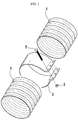
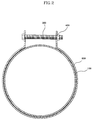
- a connection apparatus for a waterway pipe includes a coupler 20 which surrounds the connection portions of a pipe 10 which is connected.
- the coupler 20 includes a connection member 21 having protruded both ends, and a plurality of connection grooves 22 are formed at a portion of the connection member 21.
- the construction of the coupler 20 is similar to the construction of the conventional coupler 200.
- An engaging member 30(or bolt) passes through the connection groove 22 formed at the coupler 20.
- the engaging member 30 is fixed by an coupling member 40(or nut).
- connection groove 22 One end of the coupling member 40 is inserted by the connection groove 22, and the other end of the same contacts with one side of the connection member 21, so that the coupling member 40 moves forward and backwardly by the rotation force when rotating the engaging member 30. Therefore, the coupler 20 is tightened and loosened thereby.
- connection groove 22 of one side formed at the connection member 21 is polygonally formed.
- the coupling member 40 includes a support member 41 supported by one side of the connection member 21, an engaging hole 42 formed at the center portion of the support member 41 and threadely engaged with the engaging member 30, and a rotation prevention member 43 having an outer surface corresponding to an inner surface of the connection groove 22 and preventing a rotation by its polygonal structure.
- the rotation prevention member 43 includes a vertical cut-away groove 44 at both sides of the center portion, and the fixing member 45 is inserted into the cut-away groove 44.
- each pipe 10 is arranged in series, and then the coupler 20 surrounds the connection portions of the pipe.
- the engaging member 30 passes through the connection groove 22 formed at one side of the connection member, and the engaging member 30 is protruded from the outer side of the polygonal connection groove 22 formed at the connection member 21.
- the coupling member 40 which has the same function as the nut is installed to correspond with the engaging member 30 protruded to the other side of the connection member 21.
- the support member 41 formed at one end of the coupling member 40 contacts with the outer surface of the connection member 21, and the rotation prevention member 43 provided at one side is inserted into the polygonal connection groove 22 formed at the connection member 21 of the other side.
Landscapes
- Engineering & Computer Science (AREA)
- General Engineering & Computer Science (AREA)
- Mechanical Engineering (AREA)
- Joints With Sleeves (AREA)
- Joints Allowing Movement (AREA)
- Joints That Cut Off Fluids, And Hose Joints (AREA)
- Quick-Acting Or Multi-Walled Pipe Joints (AREA)
Applications Claiming Priority (2)
| Application Number | Priority Date | Filing Date | Title |
|---|---|---|---|
| KR1019990037973A KR100318038B1 (ko) | 1999-09-07 | 1999-09-07 | 수로용 관의 연결장치 |
| KR9937973 | 1999-09-07 |
Publications (2)
| Publication Number | Publication Date |
|---|---|
| EP1083374A2 true EP1083374A2 (fr) | 2001-03-14 |
| EP1083374A3 EP1083374A3 (fr) | 2002-05-22 |
Family
ID=19610460
Family Applications (1)
| Application Number | Title | Priority Date | Filing Date |
|---|---|---|---|
| EP00307102A Withdrawn EP1083374A3 (fr) | 1999-09-07 | 2000-08-18 | Dispositif de connexion pour tuyau d'un cours d'eau |
Country Status (8)
| Country | Link |
|---|---|
| US (1) | US6447029B1 (fr) |
| EP (1) | EP1083374A3 (fr) |
| JP (1) | JP3422977B2 (fr) |
| KR (1) | KR100318038B1 (fr) |
| CN (1) | CN1150389C (fr) |
| ID (1) | ID27222A (fr) |
| MY (1) | MY125257A (fr) |
| SG (1) | SG90154A1 (fr) |
Families Citing this family (12)
| Publication number | Priority date | Publication date | Assignee | Title |
|---|---|---|---|---|
| DE10314999B3 (de) * | 2003-04-02 | 2004-12-23 | Rasmussen Gmbh | Gelenkhülse für eine Schelle |
| USD571440S1 (en) * | 2005-07-25 | 2008-06-17 | Kanaflex Corporation Inc. | Joint for a pipe connector |
| USD574472S1 (en) * | 2005-07-25 | 2008-08-05 | Kanaflex Corporation, Inc. | Pipe connector |
| GB2446814A (en) * | 2007-02-21 | 2008-08-27 | Norma Products Ltd | Annular clamp with moveable captive nut |
| CN101982635A (zh) * | 2010-10-08 | 2011-03-02 | 深圳市华星光电技术有限公司 | 楼板通孔模板装置及其紧固组件 |
| DE102011009536B4 (de) * | 2011-01-27 | 2013-09-19 | Norma Germany Gmbh | Spannschelle |
| CN102644811B (zh) * | 2011-02-16 | 2014-10-29 | 美国胜赛斯公司 | 具有波浪形保护件的和具有带有压力导向槽的环形垫圈的开环式压盖管道连接件 |
| USD717409S1 (en) * | 2012-08-10 | 2014-11-11 | Jackie Ray Buchanan | Coupling device |
| CN104180167A (zh) * | 2014-07-25 | 2014-12-03 | 刘影 | 一种用于水管连接器的报警装置 |
| CN104565611B (zh) * | 2014-12-31 | 2017-12-19 | 东莞市华荣涂装设备有限公司 | 用于燃烧机同口径发热管对接的对接装置及对接方法 |
| CN112049995A (zh) * | 2020-09-03 | 2020-12-08 | 安徽恒振电力科技有限公司 | 一种双复合钢塑复合管及其制造方法 |
| CN115899597A (zh) * | 2022-11-10 | 2023-04-04 | 深圳市众博泰电子科技有限公司 | 一种进水警示连接器 |
Citations (2)
| Publication number | Priority date | Publication date | Assignee | Title |
|---|---|---|---|---|
| US1872616A (en) * | 1930-04-10 | 1932-08-16 | Smith Corp A O | Connecting metal plate |
| US4906150A (en) * | 1985-07-17 | 1990-03-06 | Bennett Bruce A | Locking fastener |
Family Cites Families (12)
| Publication number | Priority date | Publication date | Assignee | Title |
|---|---|---|---|---|
| US3411748A (en) * | 1967-04-25 | 1968-11-19 | Earl W. Fortune | Band expander and contractor for drain pipes |
| US3737959A (en) * | 1971-10-29 | 1973-06-12 | Smith Blair Inc | Pipe clamp made of non-cast materials |
| US4174985A (en) * | 1977-01-19 | 1979-11-20 | Buidry Kirby J | Process for manufacturing coupling gaskets for helically corrugated spiral pipe |
| CA1192586A (fr) * | 1984-05-01 | 1985-08-27 | Frederick W. Roberts | Raccord a boulon |
| US4734001A (en) * | 1985-07-17 | 1988-03-29 | Bennett Bruce A | Locking fastener |
| US4790574A (en) * | 1987-01-16 | 1988-12-13 | Donaldson Company, Inc. | Apparatus for coupling tubular members |
| CA2001088C (fr) * | 1988-11-03 | 1995-05-16 | Ramon Palau Dominguez | Serre-cable avec vis de blocage |
| DE4200265A1 (de) * | 1991-01-15 | 1992-07-16 | Rene Dick | Rohrschelle |
| DE9102571U1 (de) * | 1991-03-05 | 1991-05-23 | Friedrich Wilhelm und Gustav Kettling GmbH, 5880 Lüdenscheid | Rauchrohrschelle |
| JP2602515Y2 (ja) * | 1993-06-25 | 2000-01-17 | 金尾 茂樹 | 管継手 |
| DE29510768U1 (de) * | 1995-07-03 | 1995-09-14 | Suevia Haiges Gmbh & Co, 74366 Kirchheim | Überschieb-Muffe mit Rohrschelle o.dgl. für Rohrverbindungen oder -anschlüsse |
| US5961161A (en) * | 1998-03-13 | 1999-10-05 | Mage Ag | Pipe connector clamp |
-
1999
- 1999-09-07 KR KR1019990037973A patent/KR100318038B1/ko not_active Expired - Lifetime
-
2000
- 2000-08-01 US US09/630,167 patent/US6447029B1/en not_active Expired - Fee Related
- 2000-08-03 SG SG200004351A patent/SG90154A1/en unknown
- 2000-08-11 CN CNB001208934A patent/CN1150389C/zh not_active Expired - Fee Related
- 2000-08-15 ID IDP20000680D patent/ID27222A/id unknown
- 2000-08-16 JP JP2000246613A patent/JP3422977B2/ja not_active Expired - Fee Related
- 2000-08-17 MY MYPI20003759 patent/MY125257A/en unknown
- 2000-08-18 EP EP00307102A patent/EP1083374A3/fr not_active Withdrawn
Patent Citations (2)
| Publication number | Priority date | Publication date | Assignee | Title |
|---|---|---|---|---|
| US1872616A (en) * | 1930-04-10 | 1932-08-16 | Smith Corp A O | Connecting metal plate |
| US4906150A (en) * | 1985-07-17 | 1990-03-06 | Bennett Bruce A | Locking fastener |
Also Published As
| Publication number | Publication date |
|---|---|
| ID27222A (id) | 2001-03-08 |
| EP1083374A3 (fr) | 2002-05-22 |
| MY125257A (en) | 2006-07-31 |
| CN1287239A (zh) | 2001-03-14 |
| SG90154A1 (en) | 2002-07-23 |
| US6447029B1 (en) | 2002-09-10 |
| KR20010026597A (ko) | 2001-04-06 |
| JP3422977B2 (ja) | 2003-07-07 |
| KR100318038B1 (ko) | 2001-12-22 |
| CN1150389C (zh) | 2004-05-19 |
| JP2001090881A (ja) | 2001-04-03 |
Similar Documents
| Publication | Publication Date | Title |
|---|---|---|
| EP1083374A2 (fr) | Dispositif de connexion pour tuyau d'un cours d'eau | |
| CA2365069A1 (fr) | Systeme d'installation de fondation d'un batiment | |
| JP4717301B2 (ja) | 管路における不平均力の支持装置 | |
| KR200318113Y1 (ko) | 흄관용 받침부재 | |
| JP7299042B2 (ja) | 耐震管推進敷設工法用推進力伝達装置 | |
| JP7144241B2 (ja) | 耐震管推進敷設工法用推進力伝達装置 | |
| EP0165240A1 (fr) | Joint de tuyau flexible | |
| JPH1121882A (ja) | 杭の接続構造 | |
| JP7213066B2 (ja) | 耐震管推進敷設工法用推進力伝達装置 | |
| JP2000310368A (ja) | 管継手部の構造とそれに使用するパッキン | |
| JP3590364B2 (ja) | 鋼管杭用の接続具 | |
| JP2843889B2 (ja) | コンクリートセグメント及びコンクリートセグメントの継手構造 | |
| JP6837338B2 (ja) | 鋼製セグメントのリング継手構造及びその連結方法 | |
| KR100281349B1 (ko) | 곡선터널 굴착용 추진관의 하중분산 장치 | |
| KR100696402B1 (ko) | 내진형 관 연결구 | |
| KR200268425Y1 (ko) | 도로 경사면의 지중 콘크리트 흄관의 연결구조 | |
| JP7284027B2 (ja) | 推進敷設工法用推進力伝達装置 | |
| JP2002235884A (ja) | 耐震継手ならびに耐震管路 | |
| KR200261383Y1 (ko) | 케이블 매설 파이프용 연결구 | |
| JPH0681998B2 (ja) | マンホールの分岐管接続用ゴム筒の固定リング | |
| KR200283848Y1 (ko) | 관 연결구 | |
| JP4230403B2 (ja) | セグメントの継手構造 | |
| KR200181891Y1 (ko) | 하수관 분기 연결관 | |
| JPH07332553A (ja) | 管継手の構造 | |
| KR200355612Y1 (ko) | 파이프 연결 장치 |
Legal Events
| Date | Code | Title | Description |
|---|---|---|---|
| PUAI | Public reference made under article 153(3) epc to a published international application that has entered the european phase |
Free format text: ORIGINAL CODE: 0009012 |
|
| 17P | Request for examination filed |
Effective date: 20000918 |
|
| AK | Designated contracting states |
Kind code of ref document: A2 Designated state(s): AT BE CH CY DE DK ES FI FR GB GR IE IT LI LU MC NL PT SE |
|
| AX | Request for extension of the european patent |
Free format text: AL;LT;LV;MK;RO;SI |
|
| PUAL | Search report despatched |
Free format text: ORIGINAL CODE: 0009013 |
|
| AX | Request for extension of the european patent |
Free format text: AL;LT;LV;MK;RO;SI |
|
| RIC1 | Information provided on ipc code assigned before grant |
Free format text: 7F 16L 21/06 A, 7F 16L 25/00 B |
|
| AKX | Designation fees paid |
Designated state(s): DE FR GB IT |
|
| 17Q | First examination report despatched |
Effective date: 20031230 |
|
| STAA | Information on the status of an ep patent application or granted ep patent |
Free format text: STATUS: THE APPLICATION IS DEEMED TO BE WITHDRAWN |
|
| 18D | Application deemed to be withdrawn |
Effective date: 20050909 |