EP1083391A2 - Axiallüfter für Klimaanlage - Google Patents
Axiallüfter für Klimaanlage Download PDFInfo
- Publication number
- EP1083391A2 EP1083391A2 EP99125720A EP99125720A EP1083391A2 EP 1083391 A2 EP1083391 A2 EP 1083391A2 EP 99125720 A EP99125720 A EP 99125720A EP 99125720 A EP99125720 A EP 99125720A EP 1083391 A2 EP1083391 A2 EP 1083391A2
- Authority
- EP
- European Patent Office
- Prior art keywords
- fan
- axial flow
- flow fan
- hub
- blade
- Prior art date
- Legal status (The legal status is an assumption and is not a legal conclusion. Google has not performed a legal analysis and makes no representation as to the accuracy of the status listed.)
- Granted
Links
Images


Classifications
-
- F—MECHANICAL ENGINEERING; LIGHTING; HEATING; WEAPONS; BLASTING
- F04—POSITIVE - DISPLACEMENT MACHINES FOR LIQUIDS; PUMPS FOR LIQUIDS OR ELASTIC FLUIDS
- F04D—NON-POSITIVE-DISPLACEMENT PUMPS
- F04D29/00—Details, component parts, or accessories
- F04D29/26—Rotors specially for elastic fluids
- F04D29/32—Rotors specially for elastic fluids for axial flow pumps
- F04D29/38—Blades
- F04D29/384—Blades characterised by form
-
- F—MECHANICAL ENGINEERING; LIGHTING; HEATING; WEAPONS; BLASTING
- F24—HEATING; RANGES; VENTILATING
- F24F—AIR-CONDITIONING; AIR-HUMIDIFICATION; VENTILATION; USE OF AIR CURRENTS FOR SCREENING
- F24F7/00—Ventilation
- F24F7/007—Ventilation with forced flow
-
- Y—GENERAL TAGGING OF NEW TECHNOLOGICAL DEVELOPMENTS; GENERAL TAGGING OF CROSS-SECTIONAL TECHNOLOGIES SPANNING OVER SEVERAL SECTIONS OF THE IPC; TECHNICAL SUBJECTS COVERED BY FORMER USPC CROSS-REFERENCE ART COLLECTIONS [XRACs] AND DIGESTS
- Y10—TECHNICAL SUBJECTS COVERED BY FORMER USPC
- Y10S—TECHNICAL SUBJECTS COVERED BY FORMER USPC CROSS-REFERENCE ART COLLECTIONS [XRACs] AND DIGESTS
- Y10S416/00—Fluid reaction surfaces, i.e. impellers
- Y10S416/02—Formulas of curves
-
- Y—GENERAL TAGGING OF NEW TECHNOLOGICAL DEVELOPMENTS; GENERAL TAGGING OF CROSS-SECTIONAL TECHNOLOGIES SPANNING OVER SEVERAL SECTIONS OF THE IPC; TECHNICAL SUBJECTS COVERED BY FORMER USPC CROSS-REFERENCE ART COLLECTIONS [XRACs] AND DIGESTS
- Y10—TECHNICAL SUBJECTS COVERED BY FORMER USPC
- Y10S—TECHNICAL SUBJECTS COVERED BY FORMER USPC CROSS-REFERENCE ART COLLECTIONS [XRACs] AND DIGESTS
- Y10S416/00—Fluid reaction surfaces, i.e. impellers
- Y10S416/05—Variable camber or chord length
Definitions
- the present invention relates to an axial flow fan for an air conditioner, and in particular to an axial flow fan for an air conditioner which is capable of changing the shape of blades by varying a design factor such as a chord length, a sweep angle, etc., generating an enough flowing amount of a fan for implementing an efficient heat radiation of a heat exchanger, and decreasing a noise which occurs during an air flowing operation of the fan, so that it is possible to implement a high efficiency and low noise fan system.
- a design factor such as a chord length, a sweep angle, etc.
- An air conditioner is an apparatus capable of processing air and supplying the processed air into a certain interior for thereby maintaining air in a room or a building in a clean state and is classified into an integration type and a separation type.
- the integration type air conditioner having an integrated cooling and heating function is installed using a fixing apparatus by forming a hole at a window or a wall.
- a cooling apparatus is installed inside a room as an indoor unit, and a heat radiating and compression apparatus is installed outside the room as an outdoor unit.
- the cooling apparatus and the heat radiating and compression apparatus are connected by a refrigerant pipe.
- the separation type air conditioner will be explained.
- the separation type air conditioner includes an indoor unit for performing a cooling function, an outdoor unit for performing a heat radiating and compression function, and a refrigerant pipe for connecting the indoor and outdoor units.
- the indoor unit absorbs heat in a certain interior, and the outdoor unit radiates heat, which corresponds to a sum of heat absorbed in the interior and heat that a compressor radiates to refrigerant, to the outside.
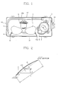
- the outdoor unit of the conventional separation type air conditioner includes an axial flow fan 1 for sucking an indoor air, generating a certain flow of air used for a heat exchange by the outdoor unit and discharging air, a motor 3 for providing a driving force to the axial flow fan 1, a compressor 5 for compressing a low temperature and pressure vapor state refrigerant flown from the indoor unit and changing the same into a high temperature and pressure vapor state refrigerant, an outdoor heat exchanger 7 for exchanging heat between the high temperature and pressure vapor state refrigerant and the air sucked by the axial flow fan 1 for thereby condensing the same into an ambient temperature and high pressure liquid state refrigerant, an accumulator 8 installed at a suction portion of the compressor 5 for removing an impurity of the refrigerant and preventing the liquid state refrigerant from being flown into the compressor 5, and a casing 10 for receiving the above-described elements therein.
- the casing 10 includes a front panel 11 for forming a front surface of the outdoor unit, and a rear panel 13 for forming both side surface and a rear surface.
- the rear panel 13 includes a suction port 13a for sucking an external air into the interior of the casing 10
- the front panel 11 includes a discharge port 11a for discharging the inner air of the casing 10 to the outside.
- a protection grille 12 is installed at a portion of the discharge port 11a for preventing an access of the axial flow fan 1 which is rotated at a high speed.
- reference numeral 4 presents a shroud 4 which guides the flow of air discharged from the discharge port 11a of the front panel 11 by the axial flow fan 1, and reference numeral 6 represents a noise absorbing material which surrounds the compressor 5 for decreasing noises of the compressor 5.
- the air having the thusly increased temperature is discharged to the outside by the axial flow fan 1.
- the air sucked into the interior of the casing 10 through the suction port 13a of the rear panel 13 of the outdoor heat exchanger 7 is discharged to the outside through the axial flow fan 1 and the discharge port 11a of the front panel 11.
- the compressor 5 compresses the refrigerant
- the refrigerant circulates through the indoor/outdoor space connection refrigerant pipe which connects the indoor unit and the outdoor unit, so that the refrigerant is flown into the heat exchanger 7.
- the axial flow fan 1 is rotated by the driving operation of the motor 3, the air is sucked through the suction port 13a, and a certain air flux is formed in the air discharged through the discharge port 11a.
- the thusly formed flux air contacts with the outdoor heat exchanger 7, so that the refrigerant is condensed.
- the refrigerant condensed by the outdoor heat exchanger 7 is adiabatically expanded by an expander(not shown) and is supplied to the indoor unit(not shown) through the indoor/outdoor space connection refrigerant pipe(not shown).
- the refrigerant supplied to the indoor unit is heat-exchanged with the air sucked by an indoor fan(not shown) in an indoor heat exchanger(not shown) and is changed into a low temperature and pressure vapor state refrigerant.
- the air passed through the indoor heat exchanger has a temperature dropped by a heat exchanger with the refrigerant and is flown into the indoor space for thereby implementing a cooling operation.
- the refrigerant which is changed to a low temperature and pressure vapor state by the indoor heat exchanger of the indoor unit is moved to the compressor 5 through the indoor/outdoor space connection refrigerant pipe.
- the above-described operation is repeatedly performed.
- the refrigerant which is heat-exchanged in the indoor unit flows through the indoor/outdoor space connection refrigerant pipe and a service valve mount 14 installed at a portion of the outdoor unit and is introduced into the compressor 5 through the accumulator 8 installed for removing a certain impurity and preventing an introduction of the liquid state refrigerant.
- the axial flow fan 1 which generates a certain flux in air is important.
- the axial flow fan 1 is designed so that a certain air flowing amount which is required for enhancing a heat exchanging efficiency between the refrigerant and air is obtained.
- the axial flow fan 1 In addition, in order to satisfy the need of a customer, the axial flow fan 1 must consume a small amount of electric power. The air flowing noises must be decreased.
- the fan design factors which may affect the shape of the axial flow fan 1 there are a diameter(2*Rt) of an axial flow fan, a diameter(2*Rt) of a blade hub, the number and an external dimension of blades 2, a pitch angle ⁇ with respect to each blade 2, a maximum camber(Cmax), a sweep angle ⁇ , a chord length(1), a rake, etc.
- a leading edge LE of a blade there are a leading edge LE of a blade, a trailing edge TE, and a curvature shape of a blade tip BT.
- the rake among the above-described dimensions represents a degree that the position of the cross section is deviated in a ⁇ Z direction in accordance with the radial position of the blade when viewing the cross sectional from a Z-X plane.
- the descriptions of the remaining dimensions will be provided as follows.
- the end portion having a radius relatively larger compared to a plurality of portions of the blade 2 is important for the reason that most flowing amount occurs at a blade tip BT of the blade.
- a portion(hub portion) having a radius relatively smaller compared to a plurality of the portions of the blade 2 of the axial flow fan 1 does not affect an increase of the flowing amount of air.
- the power consumption of the motor 3 is increased, and the noises are increased. Therefore, the above-described portion(hub portion) does not affect an air flowing efficiency at a plurality of portions of the blade 2 of the axial flow fan 1 but increases a power consumption and noise occurrence. Therefore, a part of the portion having a smaller radius may be removed for thereby implementing a low noise and high efficiency of the axial flow fan 1.
- the axial flow fan is installed at the outdoor unit for generating a certain air flow flux which is required for the heat exchanger.
- An intensive study has been performed for optimizing the shape of the axial flow fan in order to decrease the power consumption of the motor used for rotating the axial flow fan and the air flowing noises for thereby enhancing an efficiency of the axial flow fan even when the same amount of air occurs.
- an object of the present invention to provide an axial flow fan for an air conditioner which is capable of generating an enough amount of air flow used for a heat exchange of a heat exchanger by optimizing a design factor of an axial flow fan installed at an outdoor unit of an air conditioner and decreasing a power consumption of a motor and a noise which occurs during an air flowing operation of an axial flow fan.
- an axial flow fan for an air conditioner includes a hub BH engaged to a rotary shaft of a motor 13, and a plurality of blades 2 installed at the hub BH.
- the axial flow fan according to the present invention is designed by optimizing fan design factors(as shown in Figure 2) such as a fan diameter FD, a hub diameter HD, the number of blades 2, a maximum camber position CP, a sweep angle ⁇ , a pitch angle ⁇ , a code length l, a distance d between the blades for thereby increasing an efficiency of the axial flow fan.
- a fan diameter FD is 380 ⁇ 2mm or 400 ⁇ 2mm
- a hub diameter HD is 100 ⁇ 2mm
- the number of the blades 2 is four(4).
- the maximum camber position CP of the blade 2 is positioned at a portion of 0.7 ⁇ 0.02 of the chord length l from the leading edge LE to the direction of the trailing edge TE and is formed in a curve from the blade hub BH to the blade tip BT.
- leading edge LE represents a front end portion in a direction that the fan is rotated
- trailing edge TE represents a rear end portion in a direction that the fan is rotated
- the chord length 1 represents a straight distance between the leading edge LE and the trailing edge TE.
- the maximum camber position CP represents a position that the blade 2 is farthest in a vertical direction from an imaginary line between the blade tip BT and the blade BT
- the maximum camber Cmax represents a vertical distance from the maximum camber position CP to an imaginary line between the blade tip BT and the blade tip BT.
- the maximum camber ratio which is a ratio of the maximum camber Cmax and the chord length 1 is distributed in a combined type of two parabolas.
- the values of a, b, c, and r c are preferably 0.02, 0.05, 0.04 and 0.7, respectively.
- the broken line represents the conventional art, and the straight line represents the present invention.
- the sweep angle ⁇ represents an angle that the line connecting the LE of the blade and an intermediate point of the TE from an outer surface of the hub BH to the blade tip BT in a state that the center of the hub BH is coincided with a vertical axis, and in particular represents a degree that the blade 2 is inclined toward the rotation direction.
- the sweep angle ⁇ of the blade 2 is 39 ⁇ 41°, and in a region of r ⁇ 0.5, the sweep angle is increased like a parabola, so that 46 ⁇ 50° of the sweep angle ⁇ is formed at the blade tip BT.
- the center portion between the leading edge LE of the blade 2 and the trailing edge TE is formed in a concave shape in a direction that the chord length 1 of the blade 2 is decreased, so that the area of the blade is decreased.
- Figure 7 illustrates a result of the experiment which is performed based on an air flowing amount coefficient ⁇ which is a non-dimensional value of the air flowing amount.
- the line “a” represents an experimental value obtained by adapting an axial flow fan according to the present invention
- the line “b” represents an experimental value obtained by adapting a conventional axial flow fan.
- Figure 8 is a graph of an experimental result of a power consumption compared to the same air flowing amount.
- the line “a” represents an experimental value obtained by adapting the axial flow fan according to the present invention
- the line “b” represents an experimental value obtained by adapting a conventional axial flow fan.
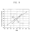
- Figure 9 is a graph of an experimental result of a noise compared to the same air flowing amount.
- the line “a” represents an experimental value obtained by adapting an axial flow fan according to the present invention
- the line “b” represents an experimental value obtained by adapting a conventional axial flow fan.
- the axial flow fan according to the present invention has a good air flowing efficiency based on an enhanced static pressure efficiency( n s).
- the power consumption is decreased by about 5W compared to the same air flowing amount between the present invention and the conventional art.
- the noise is decreased by about 1dB(A) compared to the same air flowing amount.
- the case that the diameter FD of the fan was smaller than 380mm was explained.
- Rt is fixed at 190mm for the portion in which the diameter FD of the fan is 380mm for thereby computing "r" and setting the design factors.
- the design factors of the fan are determined based on an extrapolation method.
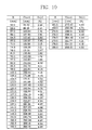
- Figure 10 illustrates a table illustrating the radius of the fan blade of the axial flow fan according to the present invention and a variation of a maximum camber ratio based on a variation of the chord length.
- the values in the table are used as basic values when designing the fan.
- the shape of the blade is changed by varying the fan design factors such as the area of the blade, and the chord length, so that it is possible to generate an enough amount of air flow for a heat exchanging operation and decrease a power consumption and noise of the motor for thereby implementing a high efficiency of the fan.
Landscapes
- Engineering & Computer Science (AREA)
- Mechanical Engineering (AREA)
- General Engineering & Computer Science (AREA)
- Chemical & Material Sciences (AREA)
- Combustion & Propulsion (AREA)
- Structures Of Non-Positive Displacement Pumps (AREA)
Applications Claiming Priority (4)
| Application Number | Priority Date | Filing Date | Title |
|---|---|---|---|
| KR1019990037837A KR100339556B1 (ko) | 1999-09-07 | 1999-09-07 | 에어콘용 실외기의 축류팬 |
| KR9937837 | 1999-09-07 | ||
| KR1019990040416A KR100339558B1 (ko) | 1999-09-20 | 1999-09-20 | 공기조화기용 축류팬 |
| KR9940416 | 1999-09-20 |
Publications (3)
| Publication Number | Publication Date |
|---|---|
| EP1083391A2 true EP1083391A2 (de) | 2001-03-14 |
| EP1083391A3 EP1083391A3 (de) | 2003-01-08 |
| EP1083391B1 EP1083391B1 (de) | 2006-12-20 |
Family
ID=26636105
Family Applications (1)
| Application Number | Title | Priority Date | Filing Date |
|---|---|---|---|
| EP99125720A Expired - Lifetime EP1083391B1 (de) | 1999-09-07 | 1999-12-23 | Axiallüfter für Klimaanlage |
Country Status (6)
| Country | Link |
|---|---|
| US (1) | US6325597B1 (de) |
| EP (1) | EP1083391B1 (de) |
| JP (1) | JP3284119B2 (de) |
| CN (1) | CN1208554C (de) |
| DE (1) | DE69934489T2 (de) |
| ES (1) | ES2279596T3 (de) |
Cited By (5)
| Publication number | Priority date | Publication date | Assignee | Title |
|---|---|---|---|---|
| DE20214833U1 (de) * | 2002-09-24 | 2003-11-06 | Meltem Wärmerückgewinnung GmbH & Co. KG, 82239 Alling | Luftaustauschsystem für die Belüftung wenigstens eines Raums eines Gebäudes |
| EP1455095A1 (de) * | 2003-03-05 | 2004-09-08 | Halla Climate Control Corporation | Axiallüfter |
| EP3018359A1 (de) * | 2014-11-07 | 2016-05-11 | Valeo Systemes Thermiques | Fahrzeuggebläse mit optimierten lüfterflügeln für hohen durchfluss |
| CN111692126A (zh) * | 2019-03-15 | 2020-09-22 | 爱三工业株式会社 | 离心泵 |
| EP4212737A4 (de) * | 2020-09-29 | 2024-03-20 | Daikin Industries, Ltd. | Propellerlüfter |
Families Citing this family (24)
| Publication number | Priority date | Publication date | Assignee | Title |
|---|---|---|---|---|
| US20040258531A1 (en) * | 2000-04-21 | 2004-12-23 | Ling-Zhong Zeng | Fan blade |
| US6814545B2 (en) * | 2000-04-21 | 2004-11-09 | Revcor, Inc. | Fan blade |
| US6712584B2 (en) * | 2000-04-21 | 2004-03-30 | Revcor, Inc. | Fan blade |
| KR100382914B1 (ko) * | 2000-07-27 | 2003-05-09 | 엘지전자 주식회사 | 축류팬 |
| ITMI20012169A1 (it) * | 2001-10-18 | 2003-04-18 | Nuovo Pignone Spa | Palettatura statorica di canali di ritorno per stadi centrifughi bidimensionali di un compressore centrifugo multistadio ad efficienza migli |
| US6672839B2 (en) * | 2001-11-16 | 2004-01-06 | Hp Intellectual Corp. | Fan wheel |
| KR100852950B1 (ko) * | 2002-05-29 | 2008-08-19 | 한라공조주식회사 | 축류팬의 블레이드 구조 |
| US6942457B2 (en) * | 2002-11-27 | 2005-09-13 | Revcor, Inc. | Fan assembly and method |
| KR100484828B1 (ko) * | 2002-11-27 | 2005-04-22 | 엘지전자 주식회사 | 냉장고의 냉기순환용 축류팬 |
| KR100641111B1 (ko) * | 2004-06-02 | 2006-11-02 | 엘지전자 주식회사 | 냉각팬 |
| JP4797392B2 (ja) * | 2005-02-15 | 2011-10-19 | パナソニック株式会社 | 送風装置 |
| CN1904492B (zh) * | 2005-07-30 | 2010-10-06 | 乐金电子(天津)电器有限公司 | 顶棚式空调器及顶棚式空调器的流路结构 |
| US20070122287A1 (en) * | 2005-11-29 | 2007-05-31 | Pennington Donald R | Fan blade assembly |
| JP4967334B2 (ja) * | 2005-12-22 | 2012-07-04 | パナソニック株式会社 | 送風装置 |
| JP2007107530A (ja) * | 2006-11-16 | 2007-04-26 | Toshiba Kyaria Kk | 軸流ファン |
| US20120134794A1 (en) * | 2009-08-25 | 2012-05-31 | Mitsubishi Electric Corporation | Fan and air-conditioning apparatus provided with fan |
| JP5540674B2 (ja) * | 2009-12-07 | 2014-07-02 | パナソニック株式会社 | 送風装置 |
| KR20120076039A (ko) * | 2010-12-29 | 2012-07-09 | 엘지전자 주식회사 | 축류팬 및 이를 포함하는 공기조화기의 실외기 |
| JP5697465B2 (ja) * | 2011-01-25 | 2015-04-08 | シャープ株式会社 | プロペラファン、成型用金型および流体送り装置 |
| USD680213S1 (en) * | 2011-03-28 | 2013-04-16 | Spal Automotive S.R.L. | Ventilator blade |
| CN104061187A (zh) * | 2014-06-30 | 2014-09-24 | 珠海格力电器股份有限公司 | 一种轴流风叶、轴流风机及空调机 |
| JP7389572B2 (ja) * | 2019-06-19 | 2023-11-30 | Ntn株式会社 | 雰囲気撹拌ファン及び熱処理炉 |
| US11999466B2 (en) * | 2019-11-14 | 2024-06-04 | Skydio, Inc. | Ultra-wide-chord propeller |
| US11428235B2 (en) * | 2020-05-15 | 2022-08-30 | Quanta Computer Inc. | Fan module and motor |
Family Cites Families (8)
| Publication number | Priority date | Publication date | Assignee | Title |
|---|---|---|---|---|
| JPH0772559B2 (ja) * | 1988-12-26 | 1995-08-02 | 株式会社東芝 | 軸流ファン構造 |
| JP3082378B2 (ja) * | 1991-12-20 | 2000-08-28 | 株式会社デンソー | 送風ファン |
| US5588804A (en) * | 1994-11-18 | 1996-12-31 | Itt Automotive Electrical Systems, Inc. | High-lift airfoil with bulbous leading edge |
| US5961289A (en) * | 1995-11-22 | 1999-10-05 | Deutsche Forshungsanstalt Fur Luft-Und Raumfahrt E.V. | Cooling axial flow fan with reduced noise levels caused by swept laminar and/or asymmetrically staggered blades |
| JPH09219850A (ja) * | 1996-02-14 | 1997-08-19 | Kyocera Corp | テレビ会議システムのカメラチルト調整装置 |
| JP3050144B2 (ja) * | 1996-11-12 | 2000-06-12 | ダイキン工業株式会社 | 軸流ファン |
| JP3684522B2 (ja) * | 1997-08-22 | 2005-08-17 | 靖正 山口 | ガラス越しに撮像する電子カメラ |
| US6116856A (en) * | 1998-09-18 | 2000-09-12 | Patterson Technique, Inc. | Bi-directional fan having asymmetric, reversible blades |
-
1999
- 1999-12-23 EP EP99125720A patent/EP1083391B1/de not_active Expired - Lifetime
- 1999-12-23 DE DE69934489T patent/DE69934489T2/de not_active Expired - Lifetime
- 1999-12-23 ES ES99125720T patent/ES2279596T3/es not_active Expired - Lifetime
- 1999-12-30 US US09/475,236 patent/US6325597B1/en not_active Expired - Lifetime
-
2000
- 2000-01-05 JP JP2000005262A patent/JP3284119B2/ja not_active Expired - Fee Related
- 2000-02-25 CN CN00102658.5A patent/CN1208554C/zh not_active Expired - Fee Related
Cited By (7)
| Publication number | Priority date | Publication date | Assignee | Title |
|---|---|---|---|---|
| DE20214833U1 (de) * | 2002-09-24 | 2003-11-06 | Meltem Wärmerückgewinnung GmbH & Co. KG, 82239 Alling | Luftaustauschsystem für die Belüftung wenigstens eines Raums eines Gebäudes |
| EP1455095A1 (de) * | 2003-03-05 | 2004-09-08 | Halla Climate Control Corporation | Axiallüfter |
| US7044712B2 (en) | 2003-03-05 | 2006-05-16 | Halla Climate Control Corporation | Axial-flow fan |
| EP3018359A1 (de) * | 2014-11-07 | 2016-05-11 | Valeo Systemes Thermiques | Fahrzeuggebläse mit optimierten lüfterflügeln für hohen durchfluss |
| FR3028299A1 (fr) * | 2014-11-07 | 2016-05-13 | Valeo Systemes Thermiques | Ventilateur pour automobile a pales optimisees pour les forts debits |
| CN111692126A (zh) * | 2019-03-15 | 2020-09-22 | 爱三工业株式会社 | 离心泵 |
| EP4212737A4 (de) * | 2020-09-29 | 2024-03-20 | Daikin Industries, Ltd. | Propellerlüfter |
Also Published As
| Publication number | Publication date |
|---|---|
| EP1083391A3 (de) | 2003-01-08 |
| DE69934489D1 (de) | 2007-02-01 |
| JP3284119B2 (ja) | 2002-05-20 |
| CN1287226A (zh) | 2001-03-14 |
| EP1083391B1 (de) | 2006-12-20 |
| JP2001082387A (ja) | 2001-03-27 |
| CN1208554C (zh) | 2005-06-29 |
| DE69934489T2 (de) | 2007-04-26 |
| ES2279596T3 (es) | 2007-08-16 |
| US6325597B1 (en) | 2001-12-04 |
Similar Documents
| Publication | Publication Date | Title |
|---|---|---|
| EP1083391A2 (de) | Axiallüfter für Klimaanlage | |
| EP2192354B1 (de) | Innenraumeinheit für eine Klimaanlage | |
| EP2447542B1 (de) | Klimaanlage mit Außeneinheit | |
| KR20140136180A (ko) | 프로펠러 팬 및 이를 구비하는 공기 조화기 | |
| KR20110085646A (ko) | 송풍장치 및 이를 구비하는 실외기 | |
| JP5295321B2 (ja) | 送風機、室外機及び冷凍サイクル装置 | |
| WO2012035577A1 (ja) | 室外ユニットの送風機、室外ユニット及び冷凍サイクル装置 | |
| US6863500B2 (en) | Blast fan | |
| JP5791276B2 (ja) | 送風機、室外ユニット及び冷凍サイクル装置 | |
| US7206724B2 (en) | Method for designing a blower wheel scroll cage | |
| KR19990066016A (ko) | 창문형 공기조화기의 덕트 | |
| CN215762421U (zh) | 一种离心风叶、风机及包含其的空调系统 | |
| JP2978150B2 (ja) | エアコンの室内機 | |
| JP6363033B2 (ja) | 空気調和機の室内機およびこれを備えた空気調和機 | |
| KR100339558B1 (ko) | 공기조화기용 축류팬 | |
| CN112283806B (zh) | 空调器 | |
| WO2015063850A1 (ja) | 貫流ファン及び空気調和機 | |
| JP3588327B2 (ja) | 窓型エアコンの送風ファンアセンブリ | |
| CN113550930A (zh) | 一种离心风叶、风机及包含其的空调系统 | |
| CN221035994U (zh) | 一种空调室外机及空调器 | |
| US12566003B2 (en) | Outdoor unit of air conditioner | |
| CN221973899U (zh) | 离心风扇及空气处理装置 | |
| CN220892415U (zh) | 一种空调室外机及空调器 | |
| KR100339556B1 (ko) | 에어콘용 실외기의 축류팬 | |
| JP7378505B2 (ja) | 遠心送風機及びそれを備えた空気調和機 |
Legal Events
| Date | Code | Title | Description |
|---|---|---|---|
| PUAI | Public reference made under article 153(3) epc to a published international application that has entered the european phase |
Free format text: ORIGINAL CODE: 0009012 |
|
| AK | Designated contracting states |
Kind code of ref document: A2 Designated state(s): AT BE CH CY DE DK ES FI FR GB GR IE IT LI LU MC NL PT SE |
|
| AX | Request for extension of the european patent |
Free format text: AL;LT;LV;MK;RO;SI |
|
| PUAL | Search report despatched |
Free format text: ORIGINAL CODE: 0009013 |
|
| AK | Designated contracting states |
Kind code of ref document: A3 Designated state(s): AT BE CH CY DE DK ES FI FR GB GR IE IT LI LU MC NL PT SE |
|
| AX | Request for extension of the european patent |
Free format text: AL;LT;LV;MK;RO;SI |
|
| RIC1 | Information provided on ipc code assigned before grant |
Free format text: 7F 24F 7/007 A, 7F 04D 29/38 B |
|
| 17P | Request for examination filed |
Effective date: 20030220 |
|
| AKX | Designation fees paid |
Designated state(s): DE ES IT |
|
| 17Q | First examination report despatched |
Effective date: 20040407 |
|
| GRAP | Despatch of communication of intention to grant a patent |
Free format text: ORIGINAL CODE: EPIDOSNIGR1 |
|
| GRAS | Grant fee paid |
Free format text: ORIGINAL CODE: EPIDOSNIGR3 |
|
| GRAA | (expected) grant |
Free format text: ORIGINAL CODE: 0009210 |
|
| AK | Designated contracting states |
Kind code of ref document: B1 Designated state(s): DE ES IT |
|
| REF | Corresponds to: |
Ref document number: 69934489 Country of ref document: DE Date of ref document: 20070201 Kind code of ref document: P |
|
| REG | Reference to a national code |
Ref country code: ES Ref legal event code: FG2A Ref document number: 2279596 Country of ref document: ES Kind code of ref document: T3 |
|
| PLBE | No opposition filed within time limit |
Free format text: ORIGINAL CODE: 0009261 |
|
| STAA | Information on the status of an ep patent application or granted ep patent |
Free format text: STATUS: NO OPPOSITION FILED WITHIN TIME LIMIT |
|
| 26N | No opposition filed |
Effective date: 20070921 |
|
| PGFP | Annual fee paid to national office [announced via postgrant information from national office to epo] |
Ref country code: DE Payment date: 20101215 Year of fee payment: 12 |
|
| PGFP | Annual fee paid to national office [announced via postgrant information from national office to epo] |
Ref country code: IT Payment date: 20110920 Year of fee payment: 13 |
|
| PGFP | Annual fee paid to national office [announced via postgrant information from national office to epo] |
Ref country code: ES Payment date: 20111014 Year of fee payment: 13 |
|
| REG | Reference to a national code |
Ref country code: DE Ref legal event code: R119 Ref document number: 69934489 Country of ref document: DE Effective date: 20130702 |
|
| PG25 | Lapsed in a contracting state [announced via postgrant information from national office to epo] |
Ref country code: DE Free format text: LAPSE BECAUSE OF NON-PAYMENT OF DUE FEES Effective date: 20130702 |
|
| PG25 | Lapsed in a contracting state [announced via postgrant information from national office to epo] |
Ref country code: IT Free format text: LAPSE BECAUSE OF NON-PAYMENT OF DUE FEES Effective date: 20121223 |
|
| REG | Reference to a national code |
Ref country code: ES Ref legal event code: FD2A Effective date: 20140307 |
|
| PG25 | Lapsed in a contracting state [announced via postgrant information from national office to epo] |
Ref country code: ES Free format text: LAPSE BECAUSE OF NON-PAYMENT OF DUE FEES Effective date: 20121224 |