EP1083396A2 - Kiln for firing industrial articles - Google Patents
Kiln for firing industrial articles Download PDFInfo
- Publication number
- EP1083396A2 EP1083396A2 EP00119175A EP00119175A EP1083396A2 EP 1083396 A2 EP1083396 A2 EP 1083396A2 EP 00119175 A EP00119175 A EP 00119175A EP 00119175 A EP00119175 A EP 00119175A EP 1083396 A2 EP1083396 A2 EP 1083396A2
- Authority
- EP
- European Patent Office
- Prior art keywords
- burners
- firing chamber
- kiln according
- row
- kiln
- Prior art date
- Legal status (The legal status is an assumption and is not a legal conclusion. Google has not performed a legal analysis and makes no representation as to the accuracy of the status listed.)
- Granted
Links
Images


Classifications
-
- F—MECHANICAL ENGINEERING; LIGHTING; HEATING; WEAPONS; BLASTING
- F27—FURNACES; KILNS; OVENS; RETORTS
- F27B—FURNACES, KILNS, OVENS OR RETORTS IN GENERAL; OPEN SINTERING OR LIKE APPARATUS
- F27B9/00—Furnaces through which the charge is moved mechanically, e.g. of tunnel type; Similar furnaces in which the charge moves by gravity
- F27B9/30—Details, accessories or equipment specially adapted for furnaces of these types
- F27B9/32—Casings
-
- F—MECHANICAL ENGINEERING; LIGHTING; HEATING; WEAPONS; BLASTING
- F27—FURNACES; KILNS; OVENS; RETORTS
- F27B—FURNACES, KILNS, OVENS OR RETORTS IN GENERAL; OPEN SINTERING OR LIKE APPARATUS
- F27B9/00—Furnaces through which the charge is moved mechanically, e.g. of tunnel type; Similar furnaces in which the charge moves by gravity
- F27B9/30—Details, accessories or equipment specially adapted for furnaces of these types
-
- F—MECHANICAL ENGINEERING; LIGHTING; HEATING; WEAPONS; BLASTING
- F27—FURNACES; KILNS; OVENS; RETORTS
- F27B—FURNACES, KILNS, OVENS OR RETORTS IN GENERAL; OPEN SINTERING OR LIKE APPARATUS
- F27B9/00—Furnaces through which the charge is moved mechanically, e.g. of tunnel type; Similar furnaces in which the charge moves by gravity
- F27B9/30—Details, accessories or equipment specially adapted for furnaces of these types
- F27B9/36—Arrangements of heating devices
-
- F—MECHANICAL ENGINEERING; LIGHTING; HEATING; WEAPONS; BLASTING
- F27—FURNACES; KILNS; OVENS; RETORTS
- F27D—DETAILS OR ACCESSORIES OF FURNACES, KILNS, OVENS OR RETORTS, IN SO FAR AS THEY ARE OF KINDS OCCURRING IN MORE THAN ONE KIND OF FURNACE
- F27D1/00—Casings; Linings; Walls; Roofs
- F27D1/10—Monolithic linings; Supports therefor
-
- F—MECHANICAL ENGINEERING; LIGHTING; HEATING; WEAPONS; BLASTING
- F27—FURNACES; KILNS; OVENS; RETORTS
- F27B—FURNACES, KILNS, OVENS OR RETORTS IN GENERAL; OPEN SINTERING OR LIKE APPARATUS
- F27B9/00—Furnaces through which the charge is moved mechanically, e.g. of tunnel type; Similar furnaces in which the charge moves by gravity
- F27B9/30—Details, accessories or equipment specially adapted for furnaces of these types
- F27B9/36—Arrangements of heating devices
- F27B2009/3638—Heaters located above and under the track
Definitions
- the invention relates to a kiln for firing industrial articles, particularly a kiln for firing ceramic articles.
- kilns for firing ceramic articles comprising art external structure defining a firing chamber lined with refractory material, through which ceramic articles, arranged in transversal rows, are advanced, for example on planes of motorized rollers.
- burners are arranged having heads projecting into the firing chamber in which the combustion of the fuel feeding the burners takes place for providing heat necessary for firing the ceramic articles.
- the kiln has a modular arrangement, i.e.
- the firing chamber has a substantially rectangular cross section. This shape of the firing chamber, the arrangement and number of burners in each section of the kiln causes a non-uniform distribution of temperature in the firing chamber, so generating temperature stratification zones, which causes non-uniform firing of the products, possible damages due to different firing temperature for the product of a same row, greater consumption of fuel.
- the present invention is intended to provide a kiln for firing industrial articles, particularly ceramic articles, in which the distribution of temperature within the firing chamber is as uniform as possible.
- a kiln for firing industrial articles comprising a structure internally defining a firing chamber inside which said articles are advanced on advancing means, refractory means for lining said firing chamber, a plurality of burners arranged along side walls of said firing chamber, characterized in that said firing chamber comprises anti-stratification means suitable for preventing temperature stratification zones from forming inside said firing chamber.
- a distribution of temperature as uniform as possible may be obtained in the firing chamber, which allows a better and more regular firing of the articles and smaller consumption of fuel to be obtained.
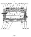
- the kiln 1 comprises a structure 2 in which a chamber 3 for firing industrial articles, for example ceramic articles, is defined.
- the chamber 3 is defined laterally by side walls 4, 4a, each provided with refractory lining 5, 5a, at the top by a vault also provided with a refractory lining 7, and at the bottom by a floor 8 made of refractory material.
- the refractory lining 7 is fixed to the vault of the kiln by hook means 12, for example brackets.
- a plurality of transversal motorized rollers 9 are arranged in the chamber 3, said rollers defining an advancing plane for the articles to be fired in the chamber 3.
- Two rows of burners 10, 11 are arranged on the side walls 4 of the chamber 3, a first row being arranged on the wall 4a, below the plane of the roller 9 and a second row of burners 11 being arranged on the wall 4, opposite to the wall 4a, above the plane of the roller 9.
- the side end portions 13 and 14 of the refractory lining 7 of the vault 6 of the kiln are tilted downward, toward the side walls 4 and the side end portions 15 and 16 of the floor 8 of the kiln are tilted upward toward the side walls 4.
- the section of the firing chamber 3 comprises a central part having substantially even height and two side parts having height progressively decreasing toward the side walls 4. This shape promotes a circulation of air and combustion fumes produced by the burners 10 and 11, preventing air and fumes stagnation zones from being created and so ensuring a remarkably better temperature uniformity, with respect to the kilns of the state of art.
- the temperature uniformity is further improved since the height of the firing chamber 3 progressively decreases along the advancing direction of the articles to be fired, so promoting a flow of the air and of the fumes in said direction, which contributes to a further improvement of the temperature distribution.
- the height decrease of the firing chamber 3 may be, for example, equal to 1%, i.e. about 1 centimetre per linear metre. Said height decrease may be obtained shaping the vault 6 tilted downward along the advancing direction of the articles to be fired.
- the floor 8 of the chamber 3 may be tilted upward along the advancing direction of the articles to be fired.
- the kiln 1 comprises a row of modular units 17, 17a, 17b, 17c, having substantially equal length, one of which is shown in Figure 2, while Figure 3 shows three modular units arranged in a sequence.
- the modular units 17, 17a, 17b, 17c are coordinated so as to obtain the height decrease of the firing chamber 3 along the whole length of the kiln 1.
- the tilt of the vault 6 and of the floor 8 are shown more greater than they are in reality, only for emphasizing purpose.
- Each modular unit 17, 17a, 17b, 17c is provided, at each side, with two groups each comprising three burners, a first group of three burners 10 being arranged below the plane of the rollers 9and a second group of three burners 11 being arranged above the plane of the rollers 9.
- each modular unit having the same length of a modular unit of prior art kilns comprises a further burner for each group, that is, on the whole, four further burners for each modular unit 17, 17a, 17b, 17c.
- a better heat distribution and smaller fuel consumption are obtained inside the firing chamber 3.
- the burners may be operated at a lower combustion temperature, i.e. a temperature closer to the requested firing temperature of the articles, which allows the fuel consumption of each burner to be reduced, the temperature obtained in the firing chamber 3 being the same. Furthermore, the reduction of the combustion temperature of the burners reduces the thermal shocks of the lining of the kiln 1 so increasing the service life of the kiln.
- the groups of burners 10, 11 may also comprise a different number of burners, for example the group of burners 10 may comprise three burners, while the group of burners 11 may comprise two burners, or vice versa.
- the average distance between the burners 10, 11 of each group of burners is within about 400 mm and about 850 mm depending on the length of each modular unit 17, 17a, 17b, 17c and is chosen so as to optimize the heat distribution inside each of said modular unities 17, 17a, 17b, 17c.
Landscapes
- Engineering & Computer Science (AREA)
- Mechanical Engineering (AREA)
- General Engineering & Computer Science (AREA)
- Vertical, Hearth, Or Arc Furnaces (AREA)
- Tunnel Furnaces (AREA)
- General Preparation And Processing Of Foods (AREA)
- Crucibles And Fluidized-Bed Furnaces (AREA)
- Constitution Of High-Frequency Heating (AREA)
- Furnace Details (AREA)
Abstract
Description
Claims (17)
- Kiln (1) for firing industrial articles, particularly ceramic articles, comprising a structure (2) internally defining a firing chamber (3) inside which said articles are advanced on advancing means (9), refractory means (5, 6, 7, 8) for lining said firing chamber (3), a plurality of burners (10, 11) arranged along side walls (4, 4a) of said firing chamber (3), characterized in that said firing chamber (3) comprises anti-stratification means (13, 14, 15, 16) suitable for preventing temperature stratification zones from forming inside said firing chamber (3).
- Kiln according to claim 1, wherein said anti-stratification means (13, 14, 15, 16) comprises side end portions (13, 14) of the refractory lining (7) of the vault (6) of the kiln (1), each of said side end portions (13, 14) being tilted downward toward the corresponding side wall (4, 4a) of said firing chamber (3).
- Kiln according to claim 1, or 2, wherein said anti-stratification means (13, 14, 15, 16) comprises side end portions (15, 16) of the floor (8) of the kiln (1), each of said side end portions (15, 16) being tilted upward toward the corresponding side wall (4, 4a) of said firing chamber (3).
- Kiln according to any one of the preceding claims, wherein said firing chamber (3) has height progressively decreasing along the advancing direction of said articles.
- Kiln according to claim 4, wherein said height of the firing chamber (3) decreases of about 1 cm per linear metre along said advancing direction.
- Kiln according to claim 4, or 5, wherein said vault (6) is tilted downward along said advancing direction.
- Kiln according to any one of claims 4 to 6, wherein said floor (8) is tilted upward along said advancing direction.
- Kiln according to any one of the preceding claims, comprising a plurality of modular units (17, 17a, 17b, 17c), each of said modular units (17, 17a, 17b, 17c) having substantially the same length.
- Kiln according to claim 8, wherein said modular units (17, 17a, 17b, 17c) are so co-ordinated as to obtain said progressively decreasing height.
- Kiln according to claim 8, or 9, wherein each of said modular units (17, 17a, 17b, 17c) comprises a first group (10) of said burners (10, 11) arranged on a side wall (4a) of said firing chamber (3), said first group (10) of burners (10, 11) comprising more than four burners.
- Kiln according to claim 10, wherein the burners (10, 11) of said first group (10) of burners are aligned in two rows staggered with respect to each other along said side wall (4a) of said firing chamber (3), said two rows comprising a first row arranged below said advancing means (9) and a second row arranged above said advancing means (9), one of said two rows comprising at least three burners (10, 11).
- Kiln according to claim 21, wherein said first row and said second row comprise the same number of burners (10, 11).
- Kiln according to claim 11, wherein the number of burners (10, 11) of said first row is different from the number of burners (10, 11) of said second row.
- Kiln according to any one of claims 10 to 13, wherein each of said modular unities (17, 17a, 17b, 17c) comprises a second group (11) of said burners (10, 11) arranged on a wall (4) opposite to said wall (4a) of said firing chamber (3), said second group (11) of burners (10, 11) comprising more than four burners (10, 11.
- Kiln according to claim 14, wherein the burners (10, 11) of said second group (11) of burners (10, 11) are aligned in two further rows staggered with respect to each other along said Side wall (4) of said firing chamber (3), said two further rows comprising a further first row arranged below said advancing means (9) and a further second row arranged above said advancing means (9), one of said two further rows comprising at least three burners (10, 11).
- Kiln according to claim 15, wherein said further first row and said further second row comprise the same number of burners (10, 11).
- Kiln according to claim 15, wherein the number of burners (10, 11) of said further first row is different from the number of burners (10, 11) of said further second row.
Applications Claiming Priority (2)
| Application Number | Priority Date | Filing Date | Title |
|---|---|---|---|
| ITMO990180 | 1999-09-07 | ||
| IT1999MO000180A IT1310820B1 (en) | 1999-09-07 | 1999-09-07 | OVEN FOR COOKING INDUSTRIAL MANUFACTURES. |
Publications (3)
| Publication Number | Publication Date |
|---|---|
| EP1083396A2 true EP1083396A2 (en) | 2001-03-14 |
| EP1083396A3 EP1083396A3 (en) | 2001-08-01 |
| EP1083396B1 EP1083396B1 (en) | 2004-11-24 |
Family
ID=11387048
Family Applications (1)
| Application Number | Title | Priority Date | Filing Date |
|---|---|---|---|
| EP00119175A Expired - Lifetime EP1083396B1 (en) | 1999-09-07 | 2000-09-05 | Kiln for firing industrial articles |
Country Status (6)
| Country | Link |
|---|---|
| EP (1) | EP1083396B1 (en) |
| AT (1) | ATE283465T1 (en) |
| DE (1) | DE60016123D1 (en) |
| ES (1) | ES2232364T3 (en) |
| IT (1) | IT1310820B1 (en) |
| PT (1) | PT1083396E (en) |
Cited By (2)
| Publication number | Priority date | Publication date | Assignee | Title |
|---|---|---|---|---|
| CN102147191A (en) * | 2010-02-09 | 2011-08-10 | 中冶长天国际工程有限责任公司 | Furnace hood and rotary hearth furnace |
| CN101629784B (en) * | 2008-07-15 | 2012-04-25 | 广东萨米特陶瓷有限公司 | Wide roller kiln for firing porcelain tile |
Family Cites Families (3)
| Publication number | Priority date | Publication date | Assignee | Title |
|---|---|---|---|---|
| DE568882C (en) * | 1933-01-25 | Philipp Rack | Annealing furnace with uninterrupted conveyance of the incandescent material on conveyor rollers | |
| DE942692C (en) * | 1951-09-25 | 1956-05-03 | Stahl & Droste Industrieofenba | Conveyor device for continuously operated annealing or heating furnace and process for operating the same |
| DE1143840B (en) * | 1956-02-08 | 1963-02-21 | Iaofuia Ofenbau Union G M B H | Roller hearth for a roller hearth furnace |
-
1999
- 1999-09-07 IT IT1999MO000180A patent/IT1310820B1/en active
-
2000
- 2000-09-05 AT AT00119175T patent/ATE283465T1/en not_active IP Right Cessation
- 2000-09-05 EP EP00119175A patent/EP1083396B1/en not_active Expired - Lifetime
- 2000-09-05 DE DE60016123T patent/DE60016123D1/en not_active Expired - Lifetime
- 2000-09-05 PT PT00119175T patent/PT1083396E/en unknown
- 2000-09-05 ES ES00119175T patent/ES2232364T3/en not_active Expired - Lifetime
Cited By (2)
| Publication number | Priority date | Publication date | Assignee | Title |
|---|---|---|---|---|
| CN101629784B (en) * | 2008-07-15 | 2012-04-25 | 广东萨米特陶瓷有限公司 | Wide roller kiln for firing porcelain tile |
| CN102147191A (en) * | 2010-02-09 | 2011-08-10 | 中冶长天国际工程有限责任公司 | Furnace hood and rotary hearth furnace |
Also Published As
| Publication number | Publication date |
|---|---|
| EP1083396B1 (en) | 2004-11-24 |
| ATE283465T1 (en) | 2004-12-15 |
| ITMO990180A1 (en) | 2001-03-07 |
| ITMO990180A0 (en) | 1999-09-07 |
| PT1083396E (en) | 2005-03-31 |
| EP1083396A3 (en) | 2001-08-01 |
| ES2232364T3 (en) | 2005-06-01 |
| DE60016123D1 (en) | 2004-12-30 |
| IT1310820B1 (en) | 2002-02-22 |
Similar Documents
| Publication | Publication Date | Title |
|---|---|---|
| US4025298A (en) | Walking beam furnace for round bar and the like | |
| EP1083396B1 (en) | Kiln for firing industrial articles | |
| EP2546592B1 (en) | Device for transferring a metallurgical material | |
| US3820946A (en) | Longitudinally fired walking beam furnace | |
| KR20100105880A (en) | Improved burning system | |
| US20150130120A1 (en) | Device for transferring a metallurgical material | |
| CN101454632B (en) | Reheating furnace with an improved discharge zone | |
| US2099967A (en) | Muffle and like furnace | |
| CN112146435B (en) | Furnace top structure of light roller furnace | |
| US2839285A (en) | Heat treatment furnaces | |
| EP0504117A1 (en) | A tempering furnace, in particular for sheets of glass and similar | |
| CA2527643A1 (en) | Cooling and support systems for furnace roofs | |
| US3354293A (en) | Electric furnace for ceramics | |
| US409489A (en) | Kiln for the manufacture of carbons | |
| JP4378549B2 (en) | Firing equipment | |
| US5704783A (en) | Walking hearth furnace | |
| US3736119A (en) | Glass furnace lip-tile | |
| WO2015015263A2 (en) | A radiating heating module for continuous-cycle firing kilns of ceramic products | |
| JPH0642877A (en) | Beam kiln | |
| US680997A (en) | Heating-furnace. | |
| CN220153237U (en) | Preheating device for tunnel kiln car | |
| US2224460A (en) | Furnace | |
| US2504484A (en) | Multiple tunnel kiln | |
| EP0208920A1 (en) | An apparatus for firing ceramic materials particularly useful for firing glazed tiles | |
| JP7117902B2 (en) | heating furnace |
Legal Events
| Date | Code | Title | Description |
|---|---|---|---|
| PUAI | Public reference made under article 153(3) epc to a published international application that has entered the european phase |
Free format text: ORIGINAL CODE: 0009012 |
|
| AK | Designated contracting states |
Kind code of ref document: A2 Designated state(s): AT BE CH CY DE DK ES FI FR GB GR IE IT LI LU MC NL PT SE |
|
| AX | Request for extension of the european patent |
Free format text: AL;LT;LV;MK;RO;SI |
|
| PUAL | Search report despatched |
Free format text: ORIGINAL CODE: 0009013 |
|
| AK | Designated contracting states |
Kind code of ref document: A3 Designated state(s): AT BE CH CY DE DK ES FI FR GB GR IE IT LI LU MC NL PT SE |
|
| AX | Request for extension of the european patent |
Free format text: AL;LT;LV;MK;RO;SI |
|
| 17P | Request for examination filed |
Effective date: 20011022 |
|
| AKX | Designation fees paid |
Free format text: AT BE CH CY DE DK ES FI FR GB GR IE IT LI LU MC NL PT SE |
|
| 17Q | First examination report despatched |
Effective date: 20021120 |
|
| GRAP | Despatch of communication of intention to grant a patent |
Free format text: ORIGINAL CODE: EPIDOSNIGR1 |
|
| GRAS | Grant fee paid |
Free format text: ORIGINAL CODE: EPIDOSNIGR3 |
|
| GRAA | (expected) grant |
Free format text: ORIGINAL CODE: 0009210 |
|
| AK | Designated contracting states |
Kind code of ref document: B1 Designated state(s): AT BE CH CY DE DK ES FI FR GB GR IE IT LI LU MC NL PT SE |
|
| PG25 | Lapsed in a contracting state [announced via postgrant information from national office to epo] |
Ref country code: CH Free format text: LAPSE BECAUSE OF FAILURE TO SUBMIT A TRANSLATION OF THE DESCRIPTION OR TO PAY THE FEE WITHIN THE PRESCRIBED TIME-LIMIT Effective date: 20041124 Ref country code: NL Free format text: LAPSE BECAUSE OF FAILURE TO SUBMIT A TRANSLATION OF THE DESCRIPTION OR TO PAY THE FEE WITHIN THE PRESCRIBED TIME-LIMIT Effective date: 20041124 Ref country code: BE Free format text: LAPSE BECAUSE OF FAILURE TO SUBMIT A TRANSLATION OF THE DESCRIPTION OR TO PAY THE FEE WITHIN THE PRESCRIBED TIME-LIMIT Effective date: 20041124 Ref country code: FR Free format text: LAPSE BECAUSE OF FAILURE TO SUBMIT A TRANSLATION OF THE DESCRIPTION OR TO PAY THE FEE WITHIN THE PRESCRIBED TIME-LIMIT Effective date: 20041124 Ref country code: FI Free format text: LAPSE BECAUSE OF FAILURE TO SUBMIT A TRANSLATION OF THE DESCRIPTION OR TO PAY THE FEE WITHIN THE PRESCRIBED TIME-LIMIT Effective date: 20041124 Ref country code: AT Free format text: LAPSE BECAUSE OF FAILURE TO SUBMIT A TRANSLATION OF THE DESCRIPTION OR TO PAY THE FEE WITHIN THE PRESCRIBED TIME-LIMIT Effective date: 20041124 Ref country code: LI Free format text: LAPSE BECAUSE OF FAILURE TO SUBMIT A TRANSLATION OF THE DESCRIPTION OR TO PAY THE FEE WITHIN THE PRESCRIBED TIME-LIMIT Effective date: 20041124 |
|
| REG | Reference to a national code |
Ref country code: GB Ref legal event code: FG4D |
|
| REG | Reference to a national code |
Ref country code: CH Ref legal event code: EP |
|
| REF | Corresponds to: |
Ref document number: 60016123 Country of ref document: DE Date of ref document: 20041230 Kind code of ref document: P |
|
| REG | Reference to a national code |
Ref country code: IE Ref legal event code: FG4D |
|
| PG25 | Lapsed in a contracting state [announced via postgrant information from national office to epo] |
Ref country code: GR Free format text: LAPSE BECAUSE OF FAILURE TO SUBMIT A TRANSLATION OF THE DESCRIPTION OR TO PAY THE FEE WITHIN THE PRESCRIBED TIME-LIMIT Effective date: 20050224 Ref country code: DK Free format text: LAPSE BECAUSE OF FAILURE TO SUBMIT A TRANSLATION OF THE DESCRIPTION OR TO PAY THE FEE WITHIN THE PRESCRIBED TIME-LIMIT Effective date: 20050224 Ref country code: SE Free format text: LAPSE BECAUSE OF FAILURE TO SUBMIT A TRANSLATION OF THE DESCRIPTION OR TO PAY THE FEE WITHIN THE PRESCRIBED TIME-LIMIT Effective date: 20050224 |
|
| PG25 | Lapsed in a contracting state [announced via postgrant information from national office to epo] |
Ref country code: DE Free format text: LAPSE BECAUSE OF FAILURE TO SUBMIT A TRANSLATION OF THE DESCRIPTION OR TO PAY THE FEE WITHIN THE PRESCRIBED TIME-LIMIT Effective date: 20050225 |
|
| REG | Reference to a national code |
Ref country code: PT Ref legal event code: SC4A Free format text: AVAILABILITY OF NATIONAL TRANSLATION Effective date: 20050124 |
|
| NLV1 | Nl: lapsed or annulled due to failure to fulfill the requirements of art. 29p and 29m of the patents act | ||
| REG | Reference to a national code |
Ref country code: CH Ref legal event code: PL |
|
| REG | Reference to a national code |
Ref country code: ES Ref legal event code: FG2A Ref document number: 2232364 Country of ref document: ES Kind code of ref document: T3 |
|
| PG25 | Lapsed in a contracting state [announced via postgrant information from national office to epo] |
Ref country code: CY Free format text: LAPSE BECAUSE OF FAILURE TO SUBMIT A TRANSLATION OF THE DESCRIPTION OR TO PAY THE FEE WITHIN THE PRESCRIBED TIME-LIMIT Effective date: 20050905 Ref country code: GB Free format text: LAPSE BECAUSE OF NON-PAYMENT OF DUE FEES Effective date: 20050905 Ref country code: IT Free format text: LAPSE BECAUSE OF NON-PAYMENT OF DUE FEES Effective date: 20050905 |
|
| PG25 | Lapsed in a contracting state [announced via postgrant information from national office to epo] |
Ref country code: ES Free format text: LAPSE BECAUSE OF NON-PAYMENT OF DUE FEES Effective date: 20050906 |
|
| PG25 | Lapsed in a contracting state [announced via postgrant information from national office to epo] |
Ref country code: LU Free format text: LAPSE BECAUSE OF NON-PAYMENT OF DUE FEES Effective date: 20050930 Ref country code: MC Free format text: LAPSE BECAUSE OF NON-PAYMENT OF DUE FEES Effective date: 20050930 |
|
| PLBE | No opposition filed within time limit |
Free format text: ORIGINAL CODE: 0009261 |
|
| STAA | Information on the status of an ep patent application or granted ep patent |
Free format text: STATUS: NO OPPOSITION FILED WITHIN TIME LIMIT |
|
| 26N | No opposition filed |
Effective date: 20050825 |
|
| EN | Fr: translation not filed | ||
| GBPC | Gb: european patent ceased through non-payment of renewal fee |
Effective date: 20050905 |
|
| PG25 | Lapsed in a contracting state [announced via postgrant information from national office to epo] |
Ref country code: PT Free format text: LAPSE BECAUSE OF NON-PAYMENT OF DUE FEES Effective date: 20060605 |
|
| REG | Reference to a national code |
Ref country code: IE Ref legal event code: MM4A |
|
| REG | Reference to a national code |
Ref country code: PT Ref legal event code: MM4A Effective date: 20060605 |
|
| REG | Reference to a national code |
Ref country code: ES Ref legal event code: FD2A Effective date: 20050906 |
|
| PG25 | Lapsed in a contracting state [announced via postgrant information from national office to epo] |
Ref country code: PT Free format text: LAPSE BECAUSE OF NON-PAYMENT OF DUE FEES Effective date: 20050905 |