EP1083537A2 - Siegelgerät - Google Patents
Siegelgerät Download PDFInfo
- Publication number
- EP1083537A2 EP1083537A2 EP00307038A EP00307038A EP1083537A2 EP 1083537 A2 EP1083537 A2 EP 1083537A2 EP 00307038 A EP00307038 A EP 00307038A EP 00307038 A EP00307038 A EP 00307038A EP 1083537 A2 EP1083537 A2 EP 1083537A2
- Authority
- EP
- European Patent Office
- Prior art keywords
- filament
- connection bar
- sealing
- stopping ring
- parts
- Prior art date
- Legal status (The legal status is an assumption and is not a legal conclusion. Google has not performed a legal analysis and makes no representation as to the accuracy of the status listed.)
- Withdrawn
Links
- 238000007789 sealing Methods 0.000 title claims abstract description 72
- 230000037431 insertion Effects 0.000 claims abstract description 35
- 238000003780 insertion Methods 0.000 claims abstract description 35
- 230000013011 mating Effects 0.000 claims description 5
- 229920003002 synthetic resin Polymers 0.000 description 2
- 239000000057 synthetic resin Substances 0.000 description 2
- 239000004677 Nylon Substances 0.000 description 1
- 239000004743 Polypropylene Substances 0.000 description 1
- 238000005452 bending Methods 0.000 description 1
- 230000002427 irreversible effect Effects 0.000 description 1
- 239000000463 material Substances 0.000 description 1
- 229920001778 nylon Polymers 0.000 description 1
- 229920000728 polyester Polymers 0.000 description 1
- -1 polypropylene Polymers 0.000 description 1
- 229920001155 polypropylene Polymers 0.000 description 1
Images



Classifications
-
- G—PHYSICS
- G09—EDUCATION; CRYPTOGRAPHY; DISPLAY; ADVERTISING; SEALS
- G09F—DISPLAYING; ADVERTISING; SIGNS; LABELS OR NAME-PLATES; SEALS
- G09F3/00—Labels, tag tickets, or similar identification or indication means; Seals; Postage or like stamps
- G09F3/02—Forms or constructions
- G09F3/03—Forms or constructions of security seals
- G09F3/0305—Forms or constructions of security seals characterised by the type of seal used
- G09F3/037—Forms or constructions of security seals characterised by the type of seal used having tie-wrap sealing means
Definitions
- the present invention relates to a sealing implement for sealing by affixing a tag such as a brand label, price tag, material explanation, or handling instructions to a product such as a garment, shoes, or bag, and more particularly it relates to a sealing implement capable of performing an operation of smoothly affixing a tag when the above-noted tag is set into a special attachment apparatus (gun).
- a tag such as a brand label, price tag, material explanation, or handling instructions
- a product such as a garment, shoes, or bag
- such an implement can have a configuration formed by a filament forming a loop that is passed through a tag, an insertion head part formed on one end the filament and a socket part having an insertion hole for the purpose of passing the insertion head part, provided on the other end of the filament.
- a plurality of sealing implements are temporarily attached to two mutually parallel connection bars so as to enable removal therefrom.
- the sealing implement can be, for example, integrally formed of a synthetic resin, and in particular the filament part thereof is drawn and exhibits extremely high strength with respect to pulling tension.
- a hook acting as an engaging piece provided in proximity to the insertion hole opens, so that the neck part of the insertion head part is irreversibly held within the socket part, thereby completing the sealing, in a condition in which the label is affixed with the implement forming a loop.
- sealing implements were loaded into a special ejecting apparatus (attachment gun), a lever thereof being pulled, thereby enabling use chiefly in bundling of such items as boots, sandals, and shoes, and also in fixing of a price tag, or a tag T having instructions for use of the product to the product.
- attachment gun attachment gun
- the present invention adopts the following base technical constitution.
- the present invention is a sealing implement having a plurality of single sealing implements having a flexible filament part, an insertion head part having an appropriate engaging part provided on one end part of the filament part, and a socket part having a hole for the purpose of irreversibly inserting the insertion head part provided on the other end of the filament, the arrangement of the plurality of single sealing implements being made so that the filament parts thereof are mutually parallel and adjacent, each of the plurality of insertion head parts or a portion proximity thereto and socket parts or a portion proximity thereto being caused to be connected to separately provided connection bar parts.
- a feature of the present invention is that a filament part with a stopping ring that mates with a part of the other connection bar is mounted on at least one part of one of a connection bar, and that a grabbing piece is formed on the stopping ring.
- a sealing implement according to the present invention improves the work efficiency of the task of setting the implements into a shooting gun.
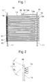
- Fig. 1 is a front view showing an embodiment of a sealing implement according to the present invention.
- Fig. 2 is a partial enlarged side view showing a connection bar used in the embodiment shown in Fig. 1.
- Fig. 3 is a partial enlarged side view showing a stopping ring used in the embodiment shown in Fig. 1.
- Fig. 4 is a plan view showing the condition of use of the embodiment shown in Fig. 1.
- Fig. 5 is a perspective view showing the condition of loading the sealing implement according to the present invention into a special shooting gun.
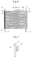
- Fig. 6 is a front view of a sealing implement showing another embodiment of the present invention.
- Fig. 7 is a partially enlarged side view showing another embodiment of a connection bar used in a sealing implement according to the present invention.
- Fig. 8 is a partial enlarged front view of a sealing implement showing another embodiment having a separately provided stopping ring.
- Fig. 1 is a front view showing an embodiment of a sealing implement according to the present invention
- Fig. 2 is a partial enlarged side view showing the same sealing implement.
- a plurality of sealing implements 10 each having a flexible filament part 12, an insertion head 13 having an appropriate engaging part, and provided on one end of the filament part 12, and a socket part 15 having an insertion hole 14 for irreversible passing of the insertion head part 13, and provided on the other end of the filament part 12 are arranged so that the filament parts 12 thereof are mutually adjacent and parallel, with each of the plurality of insertion head parts 13 or a portion proximity thereto and socket parts 15 or a portion proximity thereto, being caused to be connected to separately provided connection bar parts 11 and 11', a filament part 12a having a stopping ring 19 being mounted to a part of a connection bar 11, and a grabbing piece 20 being formed on the stopping ring 19.
- the sealing implement 10 according to the present invention is integrally formed of a synthetic resin, such as the usual Nylon, polypropylene, or polyester, such as was the case with sealing implements of the past.
- the basic configuration of the sealing implement 10 according to the present invention is substantially the same as a sealing implement of the past, and additionally has formed a filament part 12a with a stopping ring 19 on an end (top end) of the connection bar 11, and a grabbing piece 20 formed on this stopping ring 19.
- the stopping ring 19 has an inner diameter formed so as to enable insertion of the connection bar part 11.
- a protrusion 19b that engages with a cutout formed on the connection bar part 11 (refer to Fig. 3).
- the grabbing piece 20 mounted to the stopping ring 19 has the shape of a flat tongue, so as to make it easy to grab by the fingers.
- center axis line of the stopping ring 19 is formed so as to be in the perpendicular to the longitudinal direction of the filament part 12a or in parallel with a plane formed by a plurality of filaments 12 of each one of the implements, each being uniformly arranged to each other.
- the length of the filament part 12a is formed so as to be substantially 1/2 that of the filament part 12, An un-drawn filament can be used as the filament part 12a.
- a cutout 16 such as shown in Fig. 2 is formed on a corresponding position of the connection bar part 11, so that it is difficult to pull out a stopping ring 19 once it has been inserted.
- the corresponding position at which is formed the cutout 16 is ideally a position on the connection bar part 11 which is on the outside when the filament part 12 is bent in a U-shape.
- the cutout 16 is made as a V-shape having an elevation angle of 30 ° and depression angle of 45 ° , so that it has a V-shape having an angle-of 75° when the connection bar part 11 is in the vertical position.
- the cutout 16 is not restricted to this angle, and can be made any angle between 30 ° and 90° .
- An engaging part 17 is formed in the insertion hole 14 of the socket part 15, to enable engagement with an engaging part 13a having a narrowed diameter at a step on part of the insertion head part 13.
- the engaging part 17 is formed so as to protrude and be deformable into the insertion hole 14.
- the sealing implements 10 are temporarily held to the connection bars 11 so that they are mutually parallel. Therefore, after loading into an attachment gun, by merely pulling a lever 18a, it is easy for one sealing implement at a time to become separated and shot out, thereby enabling mounting of labels and the like.
- Fig. 4 is a plan view showing the condition of use of a sealing implement of the present invention.
- Fig. 5 is a perspective view showing the condition in which a sealing implement 10 according to the present invention is loaded into a special attachment apparatus (gun).
- the attachment gun 18 has formed in it a vertical groove 21 into which the connection bar parts 11 are inserted.
- the connection bar part 11 linked to a socket part 15 of the sealing implement 10 is inserted into the vertical groove 21, and the connection bar 11 linked to the insertion head part 13 is inserted into the vertical groove 22.
- a shooting pin (not shown in the drawing) is arranged in a sideways direction of the vertical groove 22, this pin being driven by the lever 18a of the shooting apparatus 18, the insertion head part 13 being separated from the linking part lla of the connection bar part 11, and pushed out and frontward, along a cylindrically shaped guide pin 24.
- connection bar part 11 The socket 15 supported by the connection bar part 11 is inserted into the vertical groove 22 is separated by a push-out belt (not shown in the drawing) from the connection bar part 11, and is pushed out and frontward one by one, along a curved socket part guide 26.
- the socket part 15 that is pushed out along the socket part guide 26 is changed by 90 ° so that there is mating with the insertion head part 13 pushed out by the push-out pin (not shown in the drawing) at the insertion hole 14.
- the inside of the socket part guide 26 is formed in the shape of a cylinder, so as to enable a change of 90 ° in direction, and to enable forward movement of the push-out belt while bending.
- the configuration is such that the timing at which the end of the push-out belt reaches the tip end of the socket part guide 26 coincides with the timing at which the push out pin reaches the end of the socket part guide 26.
- the sealing implement 10 can be used to perform continuous successive mounting of labels on products, for example.
- the center axis of the hole part 23a of the stopping ring 23 is formed so as to be in parallel with the longitudinal direction of the connection bar part 11.
- the flat surface of the grabbing piece 20 is also disposed so as to be perpendicular to the longitudinal direction of the connection bar part 11.
- Fig. 7 is an enlarged side view showing the main part of another embodiment of a connection bar part 11 used in a sealing implement according to the present invention.
- a protrusion 27 for preventing pull-off is formed near the upper end part of the connection bar part 11.
- the corresponding position at which the protrusion 27 is formed is, ideally a position on the connection bar part 11 which is on the outside when the filament part 12 is bent into a U-shape.
- Fig. 8 is a side view of the main part of a sealing implement, showing another embodiment having a separately provided stopping member.
- the sealing implement has a separately provided stopping member having stopping rings 29 and 30 enabling partial insertion of the connection bar part 11 into both ends of a filament 28 that is shorter than the separate filament part 12.
- a grabbing piece 31 is mounted on the side of the stopping ring 29 opposite the filament 28.
- the grabbing piece 31 has a flat shape so as to make it easy to grab by the fingers.
- the grabbing piece 20 used in the sealing implement according to the present invention can be a flat semicircle, and can alternately be tongue-shaped, elliptical, a sheet, or rectangular. Additionally, it is desirable that the socket part be made with a size that provides ease of use and a small outer appearance.
- the sealing implement when the sealing implement is caused to curve, because the grabbing piece is grabbed by the fingers and the stopping ring is inserted into the head part of the connection bar part, the troublesome task of inserting a small stopping ring into the head part of the connection bar part is made easy, in comparison with the past.
Landscapes
- Engineering & Computer Science (AREA)
- Computer Security & Cryptography (AREA)
- Physics & Mathematics (AREA)
- General Physics & Mathematics (AREA)
- Theoretical Computer Science (AREA)
- Labeling Devices (AREA)
- Package Frames And Binding Bands (AREA)
- Filling Of Jars Or Cans And Processes For Cleaning And Sealing Jars (AREA)
Applications Claiming Priority (2)
| Application Number | Priority Date | Filing Date | Title |
|---|---|---|---|
| JP11230987A JP2001056644A (ja) | 1999-08-18 | 1999-08-18 | 封緘具 |
| JP23098799 | 1999-08-18 |
Publications (2)
| Publication Number | Publication Date |
|---|---|
| EP1083537A2 true EP1083537A2 (de) | 2001-03-14 |
| EP1083537A3 EP1083537A3 (de) | 2001-06-06 |
Family
ID=16916468
Family Applications (1)
| Application Number | Title | Priority Date | Filing Date |
|---|---|---|---|
| EP00307038A Withdrawn EP1083537A3 (de) | 1999-08-18 | 2000-08-17 | Siegelgerät |
Country Status (2)
| Country | Link |
|---|---|
| EP (1) | EP1083537A3 (de) |
| JP (1) | JP2001056644A (de) |
Cited By (1)
| Publication number | Priority date | Publication date | Assignee | Title |
|---|---|---|---|---|
| EP1329867A1 (de) * | 2002-01-18 | 2003-07-23 | Kotec's Co. Ltd. | Befestigungselement |
Families Citing this family (3)
| Publication number | Priority date | Publication date | Assignee | Title |
|---|---|---|---|---|
| JP4383780B2 (ja) | 2003-06-20 | 2009-12-16 | 有限会社エムアイティインターナショナル | ループピン結合装置 |
| JP2010126176A (ja) * | 2008-11-26 | 2010-06-10 | Kotecs Co Ltd | ループピン結合装置及びループピン打ち出し方法 |
| JP7639216B1 (ja) | 2024-05-22 | 2025-03-04 | 株式会社コーテックス | 係止片取付装置及びループピン |
Family Cites Families (2)
| Publication number | Priority date | Publication date | Assignee | Title |
|---|---|---|---|---|
| GB2103274B (en) * | 1981-06-26 | 1985-01-30 | Japan Banok Co Ltd | Fastener |
| JP3390983B2 (ja) * | 1995-05-17 | 2003-03-31 | ジェイ・イー株式会社 | タッグ吊持用ループピン装着具 |
-
1999
- 1999-08-18 JP JP11230987A patent/JP2001056644A/ja active Pending
-
2000
- 2000-08-17 EP EP00307038A patent/EP1083537A3/de not_active Withdrawn
Cited By (2)
| Publication number | Priority date | Publication date | Assignee | Title |
|---|---|---|---|---|
| EP1329867A1 (de) * | 2002-01-18 | 2003-07-23 | Kotec's Co. Ltd. | Befestigungselement |
| US6848575B2 (en) | 2002-01-18 | 2005-02-01 | Kotec's Co., Ltd. | Fastening element |
Also Published As
| Publication number | Publication date |
|---|---|
| EP1083537A3 (de) | 2001-06-06 |
| JP2001056644A (ja) | 2001-02-27 |
Similar Documents
| Publication | Publication Date | Title |
|---|---|---|
| US4854014A (en) | Fastener | |
| US5588575A (en) | Needle for use in the rodless dispensing of plastic fasteners | |
| US5321872A (en) | Tamper-resistant plastic fastener for use in attaching a tag to a piece of fabric | |
| US3931667A (en) | Interlocking attachment device | |
| EP1112561B1 (de) | Kleidungsbfestigungselement und anwendung derselben | |
| US6561350B1 (en) | Sticking device | |
| EP0915449B1 (de) | Befestigungseinrichtung | |
| US6789717B2 (en) | Loop pin connecting device | |
| EP1083537A2 (de) | Siegelgerät | |
| US6101683A (en) | Loop fastener, fastener clip including same and loop fastener dispensing tool | |
| US6026544A (en) | Loop fastener, fastener clip including same and loop fastener dispensing tool | |
| JP2002154511A (ja) | 封緘具 | |
| US6009997A (en) | Loop fastener, fastener clip including same and loop fastener dispensing tool | |
| EP1145965B1 (de) | Befestigungselement | |
| CN118511002A (zh) | 用于包括端部保持件的改良条带的系统和方法 | |
| EP1489013B1 (de) | Werkzeug zum Verbinden von ringförmigen Nadeln | |
| US5899791A (en) | Strap-hook for lingerie such as brassieres | |
| US20030164393A1 (en) | Locking element attaching device | |
| JP2000289727A (ja) | 封緘具 | |
| US7380694B2 (en) | Attachment to be used for an apparatus for attaching a tag-attaching pin | |
| JPH1159637A (ja) | ラベル係止具 | |
| KR200155118Y1 (ko) | 고리형 연결 부착물 | |
| GB2114493A (en) | Fastener attacher |
Legal Events
| Date | Code | Title | Description |
|---|---|---|---|
| PUAI | Public reference made under article 153(3) epc to a published international application that has entered the european phase |
Free format text: ORIGINAL CODE: 0009012 |
|
| AK | Designated contracting states |
Kind code of ref document: A2 Designated state(s): AT BE CH CY DE DK ES FI FR GB GR IE IT LI LU MC NL PT SE |
|
| AX | Request for extension of the european patent |
Free format text: AL;LT;LV;MK;RO;SI |
|
| PUAL | Search report despatched |
Free format text: ORIGINAL CODE: 0009013 |
|
| AK | Designated contracting states |
Kind code of ref document: A3 Designated state(s): AT BE CH CY DE DK ES FI FR GB GR IE IT LI LU MC NL PT SE |
|
| AX | Request for extension of the european patent |
Free format text: AL;LT;LV;MK;RO;SI |
|
| AKX | Designation fees paid |
Free format text: AT BE CH CY DE DK ES FI FR GB GR IE IT LI LU MC NL PT SE |
|
| STAA | Information on the status of an ep patent application or granted ep patent |
Free format text: STATUS: THE APPLICATION IS DEEMED TO BE WITHDRAWN |
|
| 18D | Application deemed to be withdrawn |
Effective date: 20011207 |