EP1083628A1 - Contact électrique et connecteur pour circuit souple - Google Patents
Contact électrique et connecteur pour circuit souple Download PDFInfo
- Publication number
- EP1083628A1 EP1083628A1 EP00118292A EP00118292A EP1083628A1 EP 1083628 A1 EP1083628 A1 EP 1083628A1 EP 00118292 A EP00118292 A EP 00118292A EP 00118292 A EP00118292 A EP 00118292A EP 1083628 A1 EP1083628 A1 EP 1083628A1
- Authority
- EP
- European Patent Office
- Prior art keywords
- contact
- flexible printed
- printed circuit
- fact
- housing
- Prior art date
- Legal status (The legal status is an assumption and is not a legal conclusion. Google has not performed a legal analysis and makes no representation as to the accuracy of the status listed.)
- Granted
Links
- 238000003780 insertion Methods 0.000 claims abstract description 22
- 230000037431 insertion Effects 0.000 claims abstract description 22
- 230000014759 maintenance of location Effects 0.000 claims abstract description 9
- 238000002788 crimping Methods 0.000 claims description 13
- 230000003014 reinforcing effect Effects 0.000 claims description 2
- 239000003351 stiffener Substances 0.000 claims description 2
- 208000002925 dental caries Diseases 0.000 description 3
- 238000009413 insulation Methods 0.000 description 2
- 239000012774 insulation material Substances 0.000 description 2
- 238000000034 method Methods 0.000 description 2
- 230000002787 reinforcement Effects 0.000 description 2
- RYGMFSIKBFXOCR-UHFFFAOYSA-N Copper Chemical compound [Cu] RYGMFSIKBFXOCR-UHFFFAOYSA-N 0.000 description 1
- 238000005452 bending Methods 0.000 description 1
- 229910052802 copper Inorganic materials 0.000 description 1
- 239000010949 copper Substances 0.000 description 1
- 230000000694 effects Effects 0.000 description 1
- 238000009432 framing Methods 0.000 description 1
- 239000012212 insulator Substances 0.000 description 1
- 239000002184 metal Substances 0.000 description 1
- 229910052751 metal Inorganic materials 0.000 description 1
- 230000007704 transition Effects 0.000 description 1
- 239000002966 varnish Substances 0.000 description 1
Images


Classifications
-
- H—ELECTRICITY
- H01—ELECTRIC ELEMENTS
- H01R—ELECTRICALLY-CONDUCTIVE CONNECTIONS; STRUCTURAL ASSOCIATIONS OF A PLURALITY OF MUTUALLY-INSULATED ELECTRICAL CONNECTING ELEMENTS; COUPLING DEVICES; CURRENT COLLECTORS
- H01R13/00—Details of coupling devices of the kinds covered by groups H01R12/70 or H01R24/00 - H01R33/00
- H01R13/40—Securing contact members in or to a base or case; Insulating of contact members
- H01R13/42—Securing in a demountable manner
- H01R13/436—Securing a plurality of contact members by one locking piece or operation
- H01R13/4361—Insertion of locking piece perpendicular to direction of contact insertion
- H01R13/4362—Insertion of locking piece perpendicular to direction of contact insertion comprising a temporary and a final locking position
-
- H—ELECTRICITY
- H01—ELECTRIC ELEMENTS
- H01R—ELECTRICALLY-CONDUCTIVE CONNECTIONS; STRUCTURAL ASSOCIATIONS OF A PLURALITY OF MUTUALLY-INSULATED ELECTRICAL CONNECTING ELEMENTS; COUPLING DEVICES; CURRENT COLLECTORS
- H01R13/00—Details of coupling devices of the kinds covered by groups H01R12/70 or H01R24/00 - H01R33/00
- H01R13/40—Securing contact members in or to a base or case; Insulating of contact members
- H01R13/42—Securing in a demountable manner
- H01R13/428—Securing in a demountable manner by resilient locking means on the contact members; by locking means on resilient contact members
- H01R13/432—Securing in a demountable manner by resilient locking means on the contact members; by locking means on resilient contact members by stamped-out resilient tongue snapping behind shoulder in base or case
-
- H—ELECTRICITY
- H01—ELECTRIC ELEMENTS
- H01R—ELECTRICALLY-CONDUCTIVE CONNECTIONS; STRUCTURAL ASSOCIATIONS OF A PLURALITY OF MUTUALLY-INSULATED ELECTRICAL CONNECTING ELEMENTS; COUPLING DEVICES; CURRENT COLLECTORS
- H01R4/00—Electrically-conductive connections between two or more conductive members in direct contact, i.e. touching one another; Means for effecting or maintaining such contact; Electrically-conductive connections having two or more spaced connecting locations for conductors and using contact members penetrating insulation
- H01R4/10—Electrically-conductive connections between two or more conductive members in direct contact, i.e. touching one another; Means for effecting or maintaining such contact; Electrically-conductive connections having two or more spaced connecting locations for conductors and using contact members penetrating insulation effected solely by twisting, wrapping, bending, crimping, or other permanent deformation
- H01R4/18—Electrically-conductive connections between two or more conductive members in direct contact, i.e. touching one another; Means for effecting or maintaining such contact; Electrically-conductive connections having two or more spaced connecting locations for conductors and using contact members penetrating insulation effected solely by twisting, wrapping, bending, crimping, or other permanent deformation by crimping
- H01R4/182—Electrically-conductive connections between two or more conductive members in direct contact, i.e. touching one another; Means for effecting or maintaining such contact; Electrically-conductive connections having two or more spaced connecting locations for conductors and using contact members penetrating insulation effected solely by twisting, wrapping, bending, crimping, or other permanent deformation by crimping for flat conductive elements, e.g. flat cables
-
- H—ELECTRICITY
- H01—ELECTRIC ELEMENTS
- H01R—ELECTRICALLY-CONDUCTIVE CONNECTIONS; STRUCTURAL ASSOCIATIONS OF A PLURALITY OF MUTUALLY-INSULATED ELECTRICAL CONNECTING ELEMENTS; COUPLING DEVICES; CURRENT COLLECTORS
- H01R4/00—Electrically-conductive connections between two or more conductive members in direct contact, i.e. touching one another; Means for effecting or maintaining such contact; Electrically-conductive connections having two or more spaced connecting locations for conductors and using contact members penetrating insulation
- H01R4/24—Connections using contact members penetrating or cutting insulation or cable strands
- H01R4/2495—Insulation penetration combined with permanent deformation of the contact member, e.g. crimping
Definitions
- the present invention concerns a connection device for a flexible printed circuit comprising a contact and an associated connector.
- Flexible printed circuits generally consist of a first sheet of flexible insulation material on which are arranged conducting tracks made, for example, of copper, the said tracks themselves being covered either with a second sheet of insulation material or with an insulating varnish. These circuits are used on a large scale in the electrical industry and several methods of connection exist for connecting them to electrical contacts or to electronic components
- USP 3 713 072 concerns a connection device of tabs arranged perpendicularly to the flexible printed circuit, formed by two staples which pierce the printed circuit, these staples comprising in their centre a hole to receive the tab, these staples being subsequently crimped on the flexible printed circuit.
- USP 4 749 368 concerns a connection device of a component to one or more tracks of a flexible printed circuit by means of staples equipped with a ring of piercing teeth embedded in the flexible printed circuit and subsequently crimped on the said circuit.
- USP 4 082 402 concerns the embodiment of a connector for a flexible printed circuit, the electrical contacts of which comprise on the one hand piercing wings and on the other a supplementary contact termination. These contacts which are connected to the flexible printed circuit are received into an insulating housing which is destined to receive a supplementary housing comprising the supplementary contacts.
- connection of flexible printed circuits to connectors imposes constraints on the connection with contacts and, in the case of flexible printed circuits with multiple tracks connected by devices which pierce the insulation, necessitates a simultaneous connection of the tracks and the contacts and the retention of a good alignment of the said contacts, both in an axis parallel to the contacts, as well as in an axis perpendicular to the flexible printed circuit.
- the present invention proposes a device for connecting the flexible printed circuit, simplifying the process of connection whilst ensuring an improved retention of the flexible printed circuit.
- the invention principally proposes a connection contact for a flexible printed circuit equipped with a termination for connection to a supplementary contact, an elongated central part which forms the floor and an insulation-piercing connection part destined for coming into contact with a flexible printed circuit track, the contact being destined to be placed in a cavity of a housing and for which purpose the elongated central part is equipped with an elastic leg, this leg comprising a lug curved under the elongated central part.
- the insulation-piercing connection part may be elevated with respect to the elongated central part which forms the floor.
- the insulation-piercing part may include at least one toothed ring destined to pierce the flexible insulation and to be crimped on the flexible printed circuit.
- the contact may comprise two aligned crimping rings.
- the contact may moreover comprise in its elongated central portion, lateral reinforcement flanks.
- the lateral flanks of the contact may comprise a tabch zone forming a stiffener which is substantially arranged opposite the lug.
- the invention also concerns a connector for a flexible printed circuit comprising a contact according to the invention and a housing equipped with at least one cavity for the reception of the said contact for which purpose, in the pre-insertion position, the contact lug bears against the rim of a lower wall of the housing and may bend and flatten under the action of a thrust in the direction of the insertion of contacts.
- the housing and the contact may advantageously comprise supplementary means of attachment and retention of the contact in the direction of its insertion.
- the latter may comprise a shrouding cover component which can be manoeuvred in a direction perpendicular to the cavitys between a pre-insertion position of the contacts and a position of complete insertion and of the locking of the contacts, the shrouding cover component comprising at least one tab per contact, the said tab in its locked position bearing against the part of the contact connecting it with the flexible printed circuit.
- the said tabs may support themselves between the said toothed rings.
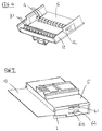
- Fig 2 shows a connection contact (general marking 6) for a flexible printed circuit equipped with an insulation-piercing termination (20) for connection to a supplementary contact, an elongated central portion (21) which forms the floor and an insulation-piercing connection part (22).
- the connection termination may, in particular, be, as shown, of the female type and consist of a cage equipped with one or more elastic contact blades (50).
- the connection termination according to the invention is extended on one of its faces by an elongated central part (21) which is itself extended by a flat zone (22) which forms part of the insulation-piercing connection.
- the elongated central part is equipped with an elastic leg (26), this leg comprising a lug (27) curved under the elongated central part, This leg is destined to work in conjunction with the rim (32) of the lower wall (35) of a housing (1) for receiving the contact (6), as will be explained below.
- the insulation-piercing connection part (22) is elevated with reference to the elongated central part (21) which forms the floor.
- this arrangement makes it possible to remove the insulation-piercing part from the lower wall (35) of the housing which receives the contact.
- the elongated central part of the contact may possess lateral flanks (24, 25). These flanks which extend the lower face of the contact termination serve as a reinforcement of the contact and as a lateral guidance of the contact into its reception cavity (2) in the housing (1). These flanks may comprise a pinch zone (28) around the zone of the elastic leg (26) comprising the lug (27) in such a way as to reinforce, by constriction of the metal, this part which was weakened by the cutting needed to form the leg (26). This pinch zone moreover makes it possible to create a continuous change of level so that the insulation-piercing connection part (22) may become elevated with reference to the elongated central part.
- the termination (20) for connection to a supplementary contact may comprise a cage formed by successive bending in a direction parallel to the contact and comprise a folded shutter (30) at the transition to the elongated central part.
- a single track 100 is shown in Fig 1, it being understood that there are several tracks on the flexible printed circuit.
- Fig 1 shows a general view of a connector for a flexible printed circuit according to the invention which comprises a contact (6) as previously described, a housing (1) equipped with at least one cavity (2) for receiving the said contact (6) for which the contact lug (27) leans, in the pre-insertion position, against the rim (32) of the lower wall (35) of the housing.
- This pre-insertion position makes it possible to supply connectors equipped with their contacts and, in a suitable tool, to position the flexible printed circuit and to crimp in a single operation, all the piercing and crimping components (23,23') on the tracks 100.
- a thrust on the flexible printed circuit in the direction of insertion of the contacts causes the lugs (27) to bend and flatten and makes it possible for the contacts to penetrate fully into the insulator (1).
- the kinematics of insertion of contacts is shown diagramatically in Figs 5A, 5B and 5C, where it is possible to see in section the respective pre-insertion phases of the contact, the contact crimped on the flexible printed circuit and the locked connector.
- the housing (1) and the contact (6) may comprise supplementary means of fastening and retention of the contact in the direction of insertion of the contact.
- These means may consist of a forked leg (51) on the contact, of a first retention stop (52) of the forked leg to prevent the coming out of the contact when it is in the pre-insertion position and a second retention stop (53) of the forked leg in order to retain the contact in a position of complete insertion.
- the lowered cover may perform, aside from a possible contact locking function by the leaning of a ratchet (4) against a shutter (30) arranged at the rear of the contact connection part, the function of holding the flexible printed circuit and the contacts in position by means of the tabs (31) supporting the crimping zone (22).
- the shrouding cover (5) which can bee seen in Fig 4 is movable in a direction perpendicular to the cavitys between a pre-insertion position of the contacts and a position of complete insertion and locking of the contacts. It comprises, for example, a window (60) which receives a lug (61) of the housing (1).
- the shrouding cover When the contacts are completely inserted, the shrouding cover may be pushed vertically into a locked position.
- the locking of the shrouding cover is performed by the latching of the window (60) on a second lug (62).
- the tabs (31) lean on the connection part (22) of the contact with the flexible printed circuit In the locked position the tabs (31) lean on the connection part (22) of the contact with the flexible printed circuit. This leaning places under constraint and bends the crimping part which in its natural position is elevated with respect to the lower wall of the housing.
- the lower wall (35) of the housing (1) comprises ribs (40) which separate the cavitys (2).
- the flexing of the crimping part (22) brings the flexible printed circuit into contact with the ribs framing the contacts and advantageously causes the flexible printed circuit to corrugate under the effect of opposing offset supports.
- the contact may comprise a stop (30), consisting, for example, of a folded shutter of the termination (20) or of the cage of the termination itself, the shrouding cover comprising a supplementary retention ratchet (4) of the contact acting in conjunction with the stop (30) in order to bring about the locking of the contact (6) into the cavity, the shrouding cover being in a closed position.
- a stop (30) consisting, for example, of a folded shutter of the termination (20) or of the cage of the termination itself
- the shrouding cover comprising a supplementary retention ratchet (4) of the contact acting in conjunction with the stop (30) in order to bring about the locking of the contact (6) into the cavity, the shrouding cover being in a closed position.
- the invention does not restrict itself to the example described in the Figures and is, in particular, able to be adapted to any type of termination for connection to a supplementary contact such as, for example, a male termination.
Landscapes
- Coupling Device And Connection With Printed Circuit (AREA)
- Multi-Conductor Connections (AREA)
Applications Claiming Priority (2)
| Application Number | Priority Date | Filing Date | Title |
|---|---|---|---|
| FR9911324 | 1999-09-07 | ||
| FR9911324A FR2798228B1 (fr) | 1999-09-07 | 1999-09-07 | Contact electrique et connecteur pour circuit souple |
Publications (2)
| Publication Number | Publication Date |
|---|---|
| EP1083628A1 true EP1083628A1 (fr) | 2001-03-14 |
| EP1083628B1 EP1083628B1 (fr) | 2006-10-18 |
Family
ID=9549703
Family Applications (1)
| Application Number | Title | Priority Date | Filing Date |
|---|---|---|---|
| EP00118292A Expired - Lifetime EP1083628B1 (fr) | 1999-09-07 | 2000-09-05 | Contact électrique et connecteur pour circuit souple |
Country Status (5)
| Country | Link |
|---|---|
| EP (1) | EP1083628B1 (fr) |
| AT (1) | ATE343231T1 (fr) |
| DE (1) | DE60031342D1 (fr) |
| ES (1) | ES2272226T3 (fr) |
| FR (1) | FR2798228B1 (fr) |
Cited By (2)
| Publication number | Priority date | Publication date | Assignee | Title |
|---|---|---|---|---|
| DE202004001083U1 (de) * | 2004-01-23 | 2005-06-09 | Lear Corporation Electrical And Electronics Gmbh & Co. Kg | Elektrisches Steckverbindergehäuse |
| DE10348005A1 (de) * | 2003-10-15 | 2005-07-07 | Fci | Elektrisches Kontaktelement für Flex-Flachbandkabel |
Citations (5)
| Publication number | Priority date | Publication date | Assignee | Title |
|---|---|---|---|---|
| FR2290768A1 (fr) * | 1974-11-07 | 1976-06-04 | Du Pont Nederland | Dispositif de contact po |
| US4082402A (en) * | 1974-01-09 | 1978-04-04 | Amp Incorporated | Flat flexible cable terminal and electrical connection |
| US4749368A (en) * | 1986-04-03 | 1988-06-07 | E. I. Du Pont De Nemours And Company | Contact strip terminal |
| EP0700124A2 (fr) * | 1994-09-01 | 1996-03-06 | The Whitaker Corporation | Contact électrique ayant une pièce de verrouillage améliorée |
| WO1998033246A1 (fr) * | 1997-01-29 | 1998-07-30 | Ut Automotive Dearborn, Inc. | Procede de connexion d'un cable plat flexible et d'un connecteur |
-
1999
- 1999-09-07 FR FR9911324A patent/FR2798228B1/fr not_active Expired - Fee Related
-
2000
- 2000-09-05 EP EP00118292A patent/EP1083628B1/fr not_active Expired - Lifetime
- 2000-09-05 AT AT00118292T patent/ATE343231T1/de not_active IP Right Cessation
- 2000-09-05 DE DE60031342T patent/DE60031342D1/de not_active Expired - Lifetime
- 2000-09-05 ES ES00118292T patent/ES2272226T3/es not_active Expired - Lifetime
Patent Citations (5)
| Publication number | Priority date | Publication date | Assignee | Title |
|---|---|---|---|---|
| US4082402A (en) * | 1974-01-09 | 1978-04-04 | Amp Incorporated | Flat flexible cable terminal and electrical connection |
| FR2290768A1 (fr) * | 1974-11-07 | 1976-06-04 | Du Pont Nederland | Dispositif de contact po |
| US4749368A (en) * | 1986-04-03 | 1988-06-07 | E. I. Du Pont De Nemours And Company | Contact strip terminal |
| EP0700124A2 (fr) * | 1994-09-01 | 1996-03-06 | The Whitaker Corporation | Contact électrique ayant une pièce de verrouillage améliorée |
| WO1998033246A1 (fr) * | 1997-01-29 | 1998-07-30 | Ut Automotive Dearborn, Inc. | Procede de connexion d'un cable plat flexible et d'un connecteur |
Cited By (3)
| Publication number | Priority date | Publication date | Assignee | Title |
|---|---|---|---|---|
| DE10348005A1 (de) * | 2003-10-15 | 2005-07-07 | Fci | Elektrisches Kontaktelement für Flex-Flachbandkabel |
| DE202004001083U1 (de) * | 2004-01-23 | 2005-06-09 | Lear Corporation Electrical And Electronics Gmbh & Co. Kg | Elektrisches Steckverbindergehäuse |
| DE102004062846B4 (de) * | 2004-01-23 | 2016-02-25 | Lear Corp. | Elektrisches Steckverbindergehäuse |
Also Published As
| Publication number | Publication date |
|---|---|
| ATE343231T1 (de) | 2006-11-15 |
| DE60031342D1 (de) | 2006-11-30 |
| FR2798228A1 (fr) | 2001-03-09 |
| ES2272226T3 (es) | 2007-05-01 |
| FR2798228B1 (fr) | 2001-10-12 |
| EP1083628B1 (fr) | 2006-10-18 |
Similar Documents
| Publication | Publication Date | Title |
|---|---|---|
| US5562478A (en) | Joint connector and a method of assembling a joint connector | |
| EP0001159B2 (fr) | Connecteur électrique | |
| US7137838B2 (en) | Electric connector having contact for connection to a flat, flexible cable | |
| EP2157669A1 (fr) | Connecteur et son procédé d'assemblage | |
| EP0668639B1 (fr) | Douille d'ampoule | |
| JPH0917468A (ja) | 改良された導線保持手段を有する電気コネクタ | |
| US7201604B1 (en) | Ethernet cable connector and methods of use thereof | |
| EP0321285A1 (fr) | Borne bidirectionnelle, pour contacts électriques, à déplacement de l'isolation | |
| US4842529A (en) | Connector with two-piece ground strap | |
| JP2006505105A (ja) | 可撓性リボンケーブル用クランプコネクタ | |
| US20020002002A1 (en) | Press-connecting connector | |
| US20040180582A1 (en) | Connector terminal, a connector and a mounting method | |
| CA1192971A (fr) | Connecteur electrique | |
| US4859204A (en) | Method of staking a wave crimp for flat power cable termination | |
| CA1150378A (fr) | Plaque de branchement ajouree transformable en plaque a broches | |
| US5611716A (en) | Electrical contact having improved secondary locking surfaces | |
| EP0570039B1 (fr) | Borne électrique | |
| EP1083628B1 (fr) | Contact électrique et connecteur pour circuit souple | |
| JPS6276176A (ja) | 電気コネクタ組立体 | |
| EP0342868B1 (fr) | Terminal électrique pour câble de puissance plat | |
| EP1979989A1 (fr) | Contact avec element de retention ameliore | |
| JPS6038840B2 (ja) | 雌型電気接続子の製造方法 | |
| JP2020087671A (ja) | 端子接続構造 | |
| US20060246767A1 (en) | Wire-terminal element | |
| JP2986005B2 (ja) | 逆挿入防止用コネクタ |
Legal Events
| Date | Code | Title | Description |
|---|---|---|---|
| PUAI | Public reference made under article 153(3) epc to a published international application that has entered the european phase |
Free format text: ORIGINAL CODE: 0009012 |
|
| AK | Designated contracting states |
Kind code of ref document: A1 Designated state(s): AT BE CH CY DE DK ES FI FR GB GR IE IT LI LU MC NL PT SE |
|
| AX | Request for extension of the european patent |
Free format text: AL;LT;LV;MK;RO;SI |
|
| 17P | Request for examination filed |
Effective date: 20010903 |
|
| AKX | Designation fees paid |
Free format text: AT BE CH CY DE DK ES FI FR GB GR IE IT LI LU MC NL PT SE |
|
| GRAP | Despatch of communication of intention to grant a patent |
Free format text: ORIGINAL CODE: EPIDOSNIGR1 |
|
| GRAS | Grant fee paid |
Free format text: ORIGINAL CODE: EPIDOSNIGR3 |
|
| RAP1 | Party data changed (applicant data changed or rights of an application transferred) |
Owner name: FCI |
|
| GRAA | (expected) grant |
Free format text: ORIGINAL CODE: 0009210 |
|
| AK | Designated contracting states |
Kind code of ref document: B1 Designated state(s): AT BE CH CY DE DK ES FI FR GB GR IE IT LI LU MC NL PT SE |
|
| PG25 | Lapsed in a contracting state [announced via postgrant information from national office to epo] |
Ref country code: IT Free format text: LAPSE BECAUSE OF FAILURE TO SUBMIT A TRANSLATION OF THE DESCRIPTION OR TO PAY THE FEE WITHIN THE PRE;WARNING: LAPSES OF ITALIAN PATENTS WITH EFFECTIVE DATE BEFORE 2007 MAY HAVE OCCURRED AT ANY TIME BEFORE 2007. THE CORRECT EFFECTIVE DATE MAY BE DIFFERENT FROM THE ONE RECORDED.SCRIBED TIME-LIMIT Effective date: 20061018 Ref country code: BE Free format text: LAPSE BECAUSE OF FAILURE TO SUBMIT A TRANSLATION OF THE DESCRIPTION OR TO PAY THE FEE WITHIN THE PRESCRIBED TIME-LIMIT Effective date: 20061018 Ref country code: NL Free format text: LAPSE BECAUSE OF FAILURE TO SUBMIT A TRANSLATION OF THE DESCRIPTION OR TO PAY THE FEE WITHIN THE PRESCRIBED TIME-LIMIT Effective date: 20061018 Ref country code: FI Free format text: LAPSE BECAUSE OF FAILURE TO SUBMIT A TRANSLATION OF THE DESCRIPTION OR TO PAY THE FEE WITHIN THE PRESCRIBED TIME-LIMIT Effective date: 20061018 Ref country code: CH Free format text: LAPSE BECAUSE OF FAILURE TO SUBMIT A TRANSLATION OF THE DESCRIPTION OR TO PAY THE FEE WITHIN THE PRESCRIBED TIME-LIMIT Effective date: 20061018 Ref country code: AT Free format text: LAPSE BECAUSE OF FAILURE TO SUBMIT A TRANSLATION OF THE DESCRIPTION OR TO PAY THE FEE WITHIN THE PRESCRIBED TIME-LIMIT Effective date: 20061018 Ref country code: LI Free format text: LAPSE BECAUSE OF FAILURE TO SUBMIT A TRANSLATION OF THE DESCRIPTION OR TO PAY THE FEE WITHIN THE PRESCRIBED TIME-LIMIT Effective date: 20061018 |
|
| REG | Reference to a national code |
Ref country code: GB Ref legal event code: FG4D |
|
| REG | Reference to a national code |
Ref country code: CH Ref legal event code: EP Ref country code: IE Ref legal event code: FG4D |
|
| REF | Corresponds to: |
Ref document number: 60031342 Country of ref document: DE Date of ref document: 20061130 Kind code of ref document: P |
|
| PG25 | Lapsed in a contracting state [announced via postgrant information from national office to epo] |
Ref country code: DK Free format text: LAPSE BECAUSE OF FAILURE TO SUBMIT A TRANSLATION OF THE DESCRIPTION OR TO PAY THE FEE WITHIN THE PRESCRIBED TIME-LIMIT Effective date: 20070118 Ref country code: SE Free format text: LAPSE BECAUSE OF FAILURE TO SUBMIT A TRANSLATION OF THE DESCRIPTION OR TO PAY THE FEE WITHIN THE PRESCRIBED TIME-LIMIT Effective date: 20070118 |
|
| PG25 | Lapsed in a contracting state [announced via postgrant information from national office to epo] |
Ref country code: DE Free format text: LAPSE BECAUSE OF FAILURE TO SUBMIT A TRANSLATION OF THE DESCRIPTION OR TO PAY THE FEE WITHIN THE PRESCRIBED TIME-LIMIT Effective date: 20070119 |
|
| PG25 | Lapsed in a contracting state [announced via postgrant information from national office to epo] |
Ref country code: PT Free format text: LAPSE BECAUSE OF FAILURE TO SUBMIT A TRANSLATION OF THE DESCRIPTION OR TO PAY THE FEE WITHIN THE PRESCRIBED TIME-LIMIT Effective date: 20070319 |
|
| ET | Fr: translation filed | ||
| NLV1 | Nl: lapsed or annulled due to failure to fulfill the requirements of art. 29p and 29m of the patents act | ||
| REG | Reference to a national code |
Ref country code: CH Ref legal event code: PL |
|
| REG | Reference to a national code |
Ref country code: ES Ref legal event code: FG2A Ref document number: 2272226 Country of ref document: ES Kind code of ref document: T3 |
|
| PLBE | No opposition filed within time limit |
Free format text: ORIGINAL CODE: 0009261 |
|
| STAA | Information on the status of an ep patent application or granted ep patent |
Free format text: STATUS: NO OPPOSITION FILED WITHIN TIME LIMIT |
|
| 26N | No opposition filed |
Effective date: 20070719 |
|
| PG25 | Lapsed in a contracting state [announced via postgrant information from national office to epo] |
Ref country code: GR Free format text: LAPSE BECAUSE OF FAILURE TO SUBMIT A TRANSLATION OF THE DESCRIPTION OR TO PAY THE FEE WITHIN THE PRESCRIBED TIME-LIMIT Effective date: 20070119 Ref country code: MC Free format text: LAPSE BECAUSE OF NON-PAYMENT OF DUE FEES Effective date: 20070930 |
|
| GBPC | Gb: european patent ceased through non-payment of renewal fee |
Effective date: 20070905 |
|
| PG25 | Lapsed in a contracting state [announced via postgrant information from national office to epo] |
Ref country code: IE Free format text: LAPSE BECAUSE OF NON-PAYMENT OF DUE FEES Effective date: 20070905 |
|
| PG25 | Lapsed in a contracting state [announced via postgrant information from national office to epo] |
Ref country code: GB Free format text: LAPSE BECAUSE OF NON-PAYMENT OF DUE FEES Effective date: 20070905 |
|
| PG25 | Lapsed in a contracting state [announced via postgrant information from national office to epo] |
Ref country code: CY Free format text: LAPSE BECAUSE OF FAILURE TO SUBMIT A TRANSLATION OF THE DESCRIPTION OR TO PAY THE FEE WITHIN THE PRESCRIBED TIME-LIMIT Effective date: 20061018 Ref country code: LU Free format text: LAPSE BECAUSE OF NON-PAYMENT OF DUE FEES Effective date: 20070905 |
|
| REG | Reference to a national code |
Ref country code: FR Ref legal event code: CA |
|
| REG | Reference to a national code |
Ref country code: FR Ref legal event code: TP |
|
| PGFP | Annual fee paid to national office [announced via postgrant information from national office to epo] |
Ref country code: ES Payment date: 20110905 Year of fee payment: 12 Ref country code: FR Payment date: 20110901 Year of fee payment: 12 |
|
| REG | Reference to a national code |
Ref country code: FR Ref legal event code: ST Effective date: 20130531 |
|
| PG25 | Lapsed in a contracting state [announced via postgrant information from national office to epo] |
Ref country code: FR Free format text: LAPSE BECAUSE OF NON-PAYMENT OF DUE FEES Effective date: 20121001 |
|
| REG | Reference to a national code |
Ref country code: ES Ref legal event code: FD2A Effective date: 20131018 |
|
| PG25 | Lapsed in a contracting state [announced via postgrant information from national office to epo] |
Ref country code: ES Free format text: LAPSE BECAUSE OF NON-PAYMENT OF DUE FEES Effective date: 20120906 |