EP1083697A2 - Verfahren und Vorrichtung zum Einfügen und Abzweigen von optischen Kanälen - Google Patents
Verfahren und Vorrichtung zum Einfügen und Abzweigen von optischen Kanälen Download PDFInfo
- Publication number
- EP1083697A2 EP1083697A2 EP00306023A EP00306023A EP1083697A2 EP 1083697 A2 EP1083697 A2 EP 1083697A2 EP 00306023 A EP00306023 A EP 00306023A EP 00306023 A EP00306023 A EP 00306023A EP 1083697 A2 EP1083697 A2 EP 1083697A2
- Authority
- EP
- European Patent Office
- Prior art keywords
- wavelength
- channel
- wdm signal
- filter
- filtering
- Prior art date
- Legal status (The legal status is an assumption and is not a legal conclusion. Google has not performed a legal analysis and makes no representation as to the accuracy of the status listed.)
- Withdrawn
Links
- 230000003287 optical effect Effects 0.000 title claims abstract description 8
- 238000000034 method Methods 0.000 title claims description 15
- 238000001914 filtration Methods 0.000 claims abstract description 50
- 239000000835 fiber Substances 0.000 claims description 21
- 238000012876 topography Methods 0.000 abstract description 2
- 238000000605 extraction Methods 0.000 description 19
- 238000003780 insertion Methods 0.000 description 15
- 230000037431 insertion Effects 0.000 description 15
- 238000013461 design Methods 0.000 description 7
- 238000002955 isolation Methods 0.000 description 7
- 230000005540 biological transmission Effects 0.000 description 6
- 239000000284 extract Substances 0.000 description 4
- 238000010586 diagram Methods 0.000 description 3
- 239000013307 optical fiber Substances 0.000 description 3
- 238000012545 processing Methods 0.000 description 3
- 238000004891 communication Methods 0.000 description 2
- 230000007423 decrease Effects 0.000 description 2
- 230000003247 decreasing effect Effects 0.000 description 1
- 230000008030 elimination Effects 0.000 description 1
- 238000003379 elimination reaction Methods 0.000 description 1
- 238000012986 modification Methods 0.000 description 1
- 230000004048 modification Effects 0.000 description 1
- 238000012552 review Methods 0.000 description 1
Images


Classifications
-
- H—ELECTRICITY
- H04—ELECTRIC COMMUNICATION TECHNIQUE
- H04J—MULTIPLEX COMMUNICATION
- H04J14/00—Optical multiplex systems
- H04J14/02—Wavelength-division multiplex systems
- H04J14/0201—Add-and-drop multiplexing
- H04J14/0202—Arrangements therefor
- H04J14/0213—Groups of channels or wave bands arrangements
-
- H—ELECTRICITY
- H04—ELECTRIC COMMUNICATION TECHNIQUE
- H04J—MULTIPLEX COMMUNICATION
- H04J14/00—Optical multiplex systems
- H04J14/02—Wavelength-division multiplex systems
- H04J14/0201—Add-and-drop multiplexing
- H04J14/0202—Arrangements therefor
- H04J14/0206—Express channels arrangements
-
- H—ELECTRICITY
- H04—ELECTRIC COMMUNICATION TECHNIQUE
- H04J—MULTIPLEX COMMUNICATION
- H04J14/00—Optical multiplex systems
- H04J14/02—Wavelength-division multiplex systems
- H04J14/0201—Add-and-drop multiplexing
- H04J14/0202—Arrangements therefor
- H04J14/0209—Multi-stage arrangements, e.g. by cascading multiplexers or demultiplexers
Definitions
- This invention relates generally to filter designs and more specifically to both apparatus and network level filter topographies for Optical Add-Drop Multiplexers (OADMs).
- OADMs Optical Add-Drop Multiplexers
- Wavelength Division Multiplexed (WDM) systems employ WDM signals consisting of a number of optical signals at different wavelengths, hereinafter referred to as channels or information carrier signals, to transmit information on optical fiber cables. Each channel is modulated by one or more information signal, resulting in the capability to transmit a significant number of information signals over a single optical fiber cable. It is recognized that although a WDM signal comprises a plurality of wavelengths capable of carrying channels, not all the wavelength must contain a channel.
- OADMs are employed that consist of a plurality of optical filters. These OADMs are used to selectively extract Channels, hereinafter referred to as drop channels, from a WDM signal while the remaining channels, hereinafter referred to as through channels, travel through.
- the OADMs can also be used to add channels, hereinafter referred to as add channels, to a WDM signal, using wavelengths that have been vacated as a result of channels being dropped at the OADM in question or at an OADM earlier in the transmission path. Since more than one channel usually needs to be accessed at a network node, multi-channel OADMs are used such that a plurality of channels can be dropped and/or added from and/or to a received WDM signal.
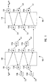
- FIGURE 1 depicts an OADM that comprises a separate channel demultiplexer 102 and channel multiplexer 104.
- the demultiplexer 102 extracts channels from a WDM signal while the multiplexer 104 inserts channels within the WDM signal output from the demultiplexer 102.
- the channel demultiplexer 102 in this case with four channels to be dropped, comprises a first alignment block 106, first and second columnating lenses (CL) 108,110, first, second, third and fourth drop filters (DF) 112a,112b,112c,112d and first, second, third and fourth clean-up filters (CF) 114a,114b,114c,114d.
- the alignment block 106 is utilized to ensure that beams of light being transmitted between the filters and columnating lenses are aligned properly for optimal performance.
- the first columnating lens 108 receives an input WDM signal S IN (t) in a form capable of being transmitted on a fiber optic cable, transforms the signal into an extended beam signal, and transmits the extended beam WDM signal in the direction of the first drop filter 112a.
- the drop filter 112a receives the extended beam WDM signal, filters out a channel at wavelength ⁇ 1 with the use of a single wavelength filter, and forwards the remainder of the extended beam WDM signal onto the next drop filter 112b.
- the isolation of the channel at wavelength ⁇ 1 is not perfect and so an additional filter maybe required to ensure that only the required channel is sent on for further processing, in this case this is done with the first clean-up filter 114a.
- Additional pairings of drop and clean-up filters proceed within the channel demultiplexer 102 of the OADM, each operating similar to that of the first drop and clean-up filters 112a,114a but for different wavelengths ( ⁇ 2, ⁇ 3, ⁇ 4).
- the resulting extended beam WDM signal is received by the second columnating lens 110 which converts the signal to a form transmittable over fiber optic cable.
- the signal output from the second columnating lens 110 although not carrying the channels that were dropped within the demultiplexer 102 of the OADM, still may contain channels at other wavelengths.
- the channel multiplexer 104 of the OADM of FIGURE 1 comprises a second alignment block 116, third and fourth columnating lenses 118,120 and first, second, third and fourth add filters 122a,122b,122c,122d.
- the second alignment block 116 operates in a similar manner to the first alignment block 106, as do the third and fourth columnating lenses 118,120 with respect to the first and second columnating lenses 108,110 respectively.
- Each of the add filters 122a,122b,122c,122d are single wavelength filters that insert channels at the wavelengths ⁇ 1, ⁇ 2, ⁇ 3, and ⁇ 4 respectively.
- An output WDM signal S OUT (t) that is similar to the input WDM signal S IN (t) but with different channels at wavelengths ⁇ 1 through ⁇ 4 is transmitted from the fourth columnating lens 120.
- an OADM is a band OADM as depicted within FIGURE 2.
- an input WDM signal S IN (t) is received at a first band filter 202 which extracts a band of wavelengths, in this case wavelengths ⁇ 1 through ⁇ 4, and passes a WDM signal comprising the remaining channels to an isolation filter 204.
- the isolation filter 204 ensures that no channels are at wavelengths ⁇ 1 through ⁇ 4 without extracting or inserting any channels at other wavelengths.
- the isolation filter 204 outputs the resulting WDM signal to a second band filter 206 at which point a band of wavelengths, in this case ⁇ 1 through ⁇ 4, are inserted, generating an output WDM signal S OUT (t).
- the channels that are extracted at the first band filter 202 are separated by a series of single wavelength drop filters 208a,208b,208c,208d. These individual channels are then further filtered with respective clean-up filters 212a,212b,212c,212d and output for further processing. As depicted in FIGURE 2, the channels inserted at the second band filter 206 are combined prior to the insertion with the use of a series of single wavelength add filters 212a,212b,212c,212d.
- the band OADM of FIGURE 2 has a large number of required filters. As can be seen for the case within FIGURE 2, twelve single wavelength filters are required for the drop, clean-up, and add filters along with three four wavelength filters for the first and second band filters 202,206 and the isolation filter 204. In general, it can be seen for the case of a band of N wavelengths being dropped and added, there would be 3N single wavelength filters and three N wavelength filters required.
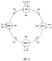
- FIGURE 3 This network comprises a hub 302 and first, second, and third network nodes 304,306,308. As depicted in FIGURE 3, the hub 302 communicates independently with each of the nodes 304,306,308 through the fiber optic cables 310,312,314,316. These cables are connected up within a ring configuration that has all transmissions in one direction. In this case, the hub 302 comprises a multi-channel OADM capable of dropping and adding the channels at wavelengths ⁇ 1, ⁇ 2, and ⁇ 3.
- the nodes 304,306,308 each comprise a single wavelength OADM for dropping and adding channels at respective wavelengths ⁇ 1, ⁇ 2, and ⁇ 3.
- the hub 302 communicates with the first node 304 via the channel at wavelength ⁇ 1, the second node 306 via the channel at wavelength ⁇ 2, and the third node 308 via the channel at wavelength ⁇ 3.
- the key difficulty with the network configuration as depicted within FIGURE 3 is the cost of the OADM within each of the network nodes. Since the same wavelength that is being dropped is also being added at the same node, the tolerance of the single wavelength filters within the OADMs must be extremely high to prevent cross-talk problems. Alternatively, isolation filters are required.
- a typical solution is to use a first set of channels for transmission from the hub 302 to the nodes 304,306,308 and another set of channels for transmission from the nodes to the hub. For instance, this could be done by using wavelengths ⁇ 1, ⁇ 2, and ⁇ 3 for transmitting data to the respective network nodes 304,306,308, similar to that shown in FIGURE 3, and using wavelengths ⁇ 4, ⁇ 5, and ⁇ 6 for transmitting data to the hub 302 from the respective nodes 304,306,308.
- the key problem with this is that the bandwidth efficiency of the network becomes only 50% as at any one time only half the channels are being used.
- a further solution to improve the cost of OADMs is not to insert channels within adjacent wavelengths.
- Such unused wavelengths commonly called dead bands, allow a relaxation of the tolerances required for the filters used by decreasing the ratio of passband to dead band.
- the bandwidth efficiency of the overall network is significantly reduced. For every used wavelength there is an unused wavelength, making the efficiency 50%. In situations where the bandwidth of the network is critical such a low bandwidth efficiency is not acceptable.
- OADM designs and network configurations of OADMs are required that reduce the overall cost of the network while not limiting the bandwidth efficiency. To accomplish this, the number of filters and the tolerance of the filters must be reduced without significantly sacrificing the limited bandwidth of the network.
- the present invention has specific filter topologies at the apparatus and/or network level of a WDM network to mitigate one or more of the disadvantages with regard to the present invention.
- the present invention takes advantage of wavelengths within a WDM signal that do not have channels.
- the key to the present invention is to organize the filters within an apparatus or a network so that a filtering apparatus receives a WDM signal with an empty wavelength. In a first possibility, this allows multiple tasks to be possible during a single filtering operation, such as inserting a channel and removing another channel with a single filter. In a second possibility, the tolerance of filters within the filtering apparatus can be reduced. In either case, the result should be a lower cost due to either a reduced number of filters or reduced tolerances on those filters used.
- the present invention in a first broad aspect, is a method of inserting a channel into a WDM signal.
- the first step of the method is to receive a first WDM signal that has no channel at a first wavelength.
- the first WDM signal is filtered so that a channel at a second wavelength adjacent to the first wavelength is removed from the WDM signal and a channel is inserted at the first wavelength. This results in the generation of a second WDM signal.
- the filtering of the first WDM signal is done with use of a single filter which has a passband comprising both the first and second wavelengths.
- the filtering is done with two filters with passbands comprising the first and second wavelengths respectively that have asymmetrically reduced tolerances.
- the present invention is a filtering apparatus that is arranged to implement the method of the first broad aspect.
- the filtering apparatus filters the first WDM signal so that a channel at a second wavelength adjacent to the first wavelength is removed from the WDM signal and a channel is inserted at the first wavelength.
- the filtering apparatus outputs a second WDM signal generated from the filtering of the first WDM signal that has no channel at the second wavelength.
- this filtering is done with a single filter while in another embodiment it is done with two filters with lower tolerances.
- the present invention is an OADM or a network node that incorporates one or more of the filtering apparatuses of the second broad aspect.
- the present invention is an OADM which includes an initial filter, a number of intermediate filters that are consistent with the filtering apparatus of the second broad aspect, and a final filter, the OADM performing both demultiplexing and multiplexing operations on a WDM signal.
- the present invention is a network that includes a hub and a number of network nodes that further include a filtering apparatus according to the second broad aspect.
- the key to one preferred embodiment of the present invention is to configure filters within an OADM so that the number of filters can be reduced compared to previous implementations with similar functionality.
- the key to another of the preferred embodiments of the present invention is to configure the OADMs within a network so as to reduce the required tolerances for the filters within the OADMs of the network nodes.
- the configurations described herein below for the preferred embodiments of the present invention utilize the lack of a channel at a particular wavelength, hereinafter referred to as an empty wavelength, as an advantage during a filtering stage for a WDM signal.
- the lack of a channel at a particular wavelength within the received WDM signal allows the filtering stage to remove a channel from a wavelength adjacent to the empty wavelength while inserting a new channel at the previously empty wavelength with the use of only a single filter.
- the existence of an empty wavelength within the received WDM signal allows the next filtering stage to perform the functions of the first preferred embodiment but with two filters of a lower tolerance than previous implementations and hence a lower cost.
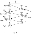
- This OADM comprises an alignment block 402, first and second columnating lenses (CL) 404,406, first and second single wavelength filters (1 ⁇ F) 408a,408b, first, second, and third two wavelength filters (2 ⁇ F) 410a,410b,410c, and first, second, third, and fourth clean-up filters (CF) 412a,412b,412c,412d.
- CL first and second columnating lenses
- CF clean-up filters
- the first columnating lens 404 receives an input WDM signal S IN (t) which comprises a plurality of channels at different wavelengths.
- the columnating lens 404 converts the WDM signal S IN (t) from a form transmitted on a fiber optic cable to an extended beam WDM signal and transmits the extended beam WDM signal to the first single wavelength filter 408a via the alignment block 402.
- the single wavelength filter 408a is a three port filter in which a particular channel, in this case at wavelength ⁇ 1, is extracted from the extended beam WDM signal and forwarded to the first clean-up filter 412a.
- the clean-up filter 412a ensures that only the channel at wavelength ⁇ 1 is sent for processing while any other wavelengths extracted unintentionally at the first single wavelength filter 408a are removed.
- the resulting extended beam WDM signal with the channel at wavelength ⁇ 1 removed is reflected at the first single wavelength filter 408a and transmitted via the alignment block 402 to the first two wavelength filter 410a.
- This resulting WDM signal although comprising the same wavelengths as the WDM signal received at the first single wavelength filter 408a, is in fact a different WDM signal since it contains different channels.
- the WDM signals generated between filters in the OADM of FIGURE 4 are herein below referred to as intermediate WDM signals.
- the first two wavelength filter 410a is a four port filter that receives the intermediate signal output from the filter 408a and filters it such that a particular channel, at wavelength ⁇ 2 in FIGURE 4, is extracted while a channel is inserted at the wavelength removed at the previous filter 408a, in this case wavelength ⁇ 1. Similar to the operation of the first clean-up filter 412a, the second clean-up filter 412b is used to further filter the extracted channel at wavelength ⁇ 2. The insertion of the channel at wavelength ⁇ 1 is possible with the same filter as the extraction of the channel at wavelength ⁇ 2 since the wavelengths are adjacent and the channel at wavelength ⁇ 1 has previously been removed and so will not contaminate the extraction of the channel at wavelength ⁇ 2.
- the first two wavelength filter 410a can filter off the channels at these wavelengths from the received intermediate WDM signal, in this case only the channel at wavelength ⁇ 2 remains, and can insert channels at these wavelengths, in this case a channel at wavelength ⁇ 1. If a channel was also inserted for wavelength ⁇ 2, cross-talk problems could result with the inserted channel at wavelength ⁇ 2 also being extracted. The end result of these operations is an outputting of a further intermediate WDM signal.
- the second and third two wavelength filters 410b,410c and third and fourth clean-up filters 412c,412d operate in a similar manner as the first two wavelength filter 410a and the second clean-up filter 412b respectively.
- the second two wavelength filter 410b and third clean-up filter 412c operate together to extract the channel at wavelength ⁇ 3 and insert a channel at wavelength ⁇ 2.
- the third two wavelength filter 410c and fourth clean-up filter 412d operate together to extract the channel at wavelength ⁇ 4 and insert a channel at wavelength ⁇ 3.
- the second single wavelength filter 408b receives the intermediate WDM signal output from the third two wavelength filter 410c and inserts a channel at wavelength ⁇ 4, the wavelength that corresponds to the channel removed at the filter 410c.
- the resulting WDM signal is then reflected to the second columnating lens 406 which converts the signal into a form that can be transmitted along a fiber optic cable as output WDM signal S OUT (t).
- the key to the preferred embodiment OADM of FIGURE 4 is the removal of a channel at a wavelength directly prior to the insertion of a channel at the same wavelength.
- the same filter (a four port two wavelength filter) may be used for the insertion of a channel at the previously extracted wavelength and the extraction of a channel at an adjacent wavelength.
- FIGURE 4 There are a number of problems with this embodiment, but the advantages as will be described herein below in most cases out way these problems.
- One problem with the embodiment of FIGURE 4 is the difficulty of aligning the four port filters required to be used for the two wavelength filters.
- Another problem is the increased cost required with the use of these two wavelength filters due to the increased passband needed, that being a passband wide enough for two wavelengths.
- FIGURE 4 There are a number of important advantages of the OADM as depicted in FIGURE 4 over the previous implementations. For one, the number of filters is significantly reduced. It can be seen in FIGURE 4 that only nine filters were required to operate an OADM for four wavelengths while in the OADM implementations of FIGURES 1 and 2 twelve and fifteen filters were needed respectively. In general, with N wavelengths being extracted and inserted within the embodiment of FIGURE 4, it can be seen that 2N+1 filters would be required. Therefore, as the number of wavelengths requiring extraction and insertion increases, the advantages of the preferred embodiment of FIGURE 4 increase since the OADM implementations of FIGURES 1 and 2 require 3N and 3N+3 filters respectively. A further advantage of the preferred embodiment of FIGURE 4 is that no dead bands are required.
- FIGURE 4 allows for lower through loss when compared to a single channel ADM cascade as depicted within FIGURE 1. In FIGURE 4, only five filter bounces are required for a four channel add/drop functionality while in FIGURE 1, eight filter bounces are needed for similar functionality.
- FIGURE 4 There are numerous alternative embodiments possible for the preferred embodiment depicted in FIGURE 4.
- the preferred embodiment of FIGURE 4 is depicted using an alignment block 402 and an extended beam signal, the present invention could be implemented in a 3 and 4 port design in which fiber optic cable connects the individual filters of the OADM with additional columnating lenses included on either side of each filter.
- the embodiment depicted in FIGURE 4 utilizes clean-up filters, these filters are not required in embodiments in which the filters extracting the channels are of sufficiently high tolerance.
- the OADM of FIGURE 4 operates to extract and insert four wavelengths, this is not meant to limit the scope of the present invention. More or less wavelengths can be extracted and/or inserted while still implementing an OADM of the preferred embodiment of FIGURE 4.
- the key to this embodiment is that a WDM signal is received at a filter with an empty wavelength, and the single filter subsequently can extract a channel at a wavelength adjacent to the empty wavelength at the same time as inserting a channel at the previously empty wavelength.
- the network depicted within FIGURE 5 comprises a communication hub 502 and first, second, and third network nodes 504,506,508.
- the hub 502 and the network nodes 504,506,508 together make a ring configuration with a first fiber optic cable 510 coupled between the hub 502 and the first node 504, a second fiber optic cable 512 coupled between the first and second nodes 504,506, a third fiber optic cable 514 coupled between the second and third nodes 506,508, and a fourth fiber optic cable 516 coupled between the third node 508 and the hub 502.
- a WDM signal with at least four channels is transmitted through the ring created with the hub 502 and the nodes 504,506,508.
- the hub 502 transmits data to the first, second and third nodes 504,506,508 within channels at respective wavelengths ⁇ 2, ⁇ 3 and ⁇ 4, and receives data from the first, second and third nodes 504,506,508 within channels at respective wavelengths ⁇ 1, ⁇ 2 and ⁇ 3.
- the first, second, third and fourth fiber optic cables 510,512,514,516 have WDM signals that comprise channels at wavelengths ⁇ 2,3,4, ⁇ 1,3,4, ⁇ 1,2,4 and ⁇ 1,2,3 respectively transmitted through them.
- a channel at wavelength ⁇ 2 is inserted within a WDM signal by the hub 502 and extracted by the first network node 504.
- a channel at wavelength ⁇ 1 is inserted to the received WDM signal at the first node 504 and extracted at the hub 502. Similar operations allow the remaining nodes 506,508 to communicate with the hub 502.
- the key to this preferred embodiment of the present invention is the extraction of a channel on a first wavelength by a first network device and then not inserting a new channel on the first wavelength until at a further network device. This results in a distance in which no channel is on a particular wavelength, hence an empty wavelength.
- These empty wavelengths being transmitted between network devices within the ring configuration allow other wavelengths to be extracted with filters of reduced cost as will be described in detail with reference to FIGURE 6.
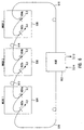
- FIGURE 6 A block diagram of a preferred embodiment of the network configuration of FIGURE 5 is depicted in FIGURE 6.
- the first, second and third network nodes 504,506,508 each comprise an extraction filter 602a,602b,602c and an insertion filter 604a,604b,604c.
- the extraction filter 602a removes the channel at wavelength ⁇ 2 from the WDM signal received at the first node 504 and the insertion filter 604a adds a channel at wavelength ⁇ 1 to the WDM signal output from the extraction filter 602a.
- channels at wavelengths ⁇ 3 and ⁇ 4 are removed by the extraction filters 602b,602c respectively and channels at wavelengths ⁇ 2 and ⁇ 3 are added by the insertion filters 604b,604c respectively.
- FIGURES 5 and 6 allows for the extraction filters 602a,602b,602c and the insertion filters 604a,604b,604c to have asymmetrically lower tolerances than would be required in the well-known embodiment depicted in FIGURE 3.
- the extraction filter 602a for the channel at wavelength ⁇ 2 can be made with lower tolerances on the ⁇ 1 side of the filter.
- a filter that has a passband comprising wavelength ⁇ 2 and has a tolerance that could pass a portion of a channel at wavelength ⁇ 1 may be used without significant corruption of the extracted channel since at this point no channel is at wavelength ⁇ 1.
- the other extraction filters 602b,602c can also have asymmetrically lower tolerances than previous designs would require.
- the extraction filter 602b can be designed to have a passband comprising wavelength ⁇ 3 while also having a tolerance that allows any channel at wavelength ⁇ 2 to be removed as well since, in this case, no channels are at wavelength ⁇ 2 at this point.
- the extraction filter 602c can be designed to have a passband comprising wavelength ⁇ 4 without fully preventing a channel at wavelength ⁇ 3 from being removed.
- the insertion filters 604a,604b,604c can also have asymmetrically reduced tolerances.
- the insertion filter 604a for instance can allow a channel at wavelength ⁇ 1 to be inserted by having a passband comprising wavelength ⁇ 1 while not fully preventing the removal of a channel on wavelength ⁇ 2 due to a low tolerance. Since, in the case depicted in FIGURE 6, no channel is at wavelength ⁇ 2 when inserting a channel at wavelength ⁇ 1, there is no need to ensure that filter 604a doesn't affect signals at wavelength ⁇ 2. This low tolerance on one side of the insertion filter 604a could actually be used to ensure the remaining channel at wavelength ⁇ 2 has been removed from the WDM signal traversing it. Similar asymmetrical tolerance relaxations can be used with the insertion filters 604b,604c for wavelength ⁇ 3 and ⁇ 4 respectively when inserting a channel at wavelengths ⁇ 2 and ⁇ 3 respectively.
- FIGURES 5 and 6 One key advantage of the embodiment depicted in FIGURES 5 and 6 is the reduced costs for the filters as a result of the decrease in the tolerance requirement of the extraction and insertion filters within the network nodes. This embodiment does not affect tolerance requirements of the filters within the hub 502, though an OADM according to the preferred embodiment of the present invention depicted within FIGURE 4 could be used within the hub 502 to reduce the number of filters required.
- FIGURES 5 and 6 Another advantage of the embodiment of the present invention depicted in FIGURES 5 and 6 is a reduction in the cross-talk within the network, cross-talk being the accidental extraction of a channel at a wavelength other than the wavelength attempting to be extracted from.
- a sufficiently large reduction in cross-talk can result in the elimination of the need for clean-up filters, hence reducing the cost of the OADMs within the nodes 504,506,508.
- the reduction in cross-talk can further reduce the through loss.
- the embodiment of FIGURES 5 and 6 further do not require any dead bands. Because of the lack of dead bands, the bandwidth efficiency of the embodiment depicted in FIGURES 5 and 6 is N-1/N where N is the number of wavelengths (one more than the number of network nodes). Within any one fiber optic cable, all but one wavelength is being used for transmission of channels. In the case shown in FIGURES 5 and 6, N equals four and so the efficiency is 75%. Other OADM schemes have bandwidth efficiencies between 50% to 75% and so the network configuration of FIGURES 5 and 6 can result in an increased efficiency, especially as N increases.
- more than one wavelength is extracted and inserted at one or more of the network nodes.
- either more than one extraction and insertion filters are used or, in the case of adjacent wavelengths requiring extraction, an extraction filter is used for a band of wavelengths.
- more than one wavelength would be empty during the transmission on the fiber optic cables, hence adjusting the calculation with respect to bandwidth efficiency.
Landscapes
- Engineering & Computer Science (AREA)
- Computer Networks & Wireless Communication (AREA)
- Signal Processing (AREA)
- Optical Communication System (AREA)
- Optical Filters (AREA)
- Small-Scale Networks (AREA)
Applications Claiming Priority (2)
| Application Number | Priority Date | Filing Date | Title |
|---|---|---|---|
| US390213 | 1999-09-08 | ||
| US09/390,213 US6188816B1 (en) | 1999-09-08 | 1999-09-08 | Filter topologies for optical add-drop multiplexers |
Publications (2)
| Publication Number | Publication Date |
|---|---|
| EP1083697A2 true EP1083697A2 (de) | 2001-03-14 |
| EP1083697A3 EP1083697A3 (de) | 2003-04-16 |
Family
ID=23541580
Family Applications (1)
| Application Number | Title | Priority Date | Filing Date |
|---|---|---|---|
| EP00306023A Withdrawn EP1083697A3 (de) | 1999-09-08 | 2000-07-14 | Verfahren und Vorrichtung zum Einfügen und Abzweigen von optischen Kanälen |
Country Status (4)
| Country | Link |
|---|---|
| US (1) | US6188816B1 (de) |
| EP (1) | EP1083697A3 (de) |
| JP (1) | JP2001127738A (de) |
| CA (1) | CA2312189A1 (de) |
Cited By (2)
| Publication number | Priority date | Publication date | Assignee | Title |
|---|---|---|---|---|
| WO2005022801A1 (en) * | 2003-08-27 | 2005-03-10 | Alcatel | Branching unit with full or partial broadcast of wavelengths |
| EP1355440A3 (de) * | 2002-04-19 | 2006-07-26 | Fujitsu Limited | Vorrichtung zur Übertragung im Wellenlängenmultiplex |
Families Citing this family (14)
| Publication number | Priority date | Publication date | Assignee | Title |
|---|---|---|---|---|
| US6285508B1 (en) * | 1999-06-30 | 2001-09-04 | Radiant Research Inc. | Beam splitting ball lens method for its manufacture and apparatus for its packaging |
| US20010046350A1 (en) * | 2000-02-25 | 2001-11-29 | Tedesco James M. | Configurable Wavelength routing device |
| US6332050B1 (en) * | 2000-04-05 | 2001-12-18 | Board Of Supervisors Of Louisiana State University And Agricultural And Mechanical College | Optical slab waveguide for massive, high-speed interconnects |
| US7116905B2 (en) | 2002-03-27 | 2006-10-03 | Fujitsu Limited | Method and system for control signaling in an open ring optical network |
| US7231148B2 (en) * | 2002-03-28 | 2007-06-12 | Fujitsu Limited | Flexible open ring optical network and method |
| US7076163B2 (en) * | 2002-03-27 | 2006-07-11 | Fujitsu Limited | Method and system for testing during operation of an open ring optical network |
| US6842562B2 (en) * | 2002-05-30 | 2005-01-11 | Fujitsu Network Communications, Inc. | Optical add/drop node and method |
| US20050141806A1 (en) * | 2003-12-31 | 2005-06-30 | Vodrahalli Nagesh K. | Multiplexing and demultiplexing optical signals |
| US7130502B2 (en) * | 2004-02-06 | 2006-10-31 | Nippon Sheet Glass Co., Ltd. | Wavelength division multiplexing optical coupler |
| US7289733B1 (en) | 2004-05-03 | 2007-10-30 | Alliance Fiber Optic Products, Inc. | High reflection isolation optical devices and the method for making the same |
| US7412124B1 (en) | 2004-06-18 | 2008-08-12 | Alliance Fiber Optic Products, Inc. | Optical module with high reflection isolation and compact size |
| US7450851B2 (en) * | 2004-08-27 | 2008-11-11 | Fujitsu Limited | System and method for modularly scalable architecture for optical networks |
| EP2565691B1 (de) | 2011-07-13 | 2015-09-02 | Huawei Technologies Co., Ltd. | Spektroskopievorrichtung, optische multiplexvorrichtung, optisches multiplexverfahren und optische add-drop-multiplexvorrichtung |
| US20180275346A1 (en) * | 2017-03-24 | 2018-09-27 | Jinghui Li | Compact structure of integrated WDM device |
Citations (1)
| Publication number | Priority date | Publication date | Assignee | Title |
|---|---|---|---|---|
| WO1999035522A1 (en) * | 1998-01-05 | 1999-07-15 | Corning Incorporated | Add/drop optical multiplexing device |
Family Cites Families (9)
| Publication number | Priority date | Publication date | Assignee | Title |
|---|---|---|---|---|
| EP1304819B1 (de) * | 1994-02-17 | 2005-08-03 | Kabushiki Kaisha Toshiba | Zentrale Quelle von mehreren Wellenlängen |
| US5488500A (en) | 1994-08-31 | 1996-01-30 | At&T Corp. | Tunable add drop optical filtering method and apparatus |
| FR2731280B1 (fr) | 1995-03-03 | 1997-04-04 | Hamel Andre | Multiplexeur optique a insertion-extraction a haute isolation |
| FR2735931B1 (fr) * | 1995-06-21 | 1997-07-25 | Hamel Andre | Dispositif reconfigurable pour insertion-extraction de longueurs d'onde |
| US5629995A (en) * | 1996-02-01 | 1997-05-13 | Jds Fitel Inc. | Wavelength filter arrangements for use in fiber optics |
| US5778118A (en) | 1996-12-03 | 1998-07-07 | Ciena Corporation | Optical add-drop multiplexers for WDM optical communication systems |
| CA2238606A1 (en) * | 1997-06-26 | 1998-12-26 | Michael Anthony Scobey | Cascaded optical multiplexing devices |
| US6025941A (en) * | 1997-09-15 | 2000-02-15 | Lucent Technologies Inc. | Stable wavelength division multiplex ring network |
| US6021233A (en) * | 1998-02-12 | 2000-02-01 | Ciena Corporation | WDM ring transmission system having reduced adjacent channel cross-talk |
-
1999
- 1999-09-08 US US09/390,213 patent/US6188816B1/en not_active Expired - Fee Related
-
2000
- 2000-06-23 CA CA002312189A patent/CA2312189A1/en not_active Abandoned
- 2000-07-14 EP EP00306023A patent/EP1083697A3/de not_active Withdrawn
- 2000-08-29 JP JP2000258528A patent/JP2001127738A/ja active Pending
Patent Citations (1)
| Publication number | Priority date | Publication date | Assignee | Title |
|---|---|---|---|---|
| WO1999035522A1 (en) * | 1998-01-05 | 1999-07-15 | Corning Incorporated | Add/drop optical multiplexing device |
Cited By (4)
| Publication number | Priority date | Publication date | Assignee | Title |
|---|---|---|---|---|
| EP1355440A3 (de) * | 2002-04-19 | 2006-07-26 | Fujitsu Limited | Vorrichtung zur Übertragung im Wellenlängenmultiplex |
| US7505685B2 (en) | 2002-04-19 | 2009-03-17 | Fujitsu Limited | Wavelength-division multiplex communication system and apparatus |
| WO2005022801A1 (en) * | 2003-08-27 | 2005-03-10 | Alcatel | Branching unit with full or partial broadcast of wavelengths |
| EP1511208A3 (de) * | 2003-08-27 | 2005-03-16 | Alcatel | Verzweigungseinheit mit Voll- oder Teil-Wellenlängenbroadcast |
Also Published As
| Publication number | Publication date |
|---|---|
| US6188816B1 (en) | 2001-02-13 |
| CA2312189A1 (en) | 2001-03-08 |
| JP2001127738A (ja) | 2001-05-11 |
| EP1083697A3 (de) | 2003-04-16 |
Similar Documents
| Publication | Publication Date | Title |
|---|---|---|
| CN100592665C (zh) | 环型光传输系统和与其相连的光学装置 | |
| US6188816B1 (en) | Filter topologies for optical add-drop multiplexers | |
| US10200145B2 (en) | Flexible grid optical spectrum transmitter, receiver, and transceiver | |
| CN103812597B (zh) | 传输装置和传输方法 | |
| EP1128585A2 (de) | Knotenvorrichtung und optisches Wellenlängemultiplexnetzwerk und Schaltverfahren | |
| US6243179B1 (en) | Banded add drop device | |
| EP1638232A2 (de) | Optisches Demultiplexverfahren und Multiplexverfahren und diese verwendende, optische Übertragungsvorrichtung | |
| US20020150329A1 (en) | Multi-channel wavelength division multiplexer/demultiplexer | |
| US7085447B2 (en) | System for optically demultiplexing wavelength bands | |
| US6297895B1 (en) | Wavelength division multiplexing system, wavelength division multiplexing transmission system and optical path cross connection system | |
| JP2004140834A (ja) | 2−光ファイバ環状光ネットワーク | |
| JP2004364027A (ja) | 光アッドドロップ装置および方法 | |
| US6546166B1 (en) | Multi-stage optical DWDM channel group interleaver | |
| EP0977394A2 (de) | Bidirektionale Ringnetzwerke ausgeführt mit einer einzigen Glasfaser | |
| US20050100271A1 (en) | Reconfigurable optical node with distributed spectral filtering | |
| EP1009120A2 (de) | Optische mehrkanalige Add/drop-Vorrichtung, Multiplexer/Demultiplexer | |
| US7043159B1 (en) | Bidirectional optical networks | |
| EP1692798B1 (de) | Verfahren und system zum übermitteln von optischem verkehr in einem knoten | |
| US6912340B2 (en) | Optical ring interconnect | |
| JP2000224108A (ja) | 波長分割多重合分波装置 | |
| JP3772170B2 (ja) | 光ノード装置および波長多重光通信システム | |
| JP2000147281A (ja) | 光合分波器 | |
| CN1319965A (zh) | 用于解复用/复用以不同数据率调制的光信号的设备 | |
| JP2005073264A (ja) | 複数波長一斉送信分岐装置 | |
| CN1217505C (zh) | 一种光通信网络 |
Legal Events
| Date | Code | Title | Description |
|---|---|---|---|
| PUAI | Public reference made under article 153(3) epc to a published international application that has entered the european phase |
Free format text: ORIGINAL CODE: 0009012 |
|
| AK | Designated contracting states |
Kind code of ref document: A2 Designated state(s): AT BE CH CY DE DK ES FI FR GB GR IE IT LI LU MC NL PT SE |
|
| AX | Request for extension of the european patent |
Free format text: AL;LT;LV;MK;RO;SI |
|
| PUAL | Search report despatched |
Free format text: ORIGINAL CODE: 0009013 |
|
| AK | Designated contracting states |
Designated state(s): AT BE CH CY DE DK ES FI FR GB GR IE IT LI LU MC NL PT SE |
|
| AX | Request for extension of the european patent |
Extension state: AL LT LV MK RO SI |
|
| RAP1 | Party data changed (applicant data changed or rights of an application transferred) |
Owner name: NORTEL NETWORKS LIMITED |
|
| 17P | Request for examination filed |
Effective date: 20030922 |
|
| AKX | Designation fees paid |
Designated state(s): DE FR GB |
|
| 17Q | First examination report despatched |
Effective date: 20040319 |
|
| STAA | Information on the status of an ep patent application or granted ep patent |
Free format text: STATUS: THE APPLICATION IS DEEMED TO BE WITHDRAWN |
|
| 18D | Application deemed to be withdrawn |
Effective date: 20050826 |