EP1084020B1 - Ameliorations se rapportant a un appareil pour fabriquer des recipients en un materiau thermoplastique - Google Patents
Ameliorations se rapportant a un appareil pour fabriquer des recipients en un materiau thermoplastique Download PDFInfo
- Publication number
- EP1084020B1 EP1084020B1 EP99924997A EP99924997A EP1084020B1 EP 1084020 B1 EP1084020 B1 EP 1084020B1 EP 99924997 A EP99924997 A EP 99924997A EP 99924997 A EP99924997 A EP 99924997A EP 1084020 B1 EP1084020 B1 EP 1084020B1
- Authority
- EP
- European Patent Office
- Prior art keywords
- mould
- moving
- moulds
- class lever
- moving half
- Prior art date
- Legal status (The legal status is an assumption and is not a legal conclusion. Google has not performed a legal analysis and makes no representation as to the accuracy of the status listed.)
- Expired - Lifetime
Links
Images




Classifications
-
- B—PERFORMING OPERATIONS; TRANSPORTING
- B29—WORKING OF PLASTICS; WORKING OF SUBSTANCES IN A PLASTIC STATE IN GENERAL
- B29C—SHAPING OR JOINING OF PLASTICS; SHAPING OF MATERIAL IN A PLASTIC STATE, NOT OTHERWISE PROVIDED FOR; AFTER-TREATMENT OF THE SHAPED PRODUCTS, e.g. REPAIRING
- B29C49/00—Blow-moulding, i.e. blowing a preform or parison to a desired shape within a mould; Apparatus therefor
- B29C49/28—Blow-moulding apparatus
- B29C49/30—Blow-moulding apparatus having movable moulds or mould parts
- B29C49/36—Blow-moulding apparatus having movable moulds or mould parts rotatable about one axis
-
- B—PERFORMING OPERATIONS; TRANSPORTING
- B29—WORKING OF PLASTICS; WORKING OF SUBSTANCES IN A PLASTIC STATE IN GENERAL
- B29C—SHAPING OR JOINING OF PLASTICS; SHAPING OF MATERIAL IN A PLASTIC STATE, NOT OTHERWISE PROVIDED FOR; AFTER-TREATMENT OF THE SHAPED PRODUCTS, e.g. REPAIRING
- B29C49/00—Blow-moulding, i.e. blowing a preform or parison to a desired shape within a mould; Apparatus therefor
- B29C49/42—Component parts, details or accessories; Auxiliary operations
- B29C49/56—Opening, closing or clamping means
- B29C49/5601—Mechanically operated, i.e. closing or opening of the mould parts is done by mechanic means
- B29C49/5602—Mechanically operated, i.e. closing or opening of the mould parts is done by mechanic means using cams
-
- B—PERFORMING OPERATIONS; TRANSPORTING
- B29—WORKING OF PLASTICS; WORKING OF SUBSTANCES IN A PLASTIC STATE IN GENERAL
- B29C—SHAPING OR JOINING OF PLASTICS; SHAPING OF MATERIAL IN A PLASTIC STATE, NOT OTHERWISE PROVIDED FOR; AFTER-TREATMENT OF THE SHAPED PRODUCTS, e.g. REPAIRING
- B29C49/00—Blow-moulding, i.e. blowing a preform or parison to a desired shape within a mould; Apparatus therefor
- B29C49/42—Component parts, details or accessories; Auxiliary operations
- B29C49/56—Opening, closing or clamping means
- B29C49/5601—Mechanically operated, i.e. closing or opening of the mould parts is done by mechanic means
- B29C49/5603—Mechanically operated, i.e. closing or opening of the mould parts is done by mechanic means using toggle mechanism
-
- B—PERFORMING OPERATIONS; TRANSPORTING
- B29—WORKING OF PLASTICS; WORKING OF SUBSTANCES IN A PLASTIC STATE IN GENERAL
- B29C—SHAPING OR JOINING OF PLASTICS; SHAPING OF MATERIAL IN A PLASTIC STATE, NOT OTHERWISE PROVIDED FOR; AFTER-TREATMENT OF THE SHAPED PRODUCTS, e.g. REPAIRING
- B29C2949/00—Indexing scheme relating to blow-moulding
- B29C2949/07—Preforms or parisons characterised by their configuration
- B29C2949/0715—Preforms or parisons characterised by their configuration the preform having one end closed
-
- B—PERFORMING OPERATIONS; TRANSPORTING
- B29—WORKING OF PLASTICS; WORKING OF SUBSTANCES IN A PLASTIC STATE IN GENERAL
- B29C—SHAPING OR JOINING OF PLASTICS; SHAPING OF MATERIAL IN A PLASTIC STATE, NOT OTHERWISE PROVIDED FOR; AFTER-TREATMENT OF THE SHAPED PRODUCTS, e.g. REPAIRING
- B29C33/00—Moulds or cores; Details thereof or accessories therefor
- B29C33/20—Opening, closing or clamping
- B29C33/26—Opening, closing or clamping by pivotal movement
-
- B—PERFORMING OPERATIONS; TRANSPORTING
- B29—WORKING OF PLASTICS; WORKING OF SUBSTANCES IN A PLASTIC STATE IN GENERAL
- B29C—SHAPING OR JOINING OF PLASTICS; SHAPING OF MATERIAL IN A PLASTIC STATE, NOT OTHERWISE PROVIDED FOR; AFTER-TREATMENT OF THE SHAPED PRODUCTS, e.g. REPAIRING
- B29C49/00—Blow-moulding, i.e. blowing a preform or parison to a desired shape within a mould; Apparatus therefor
- B29C49/02—Combined blow-moulding and manufacture of the preform or the parison
- B29C49/06—Injection blow-moulding
-
- B—PERFORMING OPERATIONS; TRANSPORTING
- B29—WORKING OF PLASTICS; WORKING OF SUBSTANCES IN A PLASTIC STATE IN GENERAL
- B29C—SHAPING OR JOINING OF PLASTICS; SHAPING OF MATERIAL IN A PLASTIC STATE, NOT OTHERWISE PROVIDED FOR; AFTER-TREATMENT OF THE SHAPED PRODUCTS, e.g. REPAIRING
- B29C49/00—Blow-moulding, i.e. blowing a preform or parison to a desired shape within a mould; Apparatus therefor
- B29C49/42—Component parts, details or accessories; Auxiliary operations
- B29C49/56—Opening, closing or clamping means
- B29C49/5608—Asymmetric movement of mould parts, e.g. by moving only one mould part
Definitions
- the present invention refers to an improved apparatus for the production of containers made of thermoplastic material, in particular polyethylene terephtalate (PET) and polypropylene (PP), intended for use in applications implying them being filled with liquids at elevated temperatures and/or containing CO 2 (carbon dioxide) gas, provided with devices that enable the productivity of the moulds during the blow moulding phase to be increased.
- thermoplastic material in particular polyethylene terephtalate (PET) and polypropylene (PP)
- PET polyethylene terephtalate
- PP polypropylene
- the present invention is particularly advantageous when the described devices are associated to a preform manufacturing apparatus included m a so-called single-stage plant, but can be advantageously used also in conjunction with apparatuses that are supplied with previously manufactured preforms and are solely intended to carry out the final blow moulding phase (ie. two-stage plants).
- a two-phase process In a two-phase process, a previously produced preform or parison, which is in a substantially amorphous state, is heated up again to its preferred molecular orientation temperature, at which it is then blow-moulded into the desired shape.
- the term "two-stage process”, or “double-stage process” shall be understood to cover any process that produces a preform or panson which must then be heated up from ambient temperature to the related blow-moulding temperature.
- smgle-stage processes are so defined in that they are capable of forming the so-called preform, or panson, and transferring said preform from the injection mould or extrusion the (upon it having been allowed to cool down to some appropnate temperature) to a conditioning station, where it is allowed to evenly level at a temperature of preferred molecular orientation. Said preform or panson is then transferred to a blow-moulding mould, m which it is finally moulded into its desired form.
- the cavities in which the preforms are injection moulded and the preform transferring and conditioning devices are arranged in an on-line configuration along with the blow-moulding moulds, so as to ensure an easier, more convenient handling of the preforms, the containers and the various therewith associated members.
- both preforms and finished containers are processed in successive groups, with the same processing and/or transferring operations occurring at the same time.
- blow moulding tools ie. the moulds
- the moulds are particularly critical in this connection, since with the increasing blow moulding pressure and the increase m the number of cavities contained in each pair of blow moulding platens, more rapid and powerful pumping stations are required. Furthermore, the increased total pressure produced by the bottles during blow moulding must be opposed by a corresponding greater mould clamping pressure.
- blow moulding moulds provided with a large number of cavities
- the time needed for all preforms to be transferred into the respective cavities increases in a proportional manner with a corresponding increase in the cycle time and a resulting reduction in the overall productivity of the plant.
- blow moulding moulds provided with a plurality of on-line cavities with a smaller number of individual moulds, ie. comprising a single respective blow moulding cavity, which are arranged along the periphery of a rotating carousel-like structure, such as this is for instance illustrated in WO 95/05933, WO 89/01400, US 4,850,850 and US 4,313,720.
- blow moulding half-moulds are adapted to open and close in a book-like manner about respective axes of rotation that are orthogonal to the plane on which the preforms and the finished containers move.
- a apparatus for the continuos production of plastic containers by blow-moulding respective preforms or parisons; it comprises:
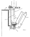
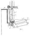
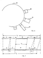
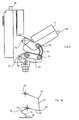
- a main peculiar feature of the present invention lies in the use of pairs of half-moulds adapted to blow mould preforms 1 in view of converting them into finished containers 7, wherein said half-moulds are essentially arranged as illustrated in Figures 1, 2 and 6 showing respectively a schemancal side vertical-section view of a pair of half-moulds in a partially open state, a schematical side vertical-section view of the same half-moulds m an almost fully open state, and a schematical top view of the arrangement of the moulds 24, 25, 26 according to the present invention in a fully open state, as in the case of the moulds 24 and 25, and a fully closed state, as m the case of the mould 26.
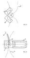
- FIG. 3 a look should be taken at the illustrations appearing in Figures 3 and 4.
- the illustration in Figure 3 can be seen to show, in an extremely schematical manner, a top view of the path a followed by the preform, which is then moulded into a finished container, with respect to the two half-moulds 21 and 22 according to the prior art, and therefore both movable, as shown in an open state thereof.
- said path a must include a deep sloping pattern in order to enable the preform to first slide into the half-moulds and then move out therefrom as a finished container.
- the illustration appeanng in Figure 4 shows, again in a schematical manner, a corresponding top view of the path b followed by the preform, which is then moulded into a finished container, with respect to the fixed half-mould 2 and the moving half-mould 4.
- this illustration does not fail to immediately stress the point that the path b of the preform runs along an arc of circumference without any apparent diversion, or anyway a curvilinear trajectory without any point of inflection that is likely to slow down the movement of the preform/container along the path thereof and to add to the complexity of the construction of the motion control organs.
- the line portions indicated at H, L, M, P and R in the diagram of Figure 7 respectively show the preform insertion time, the half-mould closing time, the blow moulding time (dashed line), the half-mould re-opening time, and the finished container removal time, according to the pnor-art
- the opening phase P' of said moving half-mould is carried out Even in this case, the possibility exists for the subsequent removal phase R' of the finished container to be caused to start earlier, by a time T 1 , before the mould is fully open, so that this partial overlapping of the opening phase P' of the moving half-mould and the removal phase R' of the finished blow-moulded container again brings about a further reduction in the overall cycle time by such a period during which said phases are so overlapping, ie. by the above cited time T 1 .
- a further advantageous improvement of the present invention lies in providing an appropriately curved guide element 15, illustrated in Figures 4 and 5, arranged in a stable manner in such a position as to be able to intercept the path of the preform neck from the trajectory b, and to assist it in its movement of insertion in the respective cavity of the corresponding fixed half-mould 2.
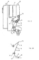
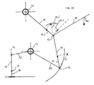
- Figures 8 through to 12 As far as the technical improvements in the organs controlling the movement of the moving half-mould are concerned, reference should be made to Figures 8 through to 12, as well as the corresponding schematics appearing in Figures 8A through to 12A. The latter can be seen to symbolically represent the fundamental points of application of the action and reaction forces on the organs of the plant, the vectors representing such forces, and the direction of action thereof.
- said actuation organs of the moving half-mould 4 comprise:
- the fulcra F1 and F2 of said first class lever and said third class lever, respectively, are applied pivotally on respective distinct points of a structure 60 that is integral withor firmly joined to said fixed half-moulds, furthermore, said moving half-mould 4 is applied on the arm 56 of said third class lever opposite to the related fulcrum F2 with respect to the corresponding power point P2.
- the second extreme end 57 of said actuating member 51 is adapted to be movably actuated by a moving member 58 on a plane that is orthogonal to the axis of rotation of the fulcrum F1 of said first class lever.
- V2,2 in the Figure is oriented towards F2 and acts so as to only compress the related arm 55, with practically no effect at all within the overall geometry, whereas the other component V2,3 is radial with respect to said arm 55 and therefore acts on the arm 56 supporting the half-mould 4, in such a manner as to cause said third class lever to rotate, thereby causing said moving half-mould to close
- Figures 9 through to 11 illustrate subsequent dispositions of the whole assembly of said levers and said connecting and actuating members, along with the respective vectors, corresponding to some subsequent positions of said moving half-mould 4 as it is moved into closing. They are anyway readily understandable by all those skilled in the art, so that no further explanation needs to be given here in this connection.
- Figures 12 and 12A represent the situation when the moving half-mould is fully closed. This is a quite particular situation since, further to representing a kind of end-of-stroke point, it also represents the condition in which the "toggle effect" shows up in all of its effectiveness. In other words, this is the condition in which the clamping force of said half-mould reaches its peak, ie. is maximized, while the angular displacement of said half-mould is at a minimum. Use is anyway made also of other means, further to this fact, in order to ensure a fully stable clamping of said half-mould.
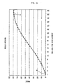
- Figure 14 can be noticed to emphasize how, in comspondence of the portion of curve indicated at M, at a certain progressive displacement of the device or rolling pin 58, whose scale in the lower portion of the Figure is a linear one, a rotation is obtained with a progressively decreasing increment of the angle between the members 54 and 55 until an angle of 0° is eventually reached between said members 54 and 55 in correspondence of a value of approx. 1 in the abscissa.
- Such a moving pattern of said half-mould translates into a number of significant practical advantages, ie. a noticeable reduction in vibrations, the prevention of the moving half-mould from bumping when moving into its end-of-stroke positions, and the possibility for said moving device to be actuated with the help of simple, reliable and accurate means that are furthermore durable, ie. well resistant to wear-down since they are not subject to the action of "forces".
- the continuous operation of the described assembly for altematingly opening and closing the moving half-mould can be obtained through a corresponding to-and-fro movement of the moving device or rolling pin 58, wherein such a movement can be easily obtained by means of a continuously rotating cam device adapted to control the movement and the position of said rolling pin in full synchrony with all other devices, mechanisms and actuators that altogether ensure the various phases for opening the half-mould, introducing the preform, closing the half-mould, blow moulding said preform, opening the half-mould and simultaneous removal of the finished container.
- a further advantage of the present invention denves from the fact that if, as just stated above, the alternating to-and-fro movement of the moving device or rolling pin 58 is actuated by two rotating cams, preferably on the same vertical axis of rotation of the carousel 10 in Figure 6, the limited weardown effect that unavoidably takes place between the actuating surfaces of said rotating cams and said rolling pin has only a very limited impact on the opening and closing accuracy of the moulds.
- This fact brings about the remarkable benefit deriving from the possibility for the maintenace or re-adjustment of said cams and therewith associated organs to be camed out at quite extended intervals, without incurring any loss in processing precision.
Landscapes
- Engineering & Computer Science (AREA)
- Manufacturing & Machinery (AREA)
- Mechanical Engineering (AREA)
- Moulds For Moulding Plastics Or The Like (AREA)
- Blow-Moulding Or Thermoforming Of Plastics Or The Like (AREA)
- Processing And Handling Of Plastics And Other Materials For Molding In General (AREA)
- Medical Preparation Storing Or Oral Administration Devices (AREA)
- Lining Or Joining Of Plastics Or The Like (AREA)
- Polyesters Or Polycarbonates (AREA)
- Extrusion Moulding Of Plastics Or The Like (AREA)
Claims (13)
- Appareil pour mouler par extrusion-soufflage des corps en matière plastique creux, comportant :une pluralité de paires de demi-moules pouvant être réunis mutuellement capables d'être ouverts et fermés, reliés à un appareil rotatif approprié (10) supportant lesdits demi-moules,des dispositifs de support pour supporter les préformes qui correspondent auxdits demi-moules,un mécanisme d'alimentation de préforme adapté pour alimenter une séquence ordonnée de préformes maintenues à une température de moulage par extrusion-soufflage appropriée dans les paires respectives de demi-moules associées audit appareil rotatif, qui sont dans ce but maintenues dans leur position ouverte,un dispositif de récupération adapté pour enlever le conteneur fini à partir de la paire respective de demi-moules après son ouverture,un mécanisme d'ouverture et de fermeture adapté pour fermer les demi-moules après le passage de ceux-ci à travers la position du mécanisme d'alimentation de préforme, et pour les ouvrir avant le passage de ceux-ci à travers la position du mécanisme d'enlèvement de conteneur fini, caractérisé en ce quelesdites paires de demi-moules sont constituées d'un demi-moule fixe (2) et d'un demi-moule mobile (4) qui est capable d'être ouvert à partir dudit demi-moule fixe, et fermé contre celui-ci, lesdits demi-moules fixes (2) étant agencés dans une position sensiblement verticale, et le demi-moule mobile respectif (4) étant adapté pour être fermé en accomplissant un déplacement sensiblement rotatif autour d'un axe de rotation horizontal, caractérisé en ce que ledit mécanisme d'ouverture et de fermeture d'un quelconque desdits demi-moules mobiles (4) comporte :un levier de première classe (52, 53) et un levier de troisième classe (55, 56),une structure (60) associée de manière ferme auxdits demi-moules fixes (2),un élément de connexion (54) qui relie le point de résistance (R1) dudit levier de première classe avec le point de puissance (P2) dudit levier de troisième classe, lesdits points de résistance et de puissance étant connectés de manière pivotante aux extrémités extrêmes dudit élément de connexion,un élément d'actionnement (51) muni de deux extrémités extrêmes, dont la première extrémité extrême est connectée au point de puissance (P1) dudit levier de première classe (52, 53),les points d'appui (F1, F2) dudit levier de première classe et dudit levier de troisième classe étant appliqués de manière pivotante sur des points distincts respectifs de ladite structure (60) associés de manière ferme auxdits demi-moules fixes, etledit demi-moule mobile étant appliqué sur le bras (56) dudit levier de troisième classe qui est opposé au point d'appui concerné (F2) par rapport au point de puissance correspondant (P2).
- Appareil selon la revendication 1, caractérisé en ce que la seconde partie extrême (57) dudit élément d'actionnement (51) est adaptée pour être poussée par un dispositif de déplacement (58) en déplacement sur un plan orthogonal par rapport à l'axe de rotation du point d'appui (F1) dudit levier de première classe.
- Appareil selon la revendication 1 ou 2, caractérisé en ce que lesdits leviers et lesdits éléments de connexion et d'actionnement sont adaptés pour se déplacer entre deux positions extrêmes respectives, positions dans lesquelles une première desdites positions extrêmes correspond à la position entièrement ouverte desdits demi-moules mobiles, tandis que l'autre desdites positions extrêmes correspond à la position entièrement fermée dudit demi-moule mobile.
- Appareil selon la revendication 3, caractérisé en ce que lorsque ladite seconde position extrême (57) dudit élément d'actionnement est entraínée dans le sens de démarrage du déplacement de fermeture dudit demi-moule mobile (4) à partir de sa position entièrement ouverte, le vecteur (V1) de la force transmise à partir dudit point de résistance (R1) dudit levier de première classe audit élément de connexion (54) a une composante (V2) dans la direction dudit élément de connexion qui, lorsqu'elle est appliquée sur ledit point de puissance dudit levier de troisième classe, a à son tour une seconde composante respective (V2, 3) qui est orientée de manière à induire une rotation dudit levier de troisième classe dans la direction de fermeture dudit demi-moule mobile.
- Appareil selon l'une quelconque des revendications 1 à 4, caractérisé en ce que dans ladite position entièrement fermée dudit demi-moule mobile (4), ledit point de puissance (P2) et ledit point d'appui (F1) dudit levier de troisième classe, de même que ledit point de résistance (R1) dudit levier de première classe sont alignés, ou bien les axes de rotation respectifs sont parallèles et se trouvent sur le même plan.
- Appareil selon l'une quelconque des revendications précédentes, caractérisé en ce que ledit dispositif mobile (58) est adapté pour être entraíné dans un déplacement en va et vient entre deux positions extrêmes qui correspondent aux conditions dans lesquelles ledit demi-moule mobile est entièrement ouvert et entièrement fermé, respectivement, par l'intermédiaire de dispositif de came tournant autour d'un axe qui est orthogonal aux axes de rotation desdits deux leviers.
- Appareil selon l'une quelconque des revendications précédentes, caractérisé en ce que dans ladite position entièrement fermée de celui-ci, un dispositif de retenue est fourni, adapté pour empêcher ledit demi-moule mobile (4) de tourner davantage au-delà de ladite position entièrement fermée.
- Appareil selon l'une quelconque des revendications précédentes, caractérisé en ce que des moyens pouvant être actionnés de manière sélective sont fournis, qui sont adaptés pour empêcher ledit demi-moule mobile de tourner en arrière vers la position ouverte à partir de ladite position entièrement fermée.
- Appareil selon l'une quelconque des revendications précédentes, caractérisé en ce que dans la position d'ouverture maximum dudit demi-moule mobile, ledit point de puissance (P1) dudit levier de première classe (52, 53) est aligné avec ladite seconde partie extrême (57) dudit élément d'actionnement (51) et avec ledit élément mobile (58).
- Appareil selon la revendication 9, caractérisé en ce que ledit élément mobile (58) n'est autorisé à être traíné que le long d'un déplacement de translation rectiligne.
- Appareil selon la revendication 10, caractérisé en ce que ledit déplacement de translation rectiligne est orthogonal à la direction de l'alignement parmi :ledit point de puissance (P1)ladite seconde partie extrême (57) dudit élément d'actionnement (51)et ledit élément mobile (58), lorsque ledit demi-moule mobile est dans la position d'ouverture maximum.
- Appareil selon l'une quelconque des revendications 9 à 11, caractérisé en ce qu'il comporte deux leviers à genouillère différents (51, 57, 58) (53, R1, 54).
- Appareil selon la revendication 12, caractérisé en ce qu'un premier desdits leviers à genouillère (51, 57, 58) est entièrement étendu lorsque le demi-moule est entièrement ouvert, et l'autre levier à genouillère (53, R1, 54) est entièrement étendu lorsque le demi-moule mobile est entièrement fermé.
Applications Claiming Priority (3)
| Application Number | Priority Date | Filing Date | Title |
|---|---|---|---|
| IT1998PN000042A IT1305267B1 (it) | 1998-06-03 | 1998-06-03 | Impianto perfezionato per la produzione di contenitori in resinatermoplastica. |
| ITPN980042 | 1998-06-03 | ||
| PCT/EP1999/003397 WO1999062692A1 (fr) | 1998-06-03 | 1999-05-17 | Ameliorations se rapportant a un appareil pour fabriquer des recipients en un materiau thermoplastique |
Publications (2)
| Publication Number | Publication Date |
|---|---|
| EP1084020A1 EP1084020A1 (fr) | 2001-03-21 |
| EP1084020B1 true EP1084020B1 (fr) | 2004-07-14 |
Family
ID=11395388
Family Applications (1)
| Application Number | Title | Priority Date | Filing Date |
|---|---|---|---|
| EP99924997A Expired - Lifetime EP1084020B1 (fr) | 1998-06-03 | 1999-05-17 | Ameliorations se rapportant a un appareil pour fabriquer des recipients en un materiau thermoplastique |
Country Status (13)
| Country | Link |
|---|---|
| US (1) | US6390802B1 (fr) |
| EP (1) | EP1084020B1 (fr) |
| JP (1) | JP2002516769A (fr) |
| CN (1) | CN1144666C (fr) |
| AT (1) | ATE270951T1 (fr) |
| AU (1) | AU744651B2 (fr) |
| BR (1) | BR9910881B1 (fr) |
| DE (1) | DE69918692T2 (fr) |
| ES (1) | ES2221747T3 (fr) |
| IT (1) | IT1305267B1 (fr) |
| RU (1) | RU2201867C2 (fr) |
| TR (1) | TR200003546T2 (fr) |
| WO (1) | WO1999062692A1 (fr) |
Cited By (3)
| Publication number | Priority date | Publication date | Assignee | Title |
|---|---|---|---|---|
| DE102004057102A1 (de) * | 2004-11-26 | 2006-06-01 | Krones Ag | Formblasmaschine |
| DE202004021865U1 (de) | 2004-11-26 | 2012-01-18 | Krones Ag | Formblasmaschine |
| DE202004021863U1 (de) | 2004-11-26 | 2012-01-18 | Krones Aktiengesellschaft | Formblasmaschine |
Families Citing this family (21)
| Publication number | Priority date | Publication date | Assignee | Title |
|---|---|---|---|---|
| IT1311703B1 (it) * | 1999-07-23 | 2002-03-19 | Sipa Spa | Impianto ad alta efficienza di soffiaggio di preforme |
| RU2172247C1 (ru) * | 2000-09-27 | 2001-08-20 | Закрытое акционерное общество "АВТО-ЭЛЬФ" | Установка для изготовления пустотелых изделий |
| US6749419B2 (en) * | 2002-06-13 | 2004-06-15 | Pechiney Emballage Flexible Europe | Mold clamping apparatus |
| ITRM20040107A1 (it) | 2004-03-02 | 2004-06-02 | Sipa Societa Industrializzazio | Dispositivo e metodo di condizionamento di oggetti in plastica. |
| ITRM20040163A1 (it) * | 2004-03-30 | 2004-06-30 | Sipa Societa Industrializzazio | Apparato di stampaggio per soffiaggio di oggetti in plastica. |
| FR2881678B1 (fr) * | 2005-02-08 | 2009-04-24 | Sidel Sas | Procede de commande d'ouverture et de fermeture d'un moule de soufflage et dispositif de soufflage agence pour sa mise en oeuvre |
| DE102005017540A1 (de) * | 2005-04-16 | 2006-10-26 | Sig Technology Ltd. | Verfahren und Vorrichtung zur Blasformung von Behältern |
| DE102005034541A1 (de) * | 2005-07-23 | 2007-02-01 | Sig Technology Ltd. | Verfahren und Vorrichtung zur Blasformung von Behältern |
| FR2912952B1 (fr) * | 2007-02-27 | 2013-08-16 | Sidel Participations | Dispositif de moulage pour la fabrication de recipients en materiau thermoplastique |
| DE102007022638A1 (de) * | 2007-05-15 | 2008-11-20 | Sig Technology Ag | Vorrichtung zur Blasformung von Behältern |
| DE102008021526A1 (de) * | 2008-04-30 | 2009-11-05 | Krones Ag | Vorrichtung zum Expandieren von Kunststoffbehältnissen |
| JP5340694B2 (ja) * | 2008-11-07 | 2013-11-13 | 日精エー・エス・ビー機械株式会社 | ロータリ型ブロー成形装置 |
| EP2335903A4 (fr) * | 2008-09-12 | 2015-07-01 | Nissei Asb Machine Co Ltd | Dispositif rotatif de moulage par soufflage |
| FR2969955B1 (fr) * | 2011-01-04 | 2013-02-01 | Serac Group | Dispositif de soufflage de recipients |
| DE102011007280A1 (de) | 2011-04-13 | 2012-10-18 | Krones Aktiengesellschaft | Behälterbehandlungsmaschine und Verfahren zur Behälterbehandlung |
| DE102011079078A1 (de) | 2011-07-13 | 2013-01-17 | Krones Ag | Einsternzuführung für Behandlungsmaschinen |
| ITUB20160870A1 (it) * | 2016-02-19 | 2017-08-19 | Sipa Progettazione Automaz | Stampo di soffiaggio |
| CN109774105B (zh) * | 2018-12-10 | 2020-10-20 | 德玛克(长兴)注塑系统有限公司 | 一种开合模导轨的曲线轨迹生成方法 |
| USD1003725S1 (en) | 2021-09-03 | 2023-11-07 | Graham Packaging Company, L.P. | Container |
| USD1010454S1 (en) | 2021-09-03 | 2024-01-09 | Graham Packaging Company, L.P. | Container |
| UA154936U (uk) * | 2023-06-27 | 2024-01-03 | Олександр Володимирович Суворов | Механізм змикання прес-форми установки для виготовлення пет-тари |
Family Cites Families (10)
| Publication number | Priority date | Publication date | Assignee | Title |
|---|---|---|---|---|
| US2750625A (en) * | 1950-09-25 | 1956-06-19 | Royal Mfg Company Inc | Apparatus for continuous moulding of synthetic resins |
| FR1430899A (fr) | 1964-09-10 | 1966-03-11 | Tuboplast France | Machine pour la fabrication en continu de corps creux |
| BE656716A (fr) | 1964-12-07 | 1965-06-08 | ||
| US3624672A (en) * | 1968-06-13 | 1971-11-30 | Phillips Petroleum Co | Molding of cellular objects |
| DE1909050C3 (de) * | 1969-02-22 | 1988-03-24 | Klöckner-Werke AG, 4100 Duisburg | Formenstraße in einer Anlage zur Verarbeitung von schäumenden Mehrkomponenten-Kunststoffen |
| DE2146245C3 (de) * | 1971-09-16 | 1975-09-04 | Desma-Werke Gmbh, 2807 Uesen | Formwerkzeuge, Insbesondere zum Herstellen von Formungen aus Polyurethan |
| FR2235788B1 (fr) * | 1973-07-06 | 1976-05-07 | Solvay | |
| FR2413196A1 (fr) * | 1977-12-27 | 1979-07-27 | Yoshino Kogyosho Co Ltd | Machine de moulage avec orientation par soufflage |
| US4752206A (en) * | 1987-04-06 | 1988-06-21 | Johnson Service Company | Take-out assembly for blow molding machine |
| US5225216A (en) * | 1991-06-13 | 1993-07-06 | Nrm Corporation | Mold opening apparatus for blow molding machine |
-
1998
- 1998-06-03 IT IT1998PN000042A patent/IT1305267B1/it active
-
1999
- 1999-05-17 BR BRPI9910881-0A patent/BR9910881B1/pt not_active IP Right Cessation
- 1999-05-17 WO PCT/EP1999/003397 patent/WO1999062692A1/fr not_active Ceased
- 1999-05-17 TR TR2000/03546T patent/TR200003546T2/xx unknown
- 1999-05-17 CN CNB998065137A patent/CN1144666C/zh not_active Expired - Lifetime
- 1999-05-17 EP EP99924997A patent/EP1084020B1/fr not_active Expired - Lifetime
- 1999-05-17 JP JP2000551933A patent/JP2002516769A/ja active Pending
- 1999-05-17 AT AT99924997T patent/ATE270951T1/de active
- 1999-05-17 ES ES99924997T patent/ES2221747T3/es not_active Expired - Lifetime
- 1999-05-17 US US09/701,614 patent/US6390802B1/en not_active Expired - Lifetime
- 1999-05-17 RU RU2000133312/12A patent/RU2201867C2/ru not_active IP Right Cessation
- 1999-05-17 DE DE69918692T patent/DE69918692T2/de not_active Expired - Lifetime
- 1999-05-17 AU AU41445/99A patent/AU744651B2/en not_active Ceased
Cited By (7)
| Publication number | Priority date | Publication date | Assignee | Title |
|---|---|---|---|---|
| DE102004057102A1 (de) * | 2004-11-26 | 2006-06-01 | Krones Ag | Formblasmaschine |
| WO2006056437A2 (fr) | 2004-11-26 | 2006-06-01 | Krones Ag | Machine de moulage par soufflage |
| US7708549B2 (en) | 2004-11-26 | 2010-05-04 | Krones Ag | Blow molding machine |
| DE202004021755U1 (de) | 2004-11-26 | 2010-09-30 | Krones Ag | Formblasmaschine |
| DE202004021865U1 (de) | 2004-11-26 | 2012-01-18 | Krones Ag | Formblasmaschine |
| DE202004021863U1 (de) | 2004-11-26 | 2012-01-18 | Krones Aktiengesellschaft | Formblasmaschine |
| DE102004057102B4 (de) * | 2004-11-26 | 2021-01-14 | Krones Aktiengesellschaft | Formblasmaschine |
Also Published As
| Publication number | Publication date |
|---|---|
| WO1999062692A1 (fr) | 1999-12-09 |
| BR9910881A (pt) | 2001-02-28 |
| BR9910881B1 (pt) | 2008-11-18 |
| US6390802B1 (en) | 2002-05-21 |
| JP2002516769A (ja) | 2002-06-11 |
| EP1084020A1 (fr) | 2001-03-21 |
| ATE270951T1 (de) | 2004-07-15 |
| TR200003546T2 (tr) | 2001-04-20 |
| IT1305267B1 (it) | 2001-04-19 |
| AU4144599A (en) | 1999-12-20 |
| DE69918692D1 (de) | 2004-08-19 |
| ITPN980042A1 (it) | 1999-12-03 |
| CN1144666C (zh) | 2004-04-07 |
| ES2221747T3 (es) | 2005-01-01 |
| AU744651B2 (en) | 2002-02-28 |
| DE69918692T2 (de) | 2005-01-13 |
| CN1302251A (zh) | 2001-07-04 |
| RU2201867C2 (ru) | 2003-04-10 |
Similar Documents
| Publication | Publication Date | Title |
|---|---|---|
| EP1084020B1 (fr) | Ameliorations se rapportant a un appareil pour fabriquer des recipients en un materiau thermoplastique | |
| US8100688B2 (en) | Device for blow molding containers | |
| AU775749B2 (en) | Rotary stretch blow moulding machine comprising a magnetically controlled stretch rod | |
| JPH0439023A (ja) | 把手付合成樹脂容器の製造方法及び装置 | |
| KR920002362B1 (ko) | 사출연신취입 성형기에 있어서의 온조(溫調)취입 성형장치 | |
| US20090065980A1 (en) | Method and Device for Blow-Molding Containers | |
| RU2000133312A (ru) | Усовершенствование устройства для производства тары из термопластичных материалов | |
| EP3858581A1 (fr) | Machine de moulage par soufflage et procédé de commande de machine de moulage par soufflage | |
| US5238389A (en) | Apparatus for preparing a hollow plastic article | |
| US4822275A (en) | Apparatus for opening and closing mold halves | |
| JPH0679773A (ja) | 射出延伸吹込成形方法及び装置 | |
| US4379688A (en) | Oriented injection blow molded container production | |
| US5759593A (en) | Apparatus for blow-molding and releasing hollow articles | |
| JP4368893B2 (ja) | 機械制御延伸ロッド付きの延伸ブロー成形機 | |
| EP0499136A2 (fr) | Tige d'allongement sous action servo-électrique, pour une machine de moulage par soufflage | |
| JP4105636B2 (ja) | 二軸配向型熱可塑性樹脂容器製造用の一体成形型および一体成形型を用いた二軸配向型熱可塑性樹脂容器の製造方法 | |
| US11623383B2 (en) | Blowing or stretch-blowing machine for bottles made of polymer material | |
| US4251203A (en) | Apparatus for producing articles from thermoplastic parisons | |
| AU2011312400B2 (en) | Angle link pivot bracket for wheel | |
| US4290995A (en) | Method of producing articles from thermoplastic parisons | |
| JP2005516812A5 (fr) | ||
| JPH06102357B2 (ja) | 予備成形品の搬送装置 | |
| JP5784238B2 (ja) | パリソンまたはパリソンから製造される容器のための保持装置 | |
| CN118488889A (zh) | 通过吹制或拉制吹制模制热塑性材料制容器的模制装置 | |
| MXPA99012019A (en) | Method and installation for making containers by blowing thermoplastic blanks |
Legal Events
| Date | Code | Title | Description |
|---|---|---|---|
| PUAI | Public reference made under article 153(3) epc to a published international application that has entered the european phase |
Free format text: ORIGINAL CODE: 0009012 |
|
| 17P | Request for examination filed |
Effective date: 20000919 |
|
| AK | Designated contracting states |
Kind code of ref document: A1 Designated state(s): AT DE ES FR GB IT |
|
| GRAP | Despatch of communication of intention to grant a patent |
Free format text: ORIGINAL CODE: EPIDOSNIGR1 |
|
| GRAS | Grant fee paid |
Free format text: ORIGINAL CODE: EPIDOSNIGR3 |
|
| GRAA | (expected) grant |
Free format text: ORIGINAL CODE: 0009210 |
|
| AK | Designated contracting states |
Kind code of ref document: B1 Designated state(s): AT DE ES FR GB IT |
|
| REG | Reference to a national code |
Ref country code: GB Ref legal event code: FG4D |
|
| REF | Corresponds to: |
Ref document number: 69918692 Country of ref document: DE Date of ref document: 20040819 Kind code of ref document: P |
|
| REG | Reference to a national code |
Ref country code: ES Ref legal event code: FG2A Ref document number: 2221747 Country of ref document: ES Kind code of ref document: T3 |
|
| ET | Fr: translation filed | ||
| PLBE | No opposition filed within time limit |
Free format text: ORIGINAL CODE: 0009261 |
|
| STAA | Information on the status of an ep patent application or granted ep patent |
Free format text: STATUS: NO OPPOSITION FILED WITHIN TIME LIMIT |
|
| 26N | No opposition filed |
Effective date: 20050415 |
|
| PG25 | Lapsed in a contracting state [announced via postgrant information from national office to epo] |
Ref country code: IT Free format text: LAPSE BECAUSE OF NON-PAYMENT OF DUE FEES Effective date: 20090517 |
|
| PGRI | Patent reinstated in contracting state [announced from national office to epo] |
Ref country code: IT Effective date: 20110616 |
|
| PGFP | Annual fee paid to national office [announced via postgrant information from national office to epo] |
Ref country code: GB Payment date: 20150916 Year of fee payment: 17 |
|
| REG | Reference to a national code |
Ref country code: FR Ref legal event code: PLFP Year of fee payment: 18 |
|
| GBPC | Gb: european patent ceased through non-payment of renewal fee |
Effective date: 20160517 |
|
| REG | Reference to a national code |
Ref country code: FR Ref legal event code: PLFP Year of fee payment: 19 |
|
| PG25 | Lapsed in a contracting state [announced via postgrant information from national office to epo] |
Ref country code: GB Free format text: LAPSE BECAUSE OF NON-PAYMENT OF DUE FEES Effective date: 20160517 |
|
| REG | Reference to a national code |
Ref country code: FR Ref legal event code: PLFP Year of fee payment: 20 |
|
| PGFP | Annual fee paid to national office [announced via postgrant information from national office to epo] |
Ref country code: ES Payment date: 20180601 Year of fee payment: 20 Ref country code: DE Payment date: 20180522 Year of fee payment: 20 |
|
| PGFP | Annual fee paid to national office [announced via postgrant information from national office to epo] |
Ref country code: AT Payment date: 20180525 Year of fee payment: 20 Ref country code: FR Payment date: 20180529 Year of fee payment: 20 Ref country code: IT Payment date: 20180522 Year of fee payment: 20 |
|
| REG | Reference to a national code |
Ref country code: DE Ref legal event code: R071 Ref document number: 69918692 Country of ref document: DE |
|
| REG | Reference to a national code |
Ref country code: AT Ref legal event code: MK07 Ref document number: 270951 Country of ref document: AT Kind code of ref document: T Effective date: 20190517 |
|
| REG | Reference to a national code |
Ref country code: ES Ref legal event code: FD2A Effective date: 20200723 |
|
| PG25 | Lapsed in a contracting state [announced via postgrant information from national office to epo] |
Ref country code: ES Free format text: LAPSE BECAUSE OF EXPIRATION OF PROTECTION Effective date: 20190518 |