EP1084037B1 - Dispositif de revetement pour imprimante a jet d'encre - Google Patents
Dispositif de revetement pour imprimante a jet d'encre Download PDFInfo
- Publication number
- EP1084037B1 EP1084037B1 EP99928584A EP99928584A EP1084037B1 EP 1084037 B1 EP1084037 B1 EP 1084037B1 EP 99928584 A EP99928584 A EP 99928584A EP 99928584 A EP99928584 A EP 99928584A EP 1084037 B1 EP1084037 B1 EP 1084037B1
- Authority
- EP
- European Patent Office
- Prior art keywords
- roll
- coating material
- ink jet
- printing substrate
- printing
- Prior art date
- Legal status (The legal status is an assumption and is not a legal conclusion. Google has not performed a legal analysis and makes no representation as to the accuracy of the status listed.)
- Expired - Lifetime
Links
Images


Classifications
-
- B—PERFORMING OPERATIONS; TRANSPORTING
- B41—PRINTING; LINING MACHINES; TYPEWRITERS; STAMPS
- B41J—TYPEWRITERS; SELECTIVE PRINTING MECHANISMS, i.e. MECHANISMS PRINTING OTHERWISE THAN FROM A FORME; CORRECTION OF TYPOGRAPHICAL ERRORS
- B41J11/00—Devices or arrangements of selective printing mechanisms, e.g. ink-jet printers or thermal printers, for supporting or handling copy material in sheet or web form
- B41J11/0015—Devices or arrangements of selective printing mechanisms, e.g. ink-jet printers or thermal printers, for supporting or handling copy material in sheet or web form for treating before, during or after printing or for uniform coating or laminating the copy material before or after printing
-
- B—PERFORMING OPERATIONS; TRANSPORTING
- B41—PRINTING; LINING MACHINES; TYPEWRITERS; STAMPS
- B41J—TYPEWRITERS; SELECTIVE PRINTING MECHANISMS, i.e. MECHANISMS PRINTING OTHERWISE THAN FROM A FORME; CORRECTION OF TYPOGRAPHICAL ERRORS
- B41J2/00—Typewriters or selective printing mechanisms characterised by the printing or marking process for which they are designed
- B41J2/005—Typewriters or selective printing mechanisms characterised by the printing or marking process for which they are designed characterised by bringing liquid or particles selectively into contact with a printing material
- B41J2/01—Ink jet
Definitions
- Drop-on-demand ink jet printers use thermal energy to produce a vapor bubble in an ink-filled chamber to expel a droplet.
- a thermal energy generator or heating element usually a resistor, is located in the chamber on a heater chip near a discharge nozzle.
- a plurality of chambers, each provided with a single heating element, are provided in the printer's printhead.
- the printhead typically comprises the heater chip and a nozzle plate having a plurality of the discharge nozzles formed therein.
- the printhead forms part of an ink jet print cartridge which also comprises an ink-filled container.
- Ink jet printers have typically suffered from two major shortcomings. First, optical density of a printed image varies greatly with the print media or substrate being printed upon. Second, ink drying time is excessive.
- JPO 8072227 discloses coating means for applying a pretreatment solution to the printing surface of the recording paper.
- US 5,628,827 discloses a coater including a doctor blade for applying coating fluid to a moving surface.
- Heating stations positioned before, coincident with and after the print zone can improve optical density and drying time, but at the expense of power consumption and machine complexity. Hence, this solution has not been found desirable.
- an ink jet printer comprising:
- the coating apparatus is positioned before the ink jet printing device. It is also preferred that the coating material have a high viscosity such that only a minimum amount of water is introduced onto the substrate. Typically, the functionality of the coating material is not diminished by the addition of water to the coating material. However, when the substrate is formed from a paper material, the additional water applied to the substrate exacerbates substrate curl and cockle.
- the coating apparatus is capable of operating over a wide range of speeds while maintaining a nearly constant rate of application.
- a process for printing information on a printing substrate comprising the steps of:
- Fig. 1 is a perspective view of a coating apparatus constructed in accordance with a first embodiment of the present invention
- Fig. 2 is a side view, partially broken away, of an ink jet printer including the coating apparatus illustrated in Fig. 1;
- Fig. 3 is an enlarged side view of the third roller and doctor blade illustrated in Fig. 2 and taken from a first side of a printer;
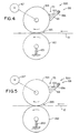
- Fig. 4 is a side view of a portion of a coating apparatus constructed in accordance with a second embodiment of the present invention, wherein this view is taken from a side of a printer which is opposite to the one illustrated in Figs. 2 and 3; and
- Fig. 5 is a side view of a portion of a coating apparatus constructed in accordance with a third embodiment of the present invention, wherein this view is taken from a side of a printer which is opposite to the one illustrated in Figs. 2 and 3.
- the printer 10 comprises an ink jet printer apparatus 20 located within a housing 30.
- the printer apparatus 20 includes an ink jet print cartridge 22 (also referred to herein as an ink jet printing device) supported in a carrier 23 which, in turn, is supported on a guide rail 26.
- a drive mechanism including a drive belt 28 is provided for effecting reciprocating movement of the carrier 23 and the print cartridge 22 back and forth along the guide rail 26.
- the print cartridge 22 moves back and forth, it ejects ink droplets onto a printing substrate 12 provided below it.
- Substrates 12 capable of being printed upon by the printer 10 include commercially available plain office paper, specialty papers, envelopes, transparencies, labels, card stock and the like.
- the ink jet printer apparatus 20 further comprises a driver circuit 24.
- the circuit 24 provides voltage pulses to resistive heating elements (not shown) located within a printhead (not shown) forming part of the print cartridge 22. Each voltage pulse is applied to one of the heating elements to momentarily vaporize ink in contact with that heating element to form a bubble within a bubble chamber (not shown) in which the heating element is located.
- the function of the bubble is to displace ink within the bubble chamber such that a droplet of ink is expelled from a nozzle (not shown) associated with the bubble chamber.
- the printer housing 30 includes a bottom tray 32 for storing substrates 12 to be printed upon.
- a rotatable feed roller 40 is mounted within the housing 30 and positioned over the tray 32. Upon being rotated by a conventional drive device (not shown), the roller 40 grips the uppermost substrate 12 and feeds it along an initial portion of a substrate feed path to a coating apparatus 60.
- the initial feed path portion is defined in substantial part by a pair of substrate guides 50.
- the coating apparatus 60 applies a layer of coating material onto at least a portion of a first side 12a of the substrate 12 prior to printing.
- the coating apparatus 60 comprises rotatable first, second and third rolls 62, 64 and 66 and a metering device 68, see Figs. 1 and 2.
- the first roll 62 is formed from aluminum.
- the roll 62 may be formed from a polymeric material, a ceramic material or a different metal.
- the outer surface 62a of the aluminum roll 62 is grit-blasted so as to have a surface roughness of between about 1 and 4 micrometers R a . After grit blasting, the aluminum roll 62 is anodized to harden the outer surface 62a to make it less prone to wear.
- the second roll 64 is mounted within the housing 30 directly above the first roll 62.
- the first and second rolls 62 and 64 define a nip 65 through which the substrate 12 passes.
- the third roll 66 has a textured or rough outer surface 66a and may be made from the same material and grit blasted in essentially the same manner as the first roll 62.
- the third roll 66 is mounted in the housing 30 directly above and in contact with the second roll 64.
- a roll drive 67 comprising an electric motor 67a having a drive shaft 67b.
- a first gear 67c is mounted to the motor drive shaft 67b for rotation with the drive shaft 67b.
- the teeth on the first gear 67c engage teeth on a second gear 66b mounted on the third roll 66 such that rotation of the motor drive shaft 67b effects rotation of the third roll 66.
- a third gear 64b is coupled to the second roll 64 for rotation with the second roll 64. Teeth on the third gear 64b engage the teeth on the second gear 66b such that rotation of the second gear 66b and the third roll 66 effects rotation of the second roll 64.
- the first roll 62 is rotated by frictional contact with the second roll 64.
- Actuation of the roll drive 67 is effected by the driver circuit 24.
- the roll drive 67 effects continuous rotation of the rolls 62, 64 and 66 during a substrate printing operation.
- the speed of rotation of the continuously moving rolls 62, 64 and 66 may vary during the printing of a substrate 12.
- the speed of rotation may vary as a function of the rate at which the substrate 12 is fed past the print cartridge 22.
- the metering device 68 comprises a doctor blade 69 and a coating material supply device 80.
- the coating material supply device 80 is shown only in Fig. 2.
- the doctor blade 69 is mounted on a shaft 69a which, in turn, is mounted to the housing 30, see Fig. 1.
- a torsion spring 69b biases the blade 69 toward the third roll 66, see also Fig. 3.
- the doctor blade 69 includes a rectangularly shaped edge 69c and is positioned such that a corner 69d of the blade edge 69c bears on the outer surface 66a of the roll 66.
- a first side 69e of the doctor blade 69 and a portion 66c of the third roll 66 define a coating material receiving trough 70.
- First and second sealing members 72a and 72b are mounted adjacent to end portions of the third roll 66 and the doctor blade 69 so as to seal off end sections of the trough 70.
- Coating material 100 is provided to the trough 70 by the coating material supply
- the supply device 80 comprises a reservoir 68a containing liquid coating material 100, an electric valve 68b which controls the flow of coating material 100 from the reservoir 68a to the trough 70, conduits 68c which define paths for the coating material 100 to travel from the reservoir 68a to the trough 70 and a conventional fluid level sensor (not shown) for sensing the level of coating material 100 in the trough 70.
- the fluid level sensor generates fluid level signals to the driver circuit 24. Actuation of the valve 68b is controlled by the circuit 24 based upon the signals generated by the fluid level sensor.
- the third roll 66 As the third roll 66 rotates, its non-smooth outer surface 66a carries liquid coating material under the blade 69 in an amount determined primarily by the size of the depressions or valleys formed in the outer surface 66a of the roll 66. Because one comer 69d of the blade 69 contacts the roll 66 rather than a portion of the blade's first side 69e, the amount of coating material carried by the roll 66 under the blade 69 does not change significantly as the rotational speed of the roll 66 varies or as the load of the blade 69 against the roll 66 changes.
- the coating material 100 on the third roll 66 is transferred to the second roll 64.
- the second roll 64 then transfers the coating material to the substrate 12 passing through the nip 65.
- the second roll 64 is formed from a material having a surface energy which allows the liquid coating material to sufficiently spread out on its outer surface 64a such that a substantially uniform layer of coating material 100 is applied by the second roll 64 to the substrate 12.
- the material from which the second roll 64 is formed preferably also has a sufficiently low hardness so that the second roll 64 is capable of conforming to a substantial number of valleys in the substrate 12 such that coating material 100 is transferred to those substrate valleys.
- the outer surface 64a of the second roll 64 is preferably smooth.
- the second roll 64 is formed from a polyurethane, such as a polycaprolactone urethane prepolymer, which is commercially available from Uniroyal Chemical Co. under the product designation "Vibrathane 6060.”
- the second roll 64 is ground and polished to a surface roughness of between about 14 microinches R a to about 17 microinches R a .
- substantially the entire surface of the first side 12a of each substrate 12 is coated with liquid coating material 100.
- liquid coating material 100 Preferably, between about 80 milligrams to about 120 milligrams and most preferably about 100 milligrams of coating material 100 is applied to an 8.5 inch by I 1 inch substrate. It is also contemplated that only a portion of the first side 12a of each substrate 12, such as the portion which is to reccive printed matter, may be coated.
- the coating material is preferably one which is designed to speed penetration of water into the substrate 12 and fix and flocculate the ink colorant on the surface of the substrate 12, thereby improving dry time, optical density and image permanence.
- Example coating materials are set out in co-pending U.S. Patent Application entitles "COATING SYSTEM FOR INK JET APPLICATIONS".
- the coating apparatus 60 is capable of applying a substantially uniform layer of coating material onto a substrate 12, wherein the coating material has a viscosity of between about 50 centipoise and about 5000 centipoise. Higher viscosity coating materials are preferred as they contain less water.
- a pair of first feed rollers 81 and 82 are positioned within the housing 30 between the coating apparatus 60 and the ink jet print cartridge 22. They are incrementally driven by a conventional roller drive device 84 which is controlled by the circuit 24. The first feed rollers 81 and 82 incrementally feed the substrate 12 beneath the print cartridge 22. As noted above, the print cartridge 22 ejects ink droplets onto the substrate 12 as it moves back and forth along the guide rail 26 such that an image is printed on the substrate 12.
- An intermediate substrate guide device 90 comprising a first substantially linear guide 92 and a second generally bowed guide 94 is positioned within the housing 30 along the substrate feed path between the coating apparatus 60 and the first feed rollers 81 and 82.
- the circuit 24 causes the first and second rolls 62 and 64 to move continuously so as to permit the first and second rolls 62 and 64 to apply a substantially uniform layer of coating material 100 onto the substrate 12.
- the circuit 24 also causes the first and second rolls 62 and 64 to rotate at a rotational speed sufficient such that the substrate 12 is fed at a linear speed through the rolls 62 and 64 which is greater than the speed at which the substrate 12 passes through the incrementally driven rollers 81 and 82. Due to the bowed configuration of the guide 94, the substrate 12 is permitted to buckle away from the substrate feed path as it moves out of the coating apparatus 60 and through the first feed rollers 81 and 82.
- a pair of second feed rollers 110 and 112 are positioned within the housing 30 downstream from the print cartridge 22. They are incrementally driven by a conventional roller drive device (not shown) which is controlled by the circuit 24. The feed rollers 110 and 112 cause the printed substrate 12 to move through final substrate guides 114 and 116 to an output tray 34.
- a coating apparatus 200 constructed in accordance with a second embodiment of the present invention, is shown in Fig. 4, wherein like reference numerals indicate like elements.
- the coating apparatus 200 comprises first and second rotatable rolls 162 and 164 and a metering device 68.
- the metering device 68 is substantially the same as the device illustrated in Fig. 2.
- the coating material supply device 80 is not illustrated in Fig. 4.
- the first roll 162 is formed in essentially the same manner and from substantially the same material as the second roll 64 of the Fig. 1 embodiment.
- the second roll 164 is made from the same material and texturized in essentially the same manner as the first and third rolls 62 and 66 of the Fig. 1 embodiment.
- the second roll 164 is mounted within the housing 30 directly above the first roll 162. Springs 163 bias the first roll 162 upwardly toward the second roll 164 so that it contacts the second roll 164.
- the first and second rolls 162 and 164 define a nip 165 through which the substrate 12 passes.
- a roll drive 167 is provided for effecting rotation of the second roll 164.
- the first roll 162 is rotated by frictional contact with the second roll 164.
- Actuation of the roll drive 167 is effected by the driver circuit 24.
- the roll drive 167 effects continuous rotation of the first and second rolls 162 and 164 during the printing of a single substrate 12.
- the speed of rotation of the continuously moving rolls 162 and 164 may vary during a substrate printing operation. For example, it may vary as a function of the rate at which the substrate 12 is fed past the print cartridge 22 by the rollers 81 and 82.
- a coating apparatus 300 constructed in accordance with a third embodiment of the present invention, is shown in Fig. 5, wherein like reference numerals indicate like elements.
- the coating apparatus 300 comprises first and second rotatable rolls 262 and 264 and a metering device 68.
- the metering device 68 is substantially the same as the device illustrated in Fig. 2.
- the coating material supply device 80 is not illustrated in Fig. 5.
- the first roll 262 is made from the same material and texturized in essentially the same manner as the first and third rolls 62 and 66 of the Fig. 1 embodiment.
- the second roll 264 is formed in essentially the same manner and from substantially the same material as the second roll 64 of the Fig. 1 embodiment.
- the second roll 264 is mounted within the housing 30 directly above the first roll 262. Springs 263 bias the first roll 262 upwardly toward the second roll 264 so that it contacts the second roll 264.
- the first and second rolls 262 and 264 define a nip 265 through which the substrate 12 passes.
- a roll drive 267 is provided for effecting rotation of the second roll 264.
- the first roll 262 is rotated by frictional contact with the second roll 264.
- Actuation of the roll drive 267 is effected by the driver circuit 24.
- the roll drive 267 effects continuous rotation of the first and second rolls 262 and 264 during a substrate printing operation.
- the speed of rotation of the continuously moving rolls 262 and 264 may vary during the substrate printing operation. For example, it may vary as a function of the rate at which the substrate 12 is fed past the print cartridge 22 by the rollers 81 and 82.
- the coating apparatus may be positioned downstream from the print cartridge 22. In such an embodiment, the coating apparatus applies a coating material over the ink applied to the substrate 12. It is also contemplated that a non-liquid coating material may be applied by the coating apparatus to the substrate.
Landscapes
- Coating Apparatus (AREA)
- Ink Jet (AREA)
Claims (12)
- Imprimante à jet d'encre, comprenant:caractérisée en ce que:un boítier;un appareil d'impression à jet d'encre disposé à l'intérieur dudit boítier et comprenant un dispositif d'impression à jet d'encre capable d'éjecter des gouttelettes d'encre sur une première face d'un substrat d'impression qui se déplace à travers ledit boítier le long d'un chemin d'alimentation de substrat d'impression; etun appareil de revêtement positionné le long dudit chemin d'alimentation de substrat d'impression et espacé dudit dispositif d'impression, ledit appareil de revêtement appliquant une couche substantiellement uniforme d'une matière de revêtement sur au moins une partie de ladite première face dudit substrat d'impression; dans laquelle ledit appareil de revêtement est positionné avant ledit dispositif d'impression à jet d'encre, et comprend:un premier cylindre rotatif;un deuxième cylindre rotatif positionné à proximité dudit premier cylindre et définissant avec ledit premier cylindre une fente à travers laquelle ledit substrat d'impression passe;ledit dispositif de dosage comprenant:ledit premier cylindre présente une surface extérieure texturée en aluminium sablé;ledit deuxième cylindre est constitué d'une matière polymère; etun dispositif de dosage appliquant une couche de matière de revêtement sur un premier desdits premier et deuxième cylindres, qui transfère à son tour ladite matière de revêtement sur ledit substrat d'impression;une lame docteur en contact avec ledit un premier cylindre de telle sorte qu'une surface de ladite lame docteur et une partie dudit un premier cylindre définissent une cuve de réception de matière de revêtement; etun dispositif de fourniture de matière de revêtement pour déverser une matière de revêtement dans ladite cuve de réception de matière de revêtement, ladite lame docteur formant une couche essentiellement uniforme de la matière de revêtement à recevoir par ledit cylindre lorsque ledit un premier cylindre est entraíné à tourner.
- Imprimante à jet d'encre suivant la revendication 1, dans laquelle ledit un premier cylindre comprend ledit premier cylindre.
- Imprimante à jet d'encre suivant la revendication 1, dans laquelle ledit un premier cylindre comprend ledit deuxième cylindre.
- Imprimante à jet d'encre suivant l'une quelconque des revendications précédentes, comprenant en outre:un troisième cylindre rotatif présentant une surface extérieure texturée et positionné à proximité dudit deuxième cylindre, et dans laquelleledit dispositif de dosage applique une couche substantiellement uniforme de matière de revêtement liquide sur ledit troisième cylindre, ledit troisième cylindre transférant ladite matière de revêtement sur ledit deuxième cylindre qui transfère à son tour ladite matière de revêtement sur ledit substrat d'impression.
- Imprimante à jet d'encre suivant la revendication 4, dans laquelle ledit troisième cylindre comprend un cylindre en aluminium sablé.
- Imprimante à jet d'encre suivant l'une quelconque des revendications précédentes, dans laquelle ledit deuxième cylindre est constitué d'une matière présentant une énergie de surface qui permet à ladite matière de revêtement liquide d'être suffisamment dispersée de telle sorte qu'une couche substantiellement uniforme de matière de revêtement soit appliquée par ledit deuxième cylindre sur ledit substrat d'impression.
- Imprimante à jet d'encre suivant la revendication 6, dans laquelle ladite matière dont ledit deuxième cylindre est constitué présente une dureté suffisamment basse pour que ledit deuxième cylindre soit capable de se conformer à un nombre substantiel de vallées dans ledit substrat d'impression.
- Imprimante à jet d'encre suivant l'une quelconque des revendications précédentes, comprenant en outre une paire de cylindres d'alimentation positionnés à l'intérieur dudit boítier entre ledit appareil de revêtement et ledit dispositif d'impression à jet d'encre pour faire avancer d'une façon incrémentielle ledit substrat d'impression le long dudit chemin d'alimentation de substrat d'impression au-delà dudit dispositif d'impression à jet d'encre.
- Imprimante à jet d'encre suivant la revendication 8, comprenant en outre un dispositif de guidage de substrat d'impression positionné à l'intérieur dudit boítier entre ledit appareil de revêtement et ladite paire de cylindres d'alimentation et présentant une configuration telle que ledit substrat d'impression est autorisé à s'écarter dudit chemin d'alimentation de substrat d'impression lorsque celui-ci sort dudit appareil de revêtement et passe à travers ladite paire de cylindres d'alimentation.
- Procédé pour imprimer des informations sur un substrat d'impression, comprenant les étapes consistant à:caractérisé en ce quedéplacer un substrat d'impression le long d'un chemin d'alimentation;fournir un appareil de revêtement positionné le long dudit chemin d'alimentation et avant un dispositif d'impression à jet d'encre, et espacé dudit dispositif d'impression à jet d'encre, comprenant:un premier cylindre rotatif; etun deuxième cylindre rotatif positionné à proximité dudit premier cylindre et définissant une fente avec ledit premier cylindre à travers laquelle ledit substrat d'impression passe;faire passer ledit substrat d'impression à travers ladite fente;transférer une matière de revêtement sur ledit substrat d'impression à partir d'un premier desdits premier et deuxième cylindres;appliquer une couche de matière de revêtement sur au moins une partie d'une première face dudit substrat d'impression, et ensuiteéjecter des gouttelettes d'encre à partir d'un dispositif d'impression à jet d'encre sur ladite première face dudit substrat d'impression, de telle sorte que des informations soient imprimées sur ledit substrat;
ledit premier cylindre présente une surface extérieure texturée en aluminium sablé;
ledit deuxième cylindre est constitué d'une matière polymère;
ledit appareil de revêtement comprend une lame docteur en contact avec ledit un premier cylindre de telle sorte qu'une surface de ladite lame docteur et une partie dudit un premier cylindre définissent une cuve de réception de matière de revêtement; et
un dispositif de fourniture de matière de revêtement;
ledit dispositif de fourniture de matière de revêtement déversant une matière de revêtement dans ladite cuve de réception de matière de revêtement;
ladite lame docteur appliquant une couche essentiellement uniforme de matière de revêtement sur un desdits premier et deuxième cylindres lorsque ledit un premier cylindre est entraíné à tourner. - Procédé suivant la revendication 10, dans lequel ladite couche de matière de revêtement est appliquée substantiellement sur la totalité d'une surface de ladite première face dudit substrat d'impression.
- Procédé suivant la revendication 10, dans lequel lesdites gouttelettes d'encre sont uniquement éjectées sur ladite partie de ladite première face dudit substrat d'impression.
Applications Claiming Priority (3)
| Application Number | Priority Date | Filing Date | Title |
|---|---|---|---|
| US96306 | 1998-06-11 | ||
| US09/096,306 US6183079B1 (en) | 1998-06-11 | 1998-06-11 | Coating apparatus for use in an ink jet printer |
| PCT/US1999/013235 WO1999064243A1 (fr) | 1998-06-11 | 1999-06-10 | Dispositif de revetement pour imprimante a jet d'encre |
Publications (3)
| Publication Number | Publication Date |
|---|---|
| EP1084037A1 EP1084037A1 (fr) | 2001-03-21 |
| EP1084037A4 EP1084037A4 (fr) | 2002-01-30 |
| EP1084037B1 true EP1084037B1 (fr) | 2004-09-15 |
Family
ID=22256762
Family Applications (1)
| Application Number | Title | Priority Date | Filing Date |
|---|---|---|---|
| EP99928584A Expired - Lifetime EP1084037B1 (fr) | 1998-06-11 | 1999-06-10 | Dispositif de revetement pour imprimante a jet d'encre |
Country Status (8)
| Country | Link |
|---|---|
| US (1) | US6183079B1 (fr) |
| EP (1) | EP1084037B1 (fr) |
| JP (1) | JP2002517341A (fr) |
| KR (1) | KR20010052708A (fr) |
| CN (1) | CN1314844A (fr) |
| AU (1) | AU4562099A (fr) |
| DE (1) | DE69920214D1 (fr) |
| WO (1) | WO1999064243A1 (fr) |
Families Citing this family (56)
| Publication number | Priority date | Publication date | Assignee | Title |
|---|---|---|---|---|
| JP2003025559A (ja) * | 2001-07-19 | 2003-01-29 | Canon Inc | 液体塗布装置及び画像記録装置 |
| JP4144850B2 (ja) * | 2001-07-19 | 2008-09-03 | キヤノン株式会社 | インク記録済媒体に適応可能な液体塗布装置及びそれを有する画像形成装置 |
| US6706118B2 (en) | 2002-02-26 | 2004-03-16 | Lexmark International, Inc. | Apparatus and method of using motion control to improve coatweight uniformity in intermittent coaters in an inkjet printer |
| US7111916B2 (en) | 2002-02-27 | 2006-09-26 | Lexmark International, Inc. | System and method of fluid level regulating for a media coating system |
| US6955721B2 (en) | 2002-02-28 | 2005-10-18 | Lexmark International, Inc. | System and method of coating print media in an inkjet printer |
| US7101437B2 (en) * | 2002-03-15 | 2006-09-05 | The Procter & Gamble Company | Elements for embossing and adhesive application |
| US20040028825A1 (en) * | 2002-06-03 | 2004-02-12 | Delaware Capital Formation, Inc. | Coating of substrates prior to inkjet printing |
| JP2004291627A (ja) | 2003-03-11 | 2004-10-21 | Canon Inc | インクジェット記録装置およびインク記録方法 |
| US7673982B2 (en) * | 2003-04-04 | 2010-03-09 | Oki Data Americas, Inc. | Print media stacker |
| US6935734B2 (en) * | 2003-06-03 | 2005-08-30 | Lexmark International, Inc. | Apparatus and method for printing using a coating solid |
| US7055946B2 (en) * | 2003-06-12 | 2006-06-06 | Lexmark International, Inc. | Apparatus and method for printing with an inkjet drum |
| IL162231A (en) * | 2004-05-30 | 2007-05-15 | Kornit Digital Ltd | Direct digital printing process of jet propulsion inkjet on a wet fabric section |
| US20070103528A1 (en) * | 2003-06-16 | 2007-05-10 | Kornit Digital Ltd. | Ink composition |
| US20070104899A1 (en) * | 2003-06-16 | 2007-05-10 | Kornit Digital Ltd. | Process for printing images on dark surfaces |
| US20070103529A1 (en) * | 2003-06-16 | 2007-05-10 | Kornit Digital Ltd. | Process and system for printing images on absorptive surfaces |
| CN100368199C (zh) * | 2004-02-12 | 2008-02-13 | 佳能株式会社 | 喷墨记录装置 |
| CN100372684C (zh) * | 2004-02-12 | 2008-03-05 | 佳能株式会社 | 喷墨装置和喷墨装置中的液体的回收方法 |
| JP4355586B2 (ja) * | 2004-02-12 | 2009-11-04 | キヤノン株式会社 | 液体塗布装置およびインクジェット記録装置 |
| JP4498148B2 (ja) * | 2004-02-12 | 2010-07-07 | キヤノン株式会社 | 液体塗布装置、記録装置 |
| JP4642360B2 (ja) * | 2004-02-12 | 2011-03-02 | キヤノン株式会社 | 液体塗布装置、記録装置 |
| US7556339B2 (en) * | 2004-02-12 | 2009-07-07 | Canon Kabushiki Kaisha | Ink jet printing apparatus |
| US7607745B2 (en) | 2004-02-12 | 2009-10-27 | Kornit Digital Ltd. | Digital printing machine |
| US11447648B2 (en) | 2004-05-30 | 2022-09-20 | Kornit Digital Ltd. | Process and system for printing images on absorptive surfaces |
| US7236730B2 (en) * | 2004-11-17 | 2007-06-26 | Lexmark International, Inc. | Dampening mechanism for an image forming apparatus |
| US7233760B2 (en) * | 2004-12-13 | 2007-06-19 | Lexmark International, Inc. | Method and device for doctor blade retention |
| US7604344B2 (en) * | 2005-02-09 | 2009-10-20 | Canon Kabushiki Kaisha | Liquid application device and inkjet recording apparatus |
| JP4480159B2 (ja) * | 2005-06-08 | 2010-06-16 | キヤノン株式会社 | 液体塗布装置、記録装置 |
| JP4533275B2 (ja) * | 2005-08-11 | 2010-09-01 | キヤノン株式会社 | 液体塗布装置およびインクジェット記録装置 |
| WO2007018274A1 (fr) * | 2005-08-11 | 2007-02-15 | Canon Kabushiki Kaisha | Applicateur de liquide, dispositif d’enregistrement à jet d’encre et procédé de commande pour applicateur de liquide |
| JP4480166B2 (ja) * | 2005-08-11 | 2010-06-16 | キヤノン株式会社 | 液体塗布装置およびインクジェット記録装置 |
| WO2007020899A1 (fr) * | 2005-08-15 | 2007-02-22 | Canon Kabushiki Kaisha | Applicateur de revêtement liquide et imprimante à jet d’encre |
| JP4669347B2 (ja) | 2005-08-15 | 2011-04-13 | キヤノン株式会社 | 液体塗布装置およびインクジェット記録装置 |
| SE531394C2 (sv) * | 2005-08-30 | 2009-03-17 | Mattssonfoeretagen I Uddevalla Ab | Anordning och metod för bestrykning |
| US9550374B1 (en) | 2007-06-27 | 2017-01-24 | Cafepress Inc. | System and method for improved digital printing on textiles |
| JP5075300B2 (ja) * | 2007-07-06 | 2012-11-21 | 株式会社リコー | 画像形成装置 |
| JP5320912B2 (ja) * | 2007-09-14 | 2013-10-23 | 株式会社リコー | 画像形成装置、泡を被塗布部材に塗布する装置 |
| CN101883682B (zh) * | 2007-12-10 | 2012-10-10 | 株式会社理光 | 图像形成设备和泡沫涂布装置 |
| EP2231407B1 (fr) * | 2007-12-12 | 2012-09-19 | Ricoh Company, Ltd. | Appareil de formation d'image et dispositif d'application de mousse |
| JP5321027B2 (ja) * | 2007-12-12 | 2013-10-23 | 株式会社リコー | 画像形成装置、泡塗布装置 |
| JP5181945B2 (ja) * | 2008-09-08 | 2013-04-10 | 株式会社リコー | 画像形成装置、泡塗布装置 |
| JP5063384B2 (ja) | 2008-01-23 | 2012-10-31 | キヤノン株式会社 | 液体塗布装置および記録装置 |
| JP5441341B2 (ja) * | 2008-01-23 | 2014-03-12 | キヤノン株式会社 | 液体塗布装置、および液体塗布装置の制御方法 |
| JP5031626B2 (ja) * | 2008-03-14 | 2012-09-19 | 富士フイルム株式会社 | 液体塗布装置及び方法並びに画像形成装置 |
| JP5148440B2 (ja) * | 2008-09-29 | 2013-02-20 | 富士フイルム株式会社 | 液体塗布装置、液体貯蔵方法及びインクジェット記録装置 |
| CN104031476B (zh) | 2009-08-10 | 2017-05-03 | 柯尼特数码有限公司 | 用于可拉伸基材的喷墨组合物及方法 |
| JP5589457B2 (ja) * | 2010-03-13 | 2014-09-17 | 株式会社リコー | 画像形成装置 |
| JP5940522B2 (ja) | 2010-06-11 | 2016-06-29 | オセ−テクノロジーズ ビーブイ | プリンタ組立体 |
| US8926080B2 (en) | 2010-08-10 | 2015-01-06 | Kornit Digital Ltd. | Formaldehyde-free inkjet compositions and processes |
| JP5742000B2 (ja) * | 2010-12-24 | 2015-07-01 | 株式会社リコー | 画像形成装置、及び液体塗布装置 |
| US8739728B2 (en) * | 2011-04-07 | 2014-06-03 | Dynamic Micro Systems, Semiconductor Equipment Gmbh | Methods and apparatuses for roll-on coating |
| JP5553244B2 (ja) * | 2011-11-07 | 2014-07-16 | 株式会社リコー | インクジェット記録装置 |
| JP5459630B2 (ja) * | 2012-11-27 | 2014-04-02 | 株式会社リコー | インクジェット記録装置 |
| US10471697B2 (en) | 2015-11-13 | 2019-11-12 | R3 Printing, Inc. | System and method for on-demand colorization for extrusion-based additive construction |
| CN105817478B (zh) * | 2016-05-18 | 2018-04-24 | 大英德创精工设备有限公司 | 用于铅锭成板带工艺的系统 |
| WO2018078634A1 (fr) | 2016-10-31 | 2018-05-03 | Kornit Digital Ltd. | Impression par jet d'encre par sublimation de colorant pour textile |
| CN111511982A (zh) | 2017-10-22 | 2020-08-07 | 康丽数码有限公司 | 通过喷墨打印的低摩擦图像 |
Family Cites Families (93)
| Publication number | Priority date | Publication date | Assignee | Title |
|---|---|---|---|---|
| US2288720A (en) | 1940-04-05 | 1942-07-07 | Hoague Sprague Corp | Box-making machine |
| US3301156A (en) | 1964-01-13 | 1967-01-31 | Peerless Photo Products Inc | Processing mechanism |
| US3222209A (en) | 1964-06-08 | 1965-12-07 | West Virginia Pulp & Paper Co | Process of manufacturing and finishing coated paper, and resultant product |
| NO115645B (fr) | 1966-12-21 | 1968-11-04 | Papirind Forskningsinst | |
| US3885066A (en) | 1972-11-24 | 1975-05-20 | Ppg Industries Inc | Method for coating continuously advancing substrate |
| US4354851A (en) | 1977-02-17 | 1982-10-19 | United States Gypsum Company | Method for making a decorated, water-resistant, rigid panel and the product made thereby: transfer dye process onto rigid panel |
| US4165686A (en) | 1977-10-05 | 1979-08-28 | Honeywell Information Systems, Inc. | Two-sided non-impact printing system |
| US4141317A (en) | 1977-10-05 | 1979-02-27 | Honeywell Information Systems Inc. | Multiple applicator roller toner station |
| US4161141A (en) | 1977-10-05 | 1979-07-17 | Lakhani Kishor M | Two side multi roller toner station for electrographic non-impact printer |
| US4270859A (en) | 1979-05-10 | 1981-06-02 | Eltra Corporation | Electrophotographic apparatus for providing dry developed output from a typesetter |
| US4382262A (en) | 1981-03-23 | 1983-05-03 | Joseph Savit | Multicolor jet printing |
| US4478505A (en) | 1981-09-30 | 1984-10-23 | Tokyo Shibaura Denki Kabushiki Kaisha | Developing apparatus for improved charging of flying toner |
| DE3205911C2 (de) | 1982-02-19 | 1985-12-05 | Küsters, Eduard, 4150 Krefeld | Vorrichtung zum gleichmäßigen Auftragen geringer Flüssigkeitsmengen auf eine laufende Textilbahn |
| US4521785A (en) | 1982-06-21 | 1985-06-04 | Canon Kabushiki Kaisha | Image forming device |
| GB8315727D0 (en) | 1983-06-08 | 1983-07-13 | Xerox Corp | Copiers |
| DE3332491C2 (de) | 1983-09-08 | 1985-10-10 | Siemens AG, 1000 Berlin und 8000 München | Vorrichtung für Tintenschreibeinrichtungen zum Beschreiben eines Aufzeichnungsträgers |
| US4721968A (en) * | 1983-09-22 | 1988-01-26 | Canon Kabushiki Kaisha | Ink jet transparency-mode recorder |
| US4786288A (en) | 1983-10-07 | 1988-11-22 | Toray Industries Incorporated | Fabric treating method to give sharp colored patterns |
| JPS6174876A (ja) * | 1984-09-21 | 1986-04-17 | Yokogawa Hokushin Electric Corp | 記録装置 |
| US4702742A (en) | 1984-12-10 | 1987-10-27 | Canon Kabushiki Kaisha | Aqueous jet-ink printing on textile fabric pre-treated with polymeric acceptor |
| US4685414A (en) | 1985-04-03 | 1987-08-11 | Dirico Mark A | Coating printed sheets |
| JPH0673990B2 (ja) | 1985-07-15 | 1994-09-21 | 日本ビクター株式会社 | 熱転写印刷方法 |
| US4738879A (en) | 1986-07-02 | 1988-04-19 | Xerox Corporation | Coating system |
| EP0257633B2 (fr) | 1986-08-27 | 1995-01-25 | Hitachi, Ltd. | Procédé de transfert thermique et feuille d'encre de transfert thermique à utiliser pour le procédé |
| US4766840A (en) | 1987-01-14 | 1988-08-30 | World Color Press, Inc. | Paper coating machine |
| US4839200A (en) | 1987-05-04 | 1989-06-13 | Webcraft Technologies, Inc. | Enhanced resolution ink jet printing |
| JP2667401B2 (ja) | 1987-05-30 | 1997-10-27 | 株式会社リコー | インクジェット記録方法 |
| US4949667A (en) * | 1988-04-20 | 1990-08-21 | Dainippon Screen Mfg. Co., Ltd. | Roll coating apparatus for forming a film of a high viscosity coating liquid on a surface |
| IT1233660B (it) | 1989-02-21 | 1992-04-13 | Gd Spa | Dispositivo per l'applicazione di materiale adesivo a dei fogli di materiale d'incarto |
| US5132706A (en) * | 1989-04-12 | 1992-07-21 | Canon Kabushiki Kaisha | Transferring ink with an adhesive characteristic changed by applied voltage and replacing component loss of ink in response to determined changes of ink |
| US5045888A (en) | 1989-05-30 | 1991-09-03 | Brother Kogyo Kabushiki Kaisha | Image fixing device and method for fixing image |
| US5178678A (en) | 1989-06-13 | 1993-01-12 | Dahlgren International, Inc. | Retractable coater assembly including a coating blanket cylinder |
| US5075153A (en) | 1989-07-24 | 1991-12-24 | Xerox Corporation | Coated paper containing a plastic supporting substrate |
| US5006862A (en) | 1989-10-27 | 1991-04-09 | Hewlett-Packard Company | Fixation of reactive dyes to paper by ink-jet printing |
| US5315322A (en) | 1990-02-21 | 1994-05-24 | Ricoh Company, Ltd. | Image forming apparatus with anti-banding implementation |
| DE59006369D1 (de) | 1990-03-07 | 1994-08-11 | Schoeller Felix Jun Papier | Aufzeichnungsmaterial für das Tintenstrahldruck-Verfahren. |
| US5117768A (en) | 1991-02-25 | 1992-06-02 | Euclid Tool & Machine Co. | Three roll coating machine with pneumatic and micro controlled offset roll |
| US5455604A (en) | 1991-04-29 | 1995-10-03 | Tektronix, Inc. | Ink jet printer architecture and method |
| US5085171A (en) | 1991-06-10 | 1992-02-04 | Lexmark International, Inc. | Compliant doctor blade |
| US5440329A (en) | 1991-09-18 | 1995-08-08 | Tektronix, Inc. | Systems and methods for thermal transfer printing |
| US5546114A (en) | 1991-09-18 | 1996-08-13 | Tektronix, Inc. | Systems and methods for making printed products |
| US5512930A (en) | 1991-09-18 | 1996-04-30 | Tektronix, Inc. | Systems and methods of printing by applying an image enhancing precoat |
| GB9120227D0 (en) | 1991-09-23 | 1991-11-06 | Ici Plc | Printing process and pretreatment composition |
| JPH05124331A (ja) | 1991-10-30 | 1993-05-21 | Canon Inc | 記録媒体及びインクジエツト記録方法 |
| JP2713685B2 (ja) | 1991-12-27 | 1998-02-16 | キヤノン株式会社 | インクジェット捺染方法、同方法で捺染され布帛、及び捺染された布帛の製造方法 |
| US5563644A (en) | 1992-02-03 | 1996-10-08 | Xerox Corporation | Ink jet printing processes with microwave drying |
| US5220346A (en) | 1992-02-03 | 1993-06-15 | Xerox Corporation | Printing processes with microwave drying |
| US5255023A (en) | 1992-03-03 | 1993-10-19 | Bowlby Labs, Inc. | Apparatus and method for improved paper marking |
| US5230926A (en) | 1992-04-28 | 1993-07-27 | Xerox Corporation | Application of a front face coating to ink jet printheads or printhead dies |
| JP3323565B2 (ja) | 1992-07-17 | 2002-09-09 | キヤノン株式会社 | インクジェット記録方法、インクセット、インクジェット記録ユニット、インクジェット記録用インクカートリッジ及びインクジェット記録装置 |
| JPH06135124A (ja) | 1992-08-13 | 1994-05-17 | Canon Inc | 事務機用被記録材およびその製造方法 |
| US5628827A (en) | 1992-09-25 | 1997-05-13 | Minnesota Mining And Manufacturing Company | Non-recirculating, die supplied doctored roll coater with solvent addition |
| US5380769A (en) | 1993-01-19 | 1995-01-10 | Tektronix Inc. | Reactive ink compositions and systems |
| US5808645A (en) | 1992-11-25 | 1998-09-15 | Tektronix, Inc. | Removable applicator assembly for applying a liquid layer |
| US5372852A (en) | 1992-11-25 | 1994-12-13 | Tektronix, Inc. | Indirect printing process for applying selective phase change ink compositions to substrates |
| US5305020A (en) | 1992-12-21 | 1994-04-19 | Tektronix, Inc. | Thermal transfer printer having media pre-coat selection apparatus and methods |
| JPH0755304B2 (ja) | 1993-01-14 | 1995-06-14 | 富士電気化学株式会社 | 間欠塗工方法およびそれに用いられる装置 |
| US5337032A (en) | 1993-02-26 | 1994-08-09 | Lexmark International, Inc. | Reduced component toner cartridge |
| JP3224048B2 (ja) * | 1993-03-01 | 2001-10-29 | セイコーインスツルメンツ株式会社 | インクジェット記録装置およびコーティング方法 |
| WO1994020303A2 (fr) * | 1993-03-02 | 1994-09-15 | Mitsubishi Paper Mills Limited | Feuilles pour impression a jet d'encre |
| JP3224049B2 (ja) * | 1993-03-05 | 2001-10-29 | セイコーインスツルメンツ株式会社 | インクジェット記録装置 |
| US5589269A (en) | 1993-03-12 | 1996-12-31 | Minnesota Mining And Manufacturing Company | Ink receptive sheet |
| JPH06270397A (ja) * | 1993-03-22 | 1994-09-27 | Seiko Instr Inc | 記録装置 |
| US5445463A (en) | 1993-03-30 | 1995-08-29 | Paranjpe; Suresh C. | Combination ink or dye ribbon for nonimpact printing |
| US5651620A (en) | 1993-03-30 | 1997-07-29 | Paranjpe; Suresh C. | Nonimpact printer having selectable ribbons and print heads |
| US5825378A (en) | 1993-04-30 | 1998-10-20 | Hewlett-Packard Company | Calibration of media advancement to avoid banding in a swath printer |
| JP3451718B2 (ja) * | 1993-07-08 | 2003-09-29 | ソニー株式会社 | 印画紙、その製造のための染料受容層形成用組成物及びそれらを使用する画像形成方法 |
| US5406356A (en) | 1993-08-09 | 1995-04-11 | Lexmark International, Inc. | Liquid toner imaging with contact charging |
| EP0657849B1 (fr) | 1993-11-30 | 2000-01-05 | Hewlett-Packard Company | Méthode et dispositif pour imprimer en couleur au jet d'encres utilisant un précurseur incolore |
| US5521002A (en) * | 1994-01-18 | 1996-05-28 | Kimoto Tech Inc. | Matte type ink jet film |
| US5500668A (en) | 1994-02-15 | 1996-03-19 | Xerox Corporation | Recording sheets for printing processes using microwave drying |
| US5500724A (en) | 1994-05-09 | 1996-03-19 | Lexmark International, Inc. | Photoconductor for abrasion in liquid systems |
| US5614933A (en) | 1994-06-08 | 1997-03-25 | Tektronix, Inc. | Method and apparatus for controlling phase-change ink-jet print quality factors |
| US5618338A (en) | 1994-07-08 | 1997-04-08 | Canon Kabushiki Kaisha | Liquid composition, ink set and image-forming method and apparatus which employ the same |
| JPH0872227A (ja) * | 1994-09-02 | 1996-03-19 | Canon Inc | 画像形成装置 |
| JPH08165441A (ja) | 1994-10-13 | 1996-06-25 | Canon Inc | 活性エネルギー線重合性組成物、これを含む記録媒体及びこれを用いた画像形成方法 |
| US5619240A (en) * | 1995-01-31 | 1997-04-08 | Tektronix, Inc. | Printer media path sensing apparatus |
| JP3164745B2 (ja) | 1995-02-13 | 2001-05-08 | キヤノン株式会社 | インクジェットプリント装置およびインクジェットプリント方法 |
| US5633045A (en) | 1995-08-31 | 1997-05-27 | Xerox Corporation | Apparatus and process for coating webs using a cylindrical applicator |
| US5623718A (en) | 1995-09-06 | 1997-04-22 | Lexmark International, Inc. | Extended life compliant doctor blade with conductive abrasive member |
| CA2234232A1 (fr) | 1995-10-26 | 1997-05-01 | Mohammed Iqbal | Composition destinee a une feuille d'enregistrement pour jet d'encre |
| EP0778321B2 (fr) | 1995-12-08 | 2012-10-10 | Seiko Epson Corporation | Assortiment d'encre pour l'enregistrement à jet d'encre et méthode d'enrégistrement l'utilisant |
| US5702812A (en) | 1996-03-28 | 1997-12-30 | Lexmark International, Inc. | Compliant doctor blade |
| US5695820A (en) | 1996-06-20 | 1997-12-09 | Hewlett-Packard Company | Method for alleviating marangoni flow-induced print defects in ink-jet printing |
| US5678133A (en) | 1996-07-01 | 1997-10-14 | Xerox Corporation | Auto-gloss selection feature for color image output terminals (IOTs) |
| JPH10118543A (ja) * | 1996-10-17 | 1998-05-12 | Konica Corp | シート材塗布方法及びその装置並びにシート材反転方法 |
| US6027210A (en) | 1996-08-02 | 2000-02-22 | Canon Kabushiki Kaisha | Ink-jet recording process using liquid formulation and ink in combination |
| US5908505A (en) | 1996-09-10 | 1999-06-01 | Questech, Inc. | High volume, textured liquid transfer surface |
| US5797318A (en) | 1996-09-17 | 1998-08-25 | Dahlgren Usa, Inc. | Liquid applicator for cut sheets |
| US5708943A (en) | 1996-10-03 | 1998-01-13 | Lexmark International, Inc. | Compliant doctor blade surface having molybdenum disulfide |
| US5827577A (en) * | 1996-11-22 | 1998-10-27 | Engelhard Corporation | Method and apparatus for applying catalytic and/or adsorbent coatings on a substrate |
| US5882131A (en) * | 1997-03-11 | 1999-03-16 | Hewlett-Packard Company | Printer drive roller with grit-blasted surface |
| JP3640369B2 (ja) | 1997-09-04 | 2005-04-20 | 株式会社リコー | 画像記録法及び画像記録装置並びに画像記録促進液 |
-
1998
- 1998-06-11 US US09/096,306 patent/US6183079B1/en not_active Expired - Lifetime
-
1999
- 1999-06-10 KR KR1020007013972A patent/KR20010052708A/ko not_active Withdrawn
- 1999-06-10 DE DE69920214T patent/DE69920214D1/de not_active Expired - Lifetime
- 1999-06-10 EP EP99928584A patent/EP1084037B1/fr not_active Expired - Lifetime
- 1999-06-10 JP JP2000553283A patent/JP2002517341A/ja active Pending
- 1999-06-10 CN CN99807269A patent/CN1314844A/zh active Pending
- 1999-06-10 AU AU45620/99A patent/AU4562099A/en not_active Abandoned
- 1999-06-10 WO PCT/US1999/013235 patent/WO1999064243A1/fr not_active Ceased
Also Published As
| Publication number | Publication date |
|---|---|
| WO1999064243A1 (fr) | 1999-12-16 |
| CN1314844A (zh) | 2001-09-26 |
| AU4562099A (en) | 1999-12-30 |
| DE69920214D1 (de) | 2004-10-21 |
| JP2002517341A (ja) | 2002-06-18 |
| EP1084037A4 (fr) | 2002-01-30 |
| EP1084037A1 (fr) | 2001-03-21 |
| KR20010052708A (ko) | 2001-06-25 |
| US6183079B1 (en) | 2001-02-06 |
Similar Documents
| Publication | Publication Date | Title |
|---|---|---|
| EP1084037B1 (fr) | Dispositif de revetement pour imprimante a jet d'encre | |
| US5099256A (en) | Ink jet printer with intermediate drum | |
| US5579693A (en) | Curl control of printed sheets | |
| US4751527A (en) | Ink-jet typeprinter having means to prevent image degradation | |
| EP2183111B1 (fr) | Appareil de formation d'image, et appareil et procédé pour appliquer un liquide en mousse | |
| EP0676296B1 (fr) | Appareil d'enregistrement à jet d'encre et moyens de transport de feuilles | |
| EP0931657B1 (fr) | Méthode d'application de solvant d'encre pour têtes d'impression | |
| JP5154878B2 (ja) | 液体除去装置及び画像形成装置並びに液体除去方法 | |
| EP0376346B1 (fr) | Dispositif d'enregistrement par jet d'encre | |
| US20100231674A1 (en) | Printer With Release Agent Metering On Drum | |
| EP2135138A1 (fr) | Systèmes d'impression électrophotographique/à jet d'encre et apprêts | |
| JPH06340081A (ja) | 全幅インクジェットプリンタ用プリントヘッドメンテナンス装置 | |
| US7458671B2 (en) | Ink printer having improved release agent application control | |
| US6582072B1 (en) | Linefeed control in belt-type printers | |
| US6048059A (en) | Variable power preheater for an ink printer | |
| EP0693381A1 (fr) | Appareil pour transporter de feuilles | |
| US5559540A (en) | Apparatus and method for providing a hydrophobic coating on an ink jet printing head | |
| US6955721B2 (en) | System and method of coating print media in an inkjet printer | |
| US20020130939A1 (en) | System for post processing of printer output | |
| JP5031626B2 (ja) | 液体塗布装置及び方法並びに画像形成装置 | |
| JP2705992B2 (ja) | インクジェット記録装置 | |
| US20040246318A1 (en) | Apparatus and method for printing using a coating solid | |
| US6913353B2 (en) | Inkjet fixer fluid applicator | |
| JP7600763B2 (ja) | 塗布装置、液体を吐出する装置、印刷装置 | |
| JPH054335A (ja) | 記録装置 |
Legal Events
| Date | Code | Title | Description |
|---|---|---|---|
| PUAI | Public reference made under article 153(3) epc to a published international application that has entered the european phase |
Free format text: ORIGINAL CODE: 0009012 |
|
| 17P | Request for examination filed |
Effective date: 20010109 |
|
| AK | Designated contracting states |
Kind code of ref document: A1 Designated state(s): DE FR GB |
|
| RIN1 | Information on inventor provided before grant (corrected) |
Inventor name: WEISMAN, MARK, STEPHEN, JR. Inventor name: MACMILLAN, DAVID, STARLING Inventor name: LEEMHUIS, MICHAEL, CRAIG Inventor name: HEINK, PHILLIP, JEROME Inventor name: RICHIE, JEFFREY, LYNN Inventor name: BLAINE, DAVID, CLAY Inventor name: BASKETTE, MICHAEL, WESLEY Inventor name: MEADE, ALEXANDER, DOUGLAS |
|
| RIC1 | Information provided on ipc code assigned before grant |
Free format text: 7B 41J 2/01 A, 7B 41J 29/00 B |
|
| A4 | Supplementary search report drawn up and despatched |
Effective date: 20011213 |
|
| AK | Designated contracting states |
Kind code of ref document: A4 Designated state(s): DE FR GB |
|
| 17Q | First examination report despatched |
Effective date: 20020621 |
|
| GRAP | Despatch of communication of intention to grant a patent |
Free format text: ORIGINAL CODE: EPIDOSNIGR1 |
|
| GRAS | Grant fee paid |
Free format text: ORIGINAL CODE: EPIDOSNIGR3 |
|
| GRAA | (expected) grant |
Free format text: ORIGINAL CODE: 0009210 |
|
| AK | Designated contracting states |
Kind code of ref document: B1 Designated state(s): DE FR GB |
|
| PG25 | Lapsed in a contracting state [announced via postgrant information from national office to epo] |
Ref country code: FR Free format text: LAPSE BECAUSE OF FAILURE TO SUBMIT A TRANSLATION OF THE DESCRIPTION OR TO PAY THE FEE WITHIN THE PRESCRIBED TIME-LIMIT Effective date: 20040915 |
|
| REG | Reference to a national code |
Ref country code: GB Ref legal event code: FG4D |
|
| REF | Corresponds to: |
Ref document number: 69920214 Country of ref document: DE Date of ref document: 20041021 Kind code of ref document: P |
|
| PG25 | Lapsed in a contracting state [announced via postgrant information from national office to epo] |
Ref country code: DE Free format text: LAPSE BECAUSE OF FAILURE TO SUBMIT A TRANSLATION OF THE DESCRIPTION OR TO PAY THE FEE WITHIN THE PRESCRIBED TIME-LIMIT Effective date: 20041216 |
|
| PLBE | No opposition filed within time limit |
Free format text: ORIGINAL CODE: 0009261 |
|
| STAA | Information on the status of an ep patent application or granted ep patent |
Free format text: STATUS: NO OPPOSITION FILED WITHIN TIME LIMIT |
|
| 26N | No opposition filed |
Effective date: 20050616 |
|
| EN | Fr: translation not filed | ||
| PGFP | Annual fee paid to national office [announced via postgrant information from national office to epo] |
Ref country code: GB Payment date: 20070628 Year of fee payment: 9 |
|
| GBPC | Gb: european patent ceased through non-payment of renewal fee |
Effective date: 20080610 |
|
| PG25 | Lapsed in a contracting state [announced via postgrant information from national office to epo] |
Ref country code: GB Free format text: LAPSE BECAUSE OF NON-PAYMENT OF DUE FEES Effective date: 20080610 |