EP1084317B1 - Locking system and flooring board - Google Patents
Locking system and flooring board Download PDFInfo
- Publication number
- EP1084317B1 EP1084317B1 EP99930052A EP99930052A EP1084317B1 EP 1084317 B1 EP1084317 B1 EP 1084317B1 EP 99930052 A EP99930052 A EP 99930052A EP 99930052 A EP99930052 A EP 99930052A EP 1084317 B1 EP1084317 B1 EP 1084317B1
- Authority
- EP
- European Patent Office
- Prior art keywords
- groove
- tongue
- locking
- joint
- locking system
- Prior art date
- Legal status (The legal status is an assumption and is not a legal conclusion. Google has not performed a legal analysis and makes no representation as to the accuracy of the status listed.)
- Expired - Lifetime
Links
Images


Classifications
-
- E—FIXED CONSTRUCTIONS
- E04—BUILDING
- E04F—FINISHING WORK ON BUILDINGS, e.g. STAIRS, FLOORS
- E04F15/00—Flooring
- E04F15/02—Flooring or floor layers composed of a number of similar elements
- E04F15/02038—Flooring or floor layers composed of a number of similar elements characterised by tongue and groove connections between neighbouring flooring elements
-
- E—FIXED CONSTRUCTIONS
- E04—BUILDING
- E04B—GENERAL BUILDING CONSTRUCTIONS; WALLS, e.g. PARTITIONS; ROOFS; FLOORS; CEILINGS; INSULATION OR OTHER PROTECTION OF BUILDINGS
- E04B5/00—Floors; Floor construction with regard to insulation; Connections specially adapted therefor
-
- E—FIXED CONSTRUCTIONS
- E04—BUILDING
- E04F—FINISHING WORK ON BUILDINGS, e.g. STAIRS, FLOORS
- E04F15/00—Flooring
- E04F15/02—Flooring or floor layers composed of a number of similar elements
-
- E—FIXED CONSTRUCTIONS
- E04—BUILDING
- E04F—FINISHING WORK ON BUILDINGS, e.g. STAIRS, FLOORS
- E04F15/00—Flooring
- E04F15/02—Flooring or floor layers composed of a number of similar elements
- E04F15/02044—Separate elements for fastening to an underlayer
-
- E—FIXED CONSTRUCTIONS
- E04—BUILDING
- E04F—FINISHING WORK ON BUILDINGS, e.g. STAIRS, FLOORS
- E04F15/00—Flooring
- E04F15/02—Flooring or floor layers composed of a number of similar elements
- E04F15/04—Flooring or floor layers composed of a number of similar elements only of wood or with a top layer of wood, e.g. with wooden or metal connecting members
-
- E—FIXED CONSTRUCTIONS
- E04—BUILDING
- E04F—FINISHING WORK ON BUILDINGS, e.g. STAIRS, FLOORS
- E04F2201/00—Joining sheets or plates or panels
- E04F2201/02—Non-undercut connections, e.g. tongue and groove connections
- E04F2201/025—Non-undercut connections, e.g. tongue and groove connections with tongue and grooves alternating transversally in the direction of the thickness of the panel, e.g. multiple tongue and grooves oriented parallel to each other
-
- E—FIXED CONSTRUCTIONS
- E04—BUILDING
- E04F—FINISHING WORK ON BUILDINGS, e.g. STAIRS, FLOORS
- E04F2201/00—Joining sheets or plates or panels
- E04F2201/05—Separate connectors or inserts, e.g. pegs, pins, keys or strips
- E04F2201/0517—U- or C-shaped brackets and clamps
Definitions
- the invention generally relates to a locking system for mechanically joining floorboards. More specifically, the invention concerns an improvement of a locking system of the type described and shown in WO 94/26999. The invention also concerns a floorboard provided with such a locking system.
- the invention is particularly suited for mechanical joining of thin floating floorboards, such as laminate flooring and parquet flooring, and therefore the following description of prior art and the objects and features of the invention will be directed to this field of application, above all rectangular floorboards which have a wood fibre core having a size of about 1.2 * 0.2 m and a thickness of about 7 mm and which are intended to be joined along long sides as well as short sides.
- Conventional floorboards are usually joined by means of glued tongue-and-groove joints along their long sides and short sides.
- the boards are moved together horizontally, a projecting tongue along the joint edge of a first board being inserted into the groove along the joint edge of a second board.
- the same method is used for long sides as well as short sides.
- the tongue and groove are designed merely for such horizontal joining and with special regard to the design of glue pockets and glue surfaces to enable efficient adhesion of the tongue in the groove.
- the tongue-and-groove joint has cooperating upper and lower abutment surfaces which position the boards vertically to obtain a planar upper surface of the completed floor.
- floorboards In addition to such conventional floorings that are joined by means of glued tongue-and-groove joints, floorboards have recently been developed which instead are mechanically joined and which do not require the use of glue.
- WO 94/26999 discloses a locking system for mechanical joining of building boards, especially floorboards.
- the boards can be locked by means of this locking system both perpendicular to and in parallel with the principal plane of the boards on long sides as well as short sides.
- Methods for making such floorboards are disclosed in SE 9604484-7 and SE 9604483-9.
- the basic principles of designing and laying the floorboards as well as the methods for making the same that are described in the above three documents are applicable also to the present invention, and therefore the contents of these documents are incorporated by reference in the present description.
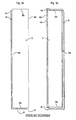
- a floorboard 1 of known design is illustrated from below and from above in Figs 3a and 3b, respectively.
- the board is rectangular with a top side 2, an underside 3, two opposite long sides 4a, 4b which form joint edges, and two opposite short sides 5a, 5b which form joint edges.
- the board 1 has a planar strip 6 which is mounted at the factory and which extends along one long side 4a, said strip extending along the entire long side 4a and being made of a flexible, resilient aluminium sheet.
- the strip 6 can be mechanically fixed according to the embodiment illustrated, or fixed by means of glue or in some other fashion.
- Other strip materials can be used, such as sheet of some other metal, and aluminium or plastic sections.
- the strip 6 can be integrally formed with the board 1, for example by some suitable working of the body of the board 1. However the strip 6 is always integrated with the board 1, i.e.
- the width of the strip 6 can be about 30 mm and its thickness about 0.5 mm.
- a similar, although shorter strip 6' is arranged also along one short side 5a of the board 1.
- the edge side of the strip 4 facing away from the joint edge 4a is formed with a locking element 8 extending along the entire strip 6.
- the locking element 8 has an active locking surface 10 facing the joint edge 4a and having a height of, for instance, 0.5 mm.
- the locking element 8 cooperates with a locking groove 14, which is formed in the underside 3 of the opposite long side 4b of an adjacent board 1'.
- the short side strip 6' is provided with a corresponding locking element 8' and the opposite short side 5b has a corresponding locking groove 14'.
- the board 1 is also formed, along one long side 4a and one short side 5a, with a laterally open recess 16.
- the recess 16 is defined downwards by the associated strips 6, 6'.
- Figs 1a-1c show how two such boards 1, 1' can be joined by downwards angling.
- Figs 2a-2c show how the boards 1, 1' can instead be joined by snap action.
- the long sides 4a, 4b can be joined by both methods, whereas the short sides 5a, 5b - after laying of the first row - are normally joined after joining of the long sides, and merely by snap action.
- the long side 4b of the new board 1' is pressed against the long side 4a of the previously laid board 1 according to Fig. 1a, so that the locking tongue 20 is inserted into the recess 16.
- the board 1' is then angled downwards to the subfloor 12 according to Fig. 1b. Now the locking tongue 20 completely enters the recess 16 while at the same time the locking element 8 of the strip 6 enters the locking groove 14. During this downwards angling, the upper part of the locking element 8 can be active and accomplish a guiding of the new board 1' towards the previously laid board 1.
- the boards 1, 1' are locked in both D1 direction and D2 direction, but can be displaced relative to each other in the longitudinal direction of the joint.
- Figs 2a-2c illustrate how also the short sides 5a and 5b of the boards 1, 1' can be mechanically joined in both D1 and D2 direction by the new board 1' being moved essentially horizontally towards the previously laid board 1. This can be carried out after the long side 4b of the new board 1' has been joined as described above.
- bevelled surfaces adjacent to the recess 16 and the locking tongue 20 cooperate so that the strip 6' is forced downwards as a direct consequence of the joining of the short sides 5a, 5b.
- the strip 6' snaps upwards as the locking element 8' enters the locking groove 14'.
- Norske Skog Flooring AS (licensee of Välinge Aluminium AB) introduced a laminate flooring with a mechanical joining system according to WO 94/26999 in January 1996 in connection with the Domotex fair in Hannover, Germany.
- This laminate flooring marketed under the trademark Alloc® is 7.6 mm thick, has a 0.6 mm aluminium strip 6 which is mechanically fixed on the tongue side and the active locking surface 10 of the locking element 8 has an inclination of about 80° to the plane of the board.
- the vertical joint is formed as a modified tongue-and-groove joint, where the term "modified" relates to the possibility of joining groove and tongue by inwards angling.
- WO 97/47834 discloses a mechanical joining system which is essentially based on the above prior-art principles. In the corresponding product which this applicant has begun to market in the latter part of 1997, biasing between the boards is strived for. This leads to high friction and difficulties in angling together and displacing the boards.
- the document shows a plurality of embodiments of the locking system.
- the general problem and the object of the invention thus are to provide a mechanical locking system of the type described above, which permits inwards angling from above, which counteracts backwards angling and which yields an exact fit between tongue and groove, while at the same time the manufacture can be optimised in respect of accuracy, number of critical parameters and costs of material.
- An object of the invention is to satisfy this demand.
- the invention is based on the understanding that with prior-art locking systems it is difficult to solve all the above problems and desiderata at the same time, which means that a modification of the locking systems is necessary.
- the invention is specifically based on the understanding that essentially all the above-mentioned requirements, problems and desiderata can be satisfied if the known tongue-and-groove joint is modified in a special manner.
- mechanical locking systems one has traditionally started from the design of the glued tongue-and-groove joint. From this starting point, the known vertical joint has then been supplemented with a horizontal lock and the tongue-and-groove joint has been modified so that inwards angling can more easily be carried out from above.
- a locking system for mechanical joining of floorboards, said locking system comprising a tongue-and-groove joint, the groove and tongue of which have cooperating upper abutment surfaces and cooperating lower abutment surfaces for vertical locking of two joint edges of two adjacent floorboards, said upper and lower abutment surfaces being essentially parallel with the principal plane of the floorboards, and said locking system comprising, for horizontal mechanical joining of the joint edges perpendicular to the same, a locking groove formed in the underside of a first one of the joint edges and extended in parallel therewith, and a portion projecting from the second joint edge and integrated with a body of the floorboard, said portion supporting, at a distance from the joint edge, a locking element cooperating with the locking groove, wherein said tongue is anglable into the groove, and wherein said locking element is insertable into the locking groove by a mutual angular motion of the boards about the joint edges.
- the locking system according to the invention is characterised in that, in the joined state, the cooperating upper abutment surfaces are limited horizontally inwards from the joint edge and horizontally outwards to the joint edge by an inner vertical plane and an outer vertical plane, respectively; that the tongue-and-groove joint is so designed that there is in the groove, in the joined state, between the inner vertical plane and the outer vertical plane and below the tongue, a space which extends horizontally from the inner vertical plane and at least halfway to the outer vertical plane; that the tongue-and-groove joint is further so designed that the boards, during a final phase of the inwards angling when the locking element is inserted into the locking groove, can take a position where there is a space in the groove between the inner and the outer vertical plane and below the tongue; and that the lower abutment surfaces are positioned essentially outside the outer vertical plane.
- cooperating abutment surfaces surfaces of tongue and groove which in the joined state of the floorboards either engage each other directly in the vertical direction or at least are in such immediate vicinity of each other in the vertical direction that they can be made to contact each other to prevent the boards from being relatively offset in the vertical direction.
- both upper and lower abutment surfaces are, as a rule, located in the inner part of the groove.
- planar abutment surfaces in the inner part of the groove, it is not possible to achieve a good fit as well as optimal inwards angling. If tongue and groove are equilaterally designed on the upper and lower side, the floorboards are just as easy to angle upwards as downwards/backwards.
- a locking system according to the invention can exhibit, both during the final inwards angling and in the joined state, a space in the groove under the tongue. Thanks to this space, the tongue can unimpededly be angled into the groove when two boards are joined by being angled together. Moreover, the locking system can be so designed that the angling together can take place while the boards are held in mutual contact at the upper corner portions of the adjacent joint edges. Despite the provision of this space in the groove under the tongue, it is according to the invention possible to achieve an exact vertical fit between tongue and groove in the joined state thanks to the fact that the lower abutment surfaces are, at least in large part, horizontally displaced outside the upper abutment surfaces.
- the present invention solves, at the same time, the problem of undesirable backwards angling of the boards thanks to the lower abutment surfaces being displaced relative to the upper abutment surfaces in the direction of the locking element.
- said displacement accomplishes an angular limitation of the movement of the tongue that effectively counteracts any angling of the tongue past its intended position in the groove, i.e. that counteracts backwards angling of the boards.
- the invention also presents the advantage that manufacture can be carried out with working tools which operate only in the plane of the floorboards, thanks to the fact that no curved surfaces are necessary in the tongue-and-groove joint.
- the tolerances of the vertical fit can thus be made considerably better.
- the space in the groove under the tongue thus solves not only a problem relating to inwards angling, but also solves the problem of achieving an exact vertical fit between the boards.
- the space has a function both during the inwards angling and in the joined state.
- the present invention provides a locking system for mechanical joining, which permits inwards angling from above, counteracts backwards angling and yields an exact fit between tongue and groove.
- Inwards angling can be carried out without any vertical play between tongue and groove and without necessitating opening of the groove when the tongue is pressed in.
- the depth of the tongue and groove does not affect the possibility of inwards angling and the fit between tongue and groove or the relative position of the floorboards.
- Backwards angling is counteracted, and the groove can be manufactured rationally by means of horizontally operating tools which also permit manufacture of the locking device in a machined wood fibre strip.
- the space in the groove under the tongue, in the joined state is horizontally extended essentially all the way from the outer vertical plane to the inner vertical plane.
- there is in the joined state a space over essentially the entire horizontal range in the groove, within which the cooperating upper abutment surfaces are extended.
- essentially no part of the lower abutment surfaces are positioned inside the outer vertical plane.
- this embodiment would be the most ideal one since the vertical fit between tongue and groove can then be optimised while at the same time the tongue can unimpededly be inserted into the groove.
- the space under the tongue can be limited downwards by a planar, horizontal surface of the groove, whose extension to the edge joint forms the lower abutment surface of the groove, or by a groove surface which is inclined to the horizontal plane or arcuate, or a combination of a planar surface and an inclined/arcuate surface of the groove.
- the space in the groove under the tongue can be formed by the tongue being bevelled/cut away, or by the groove being hollowed out.
- the groove has in the joined state an upper and a lower horizontal surface, which constitute inwardly directed extensions of the upper abutment surface and the lower abutment surface, respectively, of the groove, and there is also an inner horizontal play between the bottom of the groove and the tip of the tongue.
- the projecting portion is integrated with a body of the board.
- integrated should be considered to comprise (i) cases where the projecting portion is made of a separate component integrally connected with the body at the factory, (ii) cases where the projecting portion is formed in one piece with the body, and (iii) a combination of (i) and (ii), i.e. cases where the inner part of the projecting portion is formed in one piece with the body and its outer part consists of a separate factory-mounted component.
- a floorboard having a locking system according to the invention, on at least two opposite sides and preferably on all four sides to permit joining of all sides of the floorboards.
- Figs 1a-c show in three steps a downwards angling method for mechanical joining of long sides of floorboards according to WO 94/026999.
- Figs 2a-c show in three steps a snap-in method for mechanical joining of short sides of floorboards according to WO 94/26999.
- Figs 3a and 3b illustrate a floorboard according to WO 94/26999 seen from above and from below, respectively.
- Fig. 4 shows a floorboard with a locking system according to a first embodiment of the invention, an adjacent floorboard being broken away.
- Fig. 5 is a top plan view of a floorboard according to Fig. 4.
- Fig. 6a shows on a larger scale a broken-away corner portion C1 of the board in Fig. 5, and Figs 6b and 6c illustrate vertical sections of the joint edges along the long side 4a and the short side 5a of the board in Fig. 5, from which it specifically appears that the long side and the short side are different.
- Figs 7a-c illustrate a downwards angling method for mechanical joining of long sides of the floorboard according to Figs 4-6.
- Figs 8a-c illustrate a snap-in method for mechanical joining of short sides of the floorboard according to Figs 4-6.
- Fig. 9 illustrates a floorboard with a locking system according to a second embodiment of the invention.
- Figs 10a and 10b illustrate on a larger scale broken away details corresponding to Fig. 9 and the importance of a space in the inner part of the groove during inwards angling and in the joined state, respectively.
- Fig. 11 illustrates the making of the groove in the floorboard in Fig. 9.
- Fig. 4 is a sectional view of a long side 4a of the board 1, and also part of a long side 4b of an adjacent board 1.
- the body of the board 1 consists of a core 30 of, for instance, wood fibre, which supports a top laminate 32 on its front side and a balance layer 34 on its rear side.
- the board body 30-34 is rectangular with long sides 4a, 4b and short sides 5a, 5b.
- a separate strip 6 with a formed locking element 8 is mounted at the factory on the body 30-34, so that the strip 6 constitutes an integrated part of the completed floorboard 1.
- the strip 6 is made of resilient aluminium sheet.
- the aluminium sheet can have a thickness in the order of 0.6 mm and the floorboard a thickness in the order of 7 mm.
- the strip 6 For additional description of dimensions, possible materials, etc. for the strip 6, reference is made to the above description of the prior-art board.
- the strip 6 is formed with a locking element 8, whose active locking surface 10 cooperates with a locking groove 14 in the opposite joint edge 4b of the adjacent board 1' for horizontal interlocking of the boards 1, 1' transversely of the joint edge (D2).
- the joint edge 4a has a laterally open groove 36 and the opposite joint edge 4b has a laterally projecting tongue 38 (corresponding to the locking tongue 20), which in the joined state is received in the groove 36.
- the free surface of the upper part 40 of the groove 36 has a vertical upper portion 41, a bevelled portion 42 and an upper planar, horizontal abutment surface 43 for the tongue 38.
- the free surface of the lower part 44 of the groove 36 has a lower inclined surface 45', a lower planar, horizontal abutment surface 45 for the tongue 38, a bevelled portion 46 and a lower vertical portion 47.
- the opposite joint edge 4b (see Fig.
- the tongue 38 has an upper planar, horizontal abutment surface 49, an upper bevelled portion 50, a lower bevelled portion 51 and a lower planar, horizontal abutment surface 52.
- the boards 1, 1' are locked relative to each other in the vertical direction D1.
- An upwards movement of the board 1' is counteracted by engagement between the upper abutment surfaces 43 and 49 while a downwards movement of the board 1' is counteracted on the one hand by engagement between the lower abutment surfaces 45 and 52 and, on the other hand, by the board 1' resting on a lower surface portion 7 of the strip 6.
- the two juxtaposed upper portions 41 and 48 define a vertical joint plane F.
- an inner vertical plane IP and an outer vertical plane OP are indicated.
- the inner vertical plane IP is defined by the inner boundary line of the upper abutment surfaces 43, 49 while the outer vertical plane OP is defined by the outer boundary line of the upper abutment surfaces 43, 49.
- the lower part 44 of the groove 36 is extended a distance outside the joint plane F.
- the lower planar, horizontal abutment surface 45 of the groove 36 thus is positioned partially inside and partially outside the joint plane F while the upper abutment surface 43 of the groove 36 is positioned completely inside and at a distance from the joint plane F. More specifically, the upper abutment surface 43 of the groove 36 is in its entirety positioned between the vertical planes IP and OP while the lower abutment surface 45 of the groove 36 is in its entirety positioned outside the vertical plane OP and extends partially outside the joint plane F.
- the joint edge 4a is in its underside formed with a continuous mounting groove 54 having a vertical lower gripping edge 56 and an inclined gripping edge 58.
- the gripping edges formed of the surfaces 46, 47, 56, 58 together define a fixing shoulder 60 for mechanical fixing of the strip 6.
- the fixing is carried out according to the same principle as in the prior-art board and can be carried out with the methods described in the above documents.
- a continuous lip 62 of the strip 6 is thus bent round the gripping edges 56, 58 of the groove 54 while a plurality of punched tongues 64 are bent round the surfaces 46, 47 of the projecting portion 44.
- the tongues 64 and the associated punched holes 65 are shown in the broken-away view in Fig. 6a.
- Figs 7a-c The angling together of the long sides 4a, 4b can be carried out according to the same principle as in Figs 1a-c.
- a small downwards bending of the strip 6 can generally be carried out - not only for this embodiment - as shown in the laying sequence in Figs 7a-c.
- This downwards bending of the strip 6 together with an inclination of the locking element 8 makes it possible for the boards 1, 1' to be angled downwards and upwards again with very tight joint edges at the upper surfaces 41 and 48.
- the locking element 8 should preferably have a high guiding capability so that the boards in connection with downwards angling are pushed towards the joint edge.
- the locking element 8 should have a large guiding part.
- the boards after being joined and along their long sides 4a, 4b, should be able to take a position where there is a small play between locking element and locking groove, which need not be greater than 0.02-0.05 mm. This play permits displacement and bridges width tolerances. The friction in the joint should be low.
- Figs 8a-c illustrate that snapping together of the short sides 5a, 5b can be carried out according to the same principle as in Figs 2a-c.
- the locking system on the short sides in this embodiment is designed differently from the long sides and is specifically adapted for snapping in by vertical displacement and downwards bending of the strip.
- the projecting portion P - here in the form of an aluminium strip 6' - on the short sides 5a, 5b is arranged on the same joint edge 5a as the tongue 38' while the locking groove 14' is formed in the same joint edge 5b as the groove 36.
- the locking element 8' on the short sides is somewhat lower than the locking element 8 on the long sides.
- Figs 8a-c in fact has double tongue-and-groove joints, one tongue and one groove on each joint edge, both joints being designed according to the invention with displaced upper and lower abutment surfaces.
- Fig. 9 shows a second embodiment of a locking system according to the invention.
- the projecting portion P is formed, by machining, in one piece with the body of the board 1.
- the body can be composed of the same materials as in the previous embodiment.
- the vertical planes IP, OP and F are also indicated according to the previous definition.
- the lower abutment surfaces 45, 52 are entirely displaced outside the outer vertical plane OP.
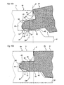
- Fig. 10a shows on a larger scale how a downwards angling of the tongue 38 in the embodiment in Fig. 9 has already begun.
- the tongue 38 is in its lower part defined by a planar abutment surface 52 and a bevelled portion 51.
- the groove 36 in Fig. 9, however, is fully planar at the bottom, i.e. the planar, horizontal surface 45 extends all the way to the bottom of the groove 36.
- Reference numerals 52' and 51' indicate boundary lines of a prior-art tongue.
- it would with such a known design not be possible to easily angle the tongue 38 inwards into the groove 36 since the corner portion 53 of the tongue 38 would strike against the surface 45 of the groove 36.
- Such a tongue would therefore have to be pressed into the groove if at all possible.
- Fig. 10b shows the embodiment in Fig. 9 in the joined state.
- IP and OP there is under the tongue 38 still a space S, which also extends all the way between IP and OP.
- FIG. 11 schematically shows the making of the groove 35 in the embodiment in Fig. 9.
- a rotating working tool 80 with a cutting element 81 of, for instance, hard metal or diamond rotates about an axis A at a distance from the locking element 8.
- Such horizontal working by means of a tool with a relatively large diameter is possible thanks to the locking element 8 being positioned on the same level or on a level under the lower abutment surface 45 of the groove 36.
- the major part of the short sides is locked by snap action, as described above with reference to Figs 8a-c.
- the first row is frequently laid by angling together the short sides, in the same manner as described for the long sides in connection with Figs 7a-c.
- the short sides can both be pulled apart along the joint and be angled upwards. As a rule, upwards angling is a quicker operation.
- the inventive locking system should thus be designed while also taking into consideration the possibility of angling the short side.
- the aspects of the invention which include a separate strip can preferably be implemented in combination with use of an equalising groove of the kind described in WO 94/26999.
- Adjacent joint edges are equalised in the thickness direction by working of the underside, so that the upper sides of the floorboards are aligned with each other when the boards have been joined.
- Reference E in Fig. 1a indicates that the body of the boards after such working has the same thickness in adjacent joint edges.
- the strip 6 is received in the groove and will thus be partly flush-mounted in the underside of the floor.
- a corresponding arrangement can thus be realised also in combination with the invention as shown in the drawings.
Landscapes
- Engineering & Computer Science (AREA)
- Architecture (AREA)
- Civil Engineering (AREA)
- Structural Engineering (AREA)
- Wood Science & Technology (AREA)
- Life Sciences & Earth Sciences (AREA)
- Physics & Mathematics (AREA)
- Electromagnetism (AREA)
- Floor Finish (AREA)
- Connection Of Plates (AREA)
- Vehicle Step Arrangements And Article Storage (AREA)
- Body Structure For Vehicles (AREA)
- Structure Of Telephone Exchanges (AREA)
- Joining Of Building Structures In Genera (AREA)
- Slide Fasteners (AREA)
- Handcart (AREA)
Abstract
Description
that, in the joined state, the cooperating upper abutment surfaces are limited horizontally inwards from the joint edge and horizontally outwards to the joint edge by an inner vertical plane and an outer vertical plane, respectively;
that the tongue-and-groove joint is so designed that there is in the groove, in the joined state, between the inner vertical plane and the outer vertical plane and below the tongue, a space which extends horizontally from the inner vertical plane and at least halfway to the outer vertical plane;
that the tongue-and-groove joint is further so designed that the boards, during a final phase of the inwards angling when the locking element is inserted into the locking groove, can take a position where there is a space in the groove between the inner and the outer vertical plane and below the tongue; and
that the lower abutment surfaces are positioned essentially outside the outer vertical plane.
Claims (19)
- A locking system for mechanical joining of floorboards (1), said locking system comprising a tongue-and-groove joint (36, 38), the groove (36) and tongue (38) of which have cooperating upper abutment surfaces (43, 49) and cooperating lower abutment surfaces (45, 52) for vertical locking of two joint edges (4a, 4b) of two adjacent floorboards (1, 1'), said upper and lower abutment surfaces (43, 49; 45, 52) being essentially parallel with the principal plane of the floorboards (1), and said locking system comprising, for horizontal mechanical joining of the joint edges (4a, 4b) perpendicular to the same, a locking groove (14) formed in the underside (3) of a first one of the joint edges (4b) and extended in parallel therewith, and a portion (P) projecting from the second joint edge (4a) and integrated with a body (30, 32, 34) of the floorboard (1), said portion (P) supporting, at a distance from the joint edge (4a), a locking element (8) cooperating with the locking groove (14), wherein said tongue (38) is anglable into the groove (36), and wherein the locking element (8) is insertable into the locking groove (14) by mutual angular motion of the boards (1, 1') about upper portions (41, 48) of the joint edges (4a, 4b), characterised in that, in the joined state, the cooperating upper abutment surfaces (43, 49) are limited horizontally inwards from the joint edge and horizontally outwards to the joint edge by an inner vertical plane (IP) and an outer vertical plane (OP), respectively;
that the tongue-and-groove joint is so designed that there is in the groove (45), in the joined state, between the inner vertical plane (IP) and the outer vertical plane (OP) and below the tongue (38), a space (S) which extends horizontally from the inner vertical plane (IP) and at least halfway to the outer vertical plane (OP);
that the tongue-and-groove joint is further so designed that the boards, during a final phase of the inwards angling when the locking element is inserted into the locking groove, can take a position where there is a space (S) in the groove (36) between the inner and the outer vertical plane (IP, OP) and below the tongue (38) ; and
that the lower abutment surfaces (45, 52) are positioned essentially outside the outer vertical plane (OP). - A locking system as claimed in claim 1, wherein said space (S) in the joined state is horizontally extended below the tongue (38) essentially all the way from the inner vertical plane (IP) to the outer vertical plane (OP), so that essentially no part of the lower abutment surfaces (45, 52) is positioned inside the outer vertical plane (OP).
- A locking system as claimed in claim 1 or 2, wherein said space (S) during the final phase of the inwards angling is horizontally extended below the tongue (38) essentially all the way from the inner vertical plane (IP) to the outer vertical plane (OP).
- A locking system as claimed in any one of the preceding claims, wherein the groove (36) in the joined state has an upper and a lower horizontal surface which constitute inwardly directed extensions of the upper abutment surface (43) and the lower abutment surface (45), respectively, of the groove (36), and wherein there is in the joined state a horizontal play (Δ) between the bottom of the groove (36) and the tip of the tongue (38).
- A locking system as claimed in any one of the preceding claims, wherein the outer vertical plane (OP) is located at a horizontal distance inside a vertical joint plane (F), which is defined by adjoining upper portions (41, 48) of the joined joint edges (4a, 4b) of the two boards (1, 1').
- A locking system as claimed in any one of the preceding claims, wherein the lower abutment surfaces (45, 52) are located at least partially outside a vertical joint plane (F) which is defined by adjoining upper portions (41, 48) of the joined joint edges (4a, 4b) of the two boards (1, 1').
- A locking system as claimed in claim 6, wherein the major part of the lower abutment surfaces (45, 52) is positioned outside the vertical joint plane (F).
- A locking system as claimed in any one of the preceding claims, wherein the projecting portion (P) and the groove (36) are arranged in one and the same joint edge (4a) of the floorboard (1).
- A locking system as claimed in any one of the preceding claims, wherein the projecting portion (P) is at least partially made in one piece with a body (30, 32, 34) of the floorboard (1).
- A locking system as claimed in claim 9, wherein the locking element (8) of the projection portion (P) is positioned under or on a level with the lower abutment surface (45) of the groove (36).
- A locking system as claimed in any one of the preceding claims, wherein the projecting portion (P) is at least partially formed of a material other than that of the body of the floorboard.
- A locking system as claimed in claim 11, wherein the projecting portion (P) is at least partially formed of a separate strip (6) which is integrally connected (60, 62, 64) with the board (1) by being mounted in the factory.
- A locking system as claimed in any one of the preceding claims, wherein the projecting portion (P) is resilient transversely of the principal plane of the floorboards.
- A locking system as claimed in any one of the preceding claims, wherein the tongue (38) is insertable into the groove (36) and the locking element (8) is insertable into the locking groove (14) by a mutual horizontal joining of the joint edges (5a, 5b) of the boards.
- A locking system as claimed in claim 14, wherein the groove (36) has in its upper part a bevelled portion (42) for guiding the tongue (38) into the groove (36).
- A locking system as claimed in any one of the preceding claims, wherein the projecting portion (P), in the horizontal direction between the lower abutment surfaces (45, 52) of the tongue-and-groove joint on the one hand and the locking element (8) of the projecting portion (P) on the other hand, has a lower portion (7) which is positioned below said lower abutment surfaces (45, 52).
- A locking system as claimed in any one of the preceding claims, wherein the tongue (38) is anglable into the groove (36) and the locking element (8) is insertable into the locking groove (14) by said mutual angular motion of the boards about upper portions (41, 48) of the joint edges (4a, 4b) while said upper portions (41, 48) are-held in mutual contact.
- A floorboard (1) provided along one or more sides with a locking system as claimed in any one of the preceding claims.
- A floorboard (1) as claimed in claim 18, which has opposite long sides and short sides and which is mechanically joinable along its long sides with long sides of identical floorboards by downward angling and which is mechanically joinable along its short sides with short sides of identical floorboards by displacement along said long sides.
Priority Applications (3)
| Application Number | Priority Date | Filing Date | Title |
|---|---|---|---|
| DE29924537U DE29924537U1 (en) | 1998-06-03 | 1999-05-31 | Locking system for mechanical joining of floor boards |
| DE29924535U DE29924535U1 (en) | 1998-06-03 | 1999-05-31 | Locking system for mechanical joining of floor boards |
| DE29924536U DE29924536U1 (en) | 1998-06-03 | 1999-05-31 | Locking system for mechanical joining of floor boards |
Applications Claiming Priority (3)
| Application Number | Priority Date | Filing Date | Title |
|---|---|---|---|
| SE9801987 | 1998-06-03 | ||
| SE9801987A SE512290C2 (en) | 1998-06-03 | 1998-06-03 | Locking system for mechanical joining of floorboards and floorboard provided with the locking system |
| PCT/SE1999/000933 WO1999066151A1 (en) | 1998-06-03 | 1999-05-31 | Locking system and flooring board |
Publications (3)
| Publication Number | Publication Date |
|---|---|
| EP1084317A1 EP1084317A1 (en) | 2001-03-21 |
| EP1084317B1 true EP1084317B1 (en) | 2003-04-23 |
| EP1084317B2 EP1084317B2 (en) | 2008-09-17 |
Family
ID=20411583
Family Applications (1)
| Application Number | Title | Priority Date | Filing Date |
|---|---|---|---|
| EP99930052A Expired - Lifetime EP1084317B2 (en) | 1998-06-03 | 1999-05-31 | Locking system and flooring board |
Country Status (14)
| Country | Link |
|---|---|
| US (6) | US7444791B1 (en) |
| EP (1) | EP1084317B2 (en) |
| JP (1) | JP3515075B2 (en) |
| CN (1) | CN1304475A (en) |
| AT (1) | ATE238469T1 (en) |
| AU (1) | AU735245B2 (en) |
| BR (1) | BR9911186A (en) |
| CA (1) | CA2333962A1 (en) |
| DE (1) | DE69907179C5 (en) |
| ES (1) | ES2193721T5 (en) |
| NO (1) | NO314909B1 (en) |
| PT (1) | PT1084317E (en) |
| SE (1) | SE512290C2 (en) |
| WO (1) | WO1999066151A1 (en) |
Cited By (8)
| Publication number | Priority date | Publication date | Assignee | Title |
|---|---|---|---|---|
| EP3686029A1 (en) | 2019-01-23 | 2020-07-29 | Flooring Technologies Ltd. | Method for producing an abrasion-resistant and waterproof multilayer panel and a panel obtained with said method |
| EP3686008A1 (en) | 2019-01-23 | 2020-07-29 | Flooring Technologies Ltd. | Method for producing an abrasion-resistant and waterproof multilayer panel and a panel obtained with said method |
| WO2020178037A1 (en) | 2019-03-01 | 2020-09-10 | Flooring Technologies Ltd. | Method for producing a multilayer, surface-structured panel, and a panel produced by this method |
| EP3851294A1 (en) | 2020-01-15 | 2021-07-21 | Flooring Technologies Ltd. | Method and device for providing laminate panels with individualized decorative elements |
| WO2021144201A1 (en) | 2020-01-13 | 2021-07-22 | Flooring Technologies Ltd. | Method and device for providing laminate panels provided with individualised decorations |
| US11872837B2 (en) | 2019-01-22 | 2024-01-16 | Flooring Technologies Ltd. | Abrasion-resistant wood board |
| US11884097B2 (en) | 2016-05-20 | 2024-01-30 | Flooring Technologies Ltd. | Method for producing an abrasion-resistant wood material panel and production line therefor |
| US11976470B2 (en) | 2019-03-12 | 2024-05-07 | Flooring Technologies Ltd. | Hard floor panel for floating installation with the formation of a flooring panel network |
Families Citing this family (170)
| Publication number | Priority date | Publication date | Assignee | Title |
|---|---|---|---|---|
| SE515210C2 (en) | 2000-04-10 | 2001-06-25 | Valinge Aluminium Ab | Locking systems for joining floorboards and floorboards provided with such locking systems and floors formed from such floorboards |
| US7086205B2 (en) | 1993-05-10 | 2006-08-08 | Valinge Aluminium Ab | System for joining building panels |
| SE501014C2 (en) * | 1993-05-10 | 1994-10-17 | Tony Pervan | Grout for thin liquid hard floors |
| US6588166B2 (en) | 1995-03-07 | 2003-07-08 | Pergo (Europe) Ab | Flooring panel or wall panel and use thereof |
| SE9500810D0 (en) | 1995-03-07 | 1995-03-07 | Perstorp Flooring Ab | Floor tile |
| US6421970B1 (en) | 1995-03-07 | 2002-07-23 | Perstorp Flooring Ab | Flooring panel or wall panel and use thereof |
| US7131242B2 (en) | 1995-03-07 | 2006-11-07 | Pergo (Europe) Ab | Flooring panel or wall panel and use thereof |
| US7992358B2 (en) | 1998-02-04 | 2011-08-09 | Pergo AG | Guiding means at a joint |
| US7386963B2 (en) * | 1998-06-03 | 2008-06-17 | Valinge Innovation Ab | Locking system and flooring board |
| SE512313E (en) | 1998-06-03 | 2004-03-16 | Valinge Aluminium Ab | Locking system and floorboard |
| SE512290C2 (en) * | 1998-06-03 | 2000-02-28 | Valinge Aluminium Ab | Locking system for mechanical joining of floorboards and floorboard provided with the locking system |
| SE514645C2 (en) | 1998-10-06 | 2001-03-26 | Perstorp Flooring Ab | Floor covering material comprising disc-shaped floor elements intended to be joined by separate joint profiles |
| SE515789C2 (en) | 1999-02-10 | 2001-10-08 | Perstorp Flooring Ab | Floor covering material comprising floor elements which are intended to be joined vertically |
| SE517478C2 (en) | 1999-04-30 | 2002-06-11 | Valinge Aluminium Ab | Locking system for mechanical hoisting of floorboards, floorboard provided with the locking system and method for producing mechanically foldable floorboards |
| DE29911462U1 (en) * | 1999-07-02 | 1999-11-18 | Akzenta Paneele & Profile Gmbh | Fastening system for panels |
| US7877956B2 (en) | 1999-07-05 | 2011-02-01 | Pergo AG | Floor element with guiding means |
| US6863768B2 (en) | 1999-11-08 | 2005-03-08 | Premark Rwp Holdings Inc. | Water resistant edge of laminate flooring |
| US7763345B2 (en) | 1999-12-14 | 2010-07-27 | Mannington Mills, Inc. | Thermoplastic planks and methods for making the same |
| US7337588B1 (en) * | 1999-12-27 | 2008-03-04 | Maik Moebus | Panel with slip-on profile |
| SE517183C2 (en) * | 2000-01-24 | 2002-04-23 | Valinge Aluminium Ab | Locking system for mechanical joining of floorboards, floorboard provided with the locking system and method for making such floorboards |
| EP1120515A1 (en) * | 2000-01-27 | 2001-08-01 | Triax N.V. | A combined set comprising a locking member and at least two building panels |
| SE522860C2 (en) | 2000-03-10 | 2004-03-09 | Pergo Europ Ab | Vertically joined floor elements comprising a combination of different floor elements |
| EP2813636B1 (en) * | 2000-03-31 | 2017-12-27 | Pergo (Europe) AB | A flooring material of sheet-shaped floor elements joined with joining members. |
| SE518184C2 (en) | 2000-03-31 | 2002-09-03 | Perstorp Flooring Ab | Floor covering material comprising disc-shaped floor elements which are joined together by means of interconnecting means |
| FR2807694B1 (en) | 2000-04-14 | 2002-07-05 | Europ De Laquage Et De Faconna | DEVICE FOR ASSEMBLING LONGITUDINAL EDGES OF PANELS, SLATS OR PANELS |
| FR2808822B1 (en) | 2000-05-15 | 2003-01-03 | Europ De Laquage Et De Faconna | DEVICE FOR ASSEMBLING THE LONGITUDINAL EDGES OF PANELS, SLATS OR PANELS, WITH FORCE DISTRIBUTION |
| AT411374B (en) | 2000-06-06 | 2003-12-29 | Kaindl M | COATING, COVERING OR THE LIKE, PANELS FOR ITS EDUCATION AND METHOD AND DEVICE FOR PRODUCING THE PANELS |
| BE1013569A3 (en) | 2000-06-20 | 2002-04-02 | Unilin Beheer Bv | Floor covering. |
| US6803099B1 (en) | 2000-10-10 | 2004-10-12 | Armstrong World Industries, Inc. | Self-adhering surface covering and method of making |
| CA2434168C (en) | 2001-01-12 | 2009-10-27 | Vaelinge Aluminium Ab | Floorboards and methods for production and installation thereof |
| US6769218B2 (en) | 2001-01-12 | 2004-08-03 | Valinge Aluminium Ab | Floorboard and locking system therefor |
| US6851241B2 (en) | 2001-01-12 | 2005-02-08 | Valinge Aluminium Ab | Floorboards and methods for production and installation thereof |
| DE10103505B4 (en) | 2001-01-26 | 2008-06-26 | Pergo (Europe) Ab | Floor or wall panel |
| FR2825734B1 (en) | 2001-06-12 | 2004-07-09 | Europ De Laquage Et De Faconna | DEVICE FOR ASSEMBLING PANELS, SLATS OR PANELS, WITH FORCE DISTRIBUTION |
| SE519791C2 (en) | 2001-07-27 | 2003-04-08 | Valinge Aluminium Ab | System for forming a joint between two floorboards, floorboards therefore provided with sealing means at the joint edges and ways of manufacturing a core which is processed into floorboards |
| US8028486B2 (en) | 2001-07-27 | 2011-10-04 | Valinge Innovation Ab | Floor panel with sealing means |
| DE20122778U1 (en) * | 2001-08-10 | 2007-10-25 | Akzenta Paneele + Profile Gmbh | Panel and fastening system for panels |
| FR2828703A1 (en) | 2001-08-14 | 2003-02-21 | Europ De Laquage Et De Faconna | PROCESS FOR LAYING PANELS, SLATS OR SIDINGS INCLUDING A FORCE DISTRIBUTION EDGE ASSEMBLY DEVICE |
| SE525558C2 (en) | 2001-09-20 | 2005-03-08 | Vaelinge Innovation Ab | System for forming a floor covering, set of floorboards and method for manufacturing two different types of floorboards |
| US8250825B2 (en) | 2001-09-20 | 2012-08-28 | Välinge Innovation AB | Flooring and method for laying and manufacturing the same |
| SE525661C2 (en) | 2002-03-20 | 2005-03-29 | Vaelinge Innovation Ab | Floor boards decorative joint portion making system, has surface layer with underlying layer such that adjoining edge with surface has underlying layer parallel to horizontal plane |
| JP4472355B2 (en) | 2002-04-03 | 2010-06-02 | ベーリンゲ、イノベイション、アクチボラグ | Mechanical locking system for floorboard |
| SE525657C2 (en) | 2002-04-08 | 2005-03-29 | Vaelinge Innovation Ab | Flooring boards for floating floors made of at least two different layers of material and semi-finished products for the manufacture of floorboards |
| US8850769B2 (en) | 2002-04-15 | 2014-10-07 | Valinge Innovation Ab | Floorboards for floating floors |
| US7051486B2 (en) | 2002-04-15 | 2006-05-30 | Valinge Aluminium Ab | Mechanical locking system for floating floor |
| US7739849B2 (en) * | 2002-04-22 | 2010-06-22 | Valinge Innovation Ab | Floorboards, flooring systems and methods for manufacturing and installation thereof |
| US8375673B2 (en) | 2002-08-26 | 2013-02-19 | John M. Evjen | Method and apparatus for interconnecting paneling |
| US7617651B2 (en) | 2002-11-12 | 2009-11-17 | Kronotec Ag | Floor panel |
| DE10252866B3 (en) | 2002-11-12 | 2004-04-29 | Kronotec Ag | Panel used as a floor panel in laminate flooring comprises a support plate made of sized and compacted fiber material and having an upper side with a lower density than a lower side |
| DE10252863B4 (en) | 2002-11-12 | 2007-04-19 | Kronotec Ag | Wood fiber board, in particular floor panel |
| DE50309830D1 (en) | 2002-11-15 | 2008-06-26 | Flooring Technologies Ltd | Device consisting of two interconnected construction panels and an insert for locking these building panels |
| BE1015239A3 (en) * | 2002-12-09 | 2004-11-09 | Flooring Ind Ltd | Floor panel and method for linking, or removing from floor panels. |
| DE10306118A1 (en) | 2003-02-14 | 2004-09-09 | Kronotec Ag | building board |
| KR101206395B1 (en) | 2003-02-24 | 2012-11-29 | 뵈린게 이노베이션 에이비이 | Floorboard and method of manufacturing thereof |
| US20040206036A1 (en) | 2003-02-24 | 2004-10-21 | Valinge Aluminium Ab | Floorboard and method for manufacturing thereof |
| US7678425B2 (en) | 2003-03-06 | 2010-03-16 | Flooring Technologies Ltd. | Process for finishing a wooden board and wooden board produced by the process |
| US7845140B2 (en) | 2003-03-06 | 2010-12-07 | Valinge Innovation Ab | Flooring and method for installation and manufacturing thereof |
| US7677001B2 (en) | 2003-03-06 | 2010-03-16 | Valinge Innovation Ab | Flooring systems and methods for installation |
| DE20304761U1 (en) | 2003-03-24 | 2004-04-08 | Kronotec Ag | Device for connecting building boards, in particular floor panels |
| AT413840B (en) * | 2003-07-07 | 2006-06-15 | Poschacher Natursteinwerke Gmb | PLATE FOR LAYING ON FLOORS, WALLS, CEILINGS, FAÇADES OR DGL. |
| ATE394559T1 (en) * | 2003-09-05 | 2008-05-15 | Tilo Gmbh | ELEMENT FOR A FLOORING COVERING WITH A THIN MIDDLE LAYER |
| DE10362218B4 (en) | 2003-09-06 | 2010-09-16 | Kronotec Ag | Method for sealing a building board |
| DE20315676U1 (en) | 2003-10-11 | 2003-12-11 | Kronotec Ag | Panel, especially floor panel |
| US7886497B2 (en) | 2003-12-02 | 2011-02-15 | Valinge Innovation Ab | Floorboard, system and method for forming a flooring, and a flooring formed thereof |
| US7261947B2 (en) * | 2003-12-04 | 2007-08-28 | Awi Licensing Company | Plywood laminate having improved dimensional stability and resistance to warping and delamination |
| US7506481B2 (en) | 2003-12-17 | 2009-03-24 | Kronotec Ag | Building board for use in subfloors |
| USD528671S1 (en) | 2003-12-17 | 2006-09-19 | Kronotec Ag | Building board |
| US7516588B2 (en) | 2004-01-13 | 2009-04-14 | Valinge Aluminium Ab | Floor covering and locking systems |
| US20050166516A1 (en) | 2004-01-13 | 2005-08-04 | Valinge Aluminium Ab | Floor covering and locking systems |
| DE102004005047B3 (en) | 2004-01-30 | 2005-10-20 | Kronotec Ag | Method and device for introducing a strip forming the spring of a plate |
| DE102004011931B4 (en) | 2004-03-11 | 2006-09-14 | Kronotec Ag | Insulation board made of a wood-material-binder fiber mixture |
| BE1016216A5 (en) * | 2004-09-24 | 2006-05-02 | Flooring Ind Ltd | FLOOR PANEL AND FLOOR COVERING COMPOSED OF SUCH FLOOR PANELS. |
| SE527570C2 (en) | 2004-10-05 | 2006-04-11 | Vaelinge Innovation Ab | Device and method for surface treatment of sheet-shaped material and floor board |
| SI1650375T2 (en) | 2004-10-22 | 2011-04-29 | Vaelinge Innovation Ab | A set of floor panels |
| US7454875B2 (en) | 2004-10-22 | 2008-11-25 | Valinge Aluminium Ab | Mechanical locking system for floor panels |
| US7841144B2 (en) | 2005-03-30 | 2010-11-30 | Valinge Innovation Ab | Mechanical locking system for panels and method of installing same |
| US8215078B2 (en) | 2005-02-15 | 2012-07-10 | Välinge Innovation Belgium BVBA | Building panel with compressed edges and method of making same |
| BE1016938A6 (en) | 2005-03-31 | 2007-10-02 | Flooring Ind Ltd | Floor panel manufacturing method, involves providing panels at lower side with guiding groove and providing two opposite sides with profiled edge regions that comprise coupling parts |
| US20130139478A1 (en) | 2005-03-31 | 2013-06-06 | Flooring Industries Limited, Sarl | Methods for packaging floor panels, as well as packed set of floor panels |
| US8061104B2 (en) | 2005-05-20 | 2011-11-22 | Valinge Innovation Ab | Mechanical locking system for floor panels |
| US20060260253A1 (en) * | 2005-05-23 | 2006-11-23 | Quality Craft Ltd. | Laminate flooring panel bevel and method of manufacturing same |
| US8082717B2 (en) * | 2005-06-06 | 2011-12-27 | Dirk Dammers | Panel, in particular floor panel |
| SE529664C2 (en) | 2005-07-11 | 2007-10-16 | Pergo Europ Ab | A joint profile for a panel |
| SE529076C2 (en) | 2005-07-11 | 2007-04-24 | Pergo Europ Ab | A joint for panels |
| DE102005042657B4 (en) | 2005-09-08 | 2010-12-30 | Kronotec Ag | Building board and method of manufacture |
| DE102005042658B3 (en) | 2005-09-08 | 2007-03-01 | Kronotec Ag | Tongued and grooved board for flooring has at least one side surface and tongue and/or groove with decorative layer applied |
| US7854986B2 (en) | 2005-09-08 | 2010-12-21 | Flooring Technologies Ltd. | Building board and method for production |
| DE102005063034B4 (en) | 2005-12-29 | 2007-10-31 | Flooring Technologies Ltd. | Panel, in particular floor panel |
| SE530653C2 (en) | 2006-01-12 | 2008-07-29 | Vaelinge Innovation Ab | Moisture-proof floor board and floor with an elastic surface layer including a decorative groove |
| DE102006006124A1 (en) | 2006-02-10 | 2007-08-23 | Flooring Technologies Ltd. | Device for locking two building panels |
| DE102006007976B4 (en) | 2006-02-21 | 2007-11-08 | Flooring Technologies Ltd. | Process for refining a building board |
| DE102006008792A1 (en) | 2006-02-24 | 2007-08-30 | Isaria Corporate Design Ag | Structure plate for forming e.g. floor tile, has connection receiving unit provided for connecting unit, where longitudinal slot and unit are arranged on top of each other in two levels in vertically-shifted manner |
| BE1017157A3 (en) | 2006-06-02 | 2008-03-04 | Flooring Ind Ltd | FLOOR COVERING, FLOOR ELEMENT AND METHOD FOR MANUFACTURING FLOOR ELEMENTS. |
| SE533410C2 (en) | 2006-07-11 | 2010-09-14 | Vaelinge Innovation Ab | Floor panels with mechanical locking systems with a flexible and slidable tongue as well as heavy therefore |
| US7861482B2 (en) | 2006-07-14 | 2011-01-04 | Valinge Innovation Ab | Locking system comprising a combination lock for panels |
| US11725394B2 (en) | 2006-11-15 | 2023-08-15 | Välinge Innovation AB | Mechanical locking of floor panels with vertical folding |
| US8689512B2 (en) | 2006-11-15 | 2014-04-08 | Valinge Innovation Ab | Mechanical locking of floor panels with vertical folding |
| SE531111C2 (en) | 2006-12-08 | 2008-12-23 | Vaelinge Innovation Ab | Mechanical locking of floor panels |
| US8353140B2 (en) | 2007-11-07 | 2013-01-15 | Valinge Innovation Ab | Mechanical locking of floor panels with vertical snap folding |
| WO2009061279A1 (en) | 2007-11-07 | 2009-05-14 | Välinge Innovation AB | Mechanical locking of floor panels with vertical snap folding and an installation method to connect such panels |
| US7805903B2 (en) * | 2007-12-13 | 2010-10-05 | Liu David C | Locking mechanism for flooring boards |
| EP2235285B1 (en) | 2008-01-31 | 2019-06-26 | Välinge Innovation AB | Mechanical locking of floor panels |
| US8029880B2 (en) | 2008-04-24 | 2011-10-04 | Liu David C | Water resistant wide flooring boards |
| SG172871A1 (en) * | 2009-01-30 | 2011-08-29 | Vaelinge Innovation Belgium Bvba | Mechanical lockings of floor panels and a tongue blank |
| EP2401444B1 (en) * | 2009-02-27 | 2015-11-25 | AWI Licensing Company | Linear surface covering system |
| EP3750676B1 (en) | 2009-07-31 | 2023-04-26 | Välinge Innovation AB | Tool configuration relating to edge machining of building panels |
| CA2764964C (en) | 2009-07-31 | 2017-09-26 | Vaelinge Innovation Ab | Methods and arrangements relating to edge machining of building panels |
| US11717901B2 (en) | 2009-07-31 | 2023-08-08 | Valinge Innovation Ab | Methods and arrangements relating to edge machining of building panels |
| US11725395B2 (en) | 2009-09-04 | 2023-08-15 | Välinge Innovation AB | Resilient floor |
| EP2473687B1 (en) | 2009-09-04 | 2019-04-24 | Välinge Innovation AB | A method of assembling resilient floorboards which are provided with a mechanical locking system |
| US8365499B2 (en) | 2009-09-04 | 2013-02-05 | Valinge Innovation Ab | Resilient floor |
| CN102652201B (en) | 2009-12-17 | 2014-11-12 | 瓦林格创新股份有限公司 | Method and apparatus relating to surface shaping of building panels |
| EP4092213B1 (en) | 2010-01-11 | 2023-12-13 | Välinge Innovation AB | Floor covering with interlocking design |
| EP3702549B1 (en) | 2010-01-12 | 2023-05-10 | Välinge Innovation AB | Set of floor panels |
| DE102010004717A1 (en) | 2010-01-15 | 2011-07-21 | Pergo (Europe) Ab | Set of panels comprising retaining profiles with a separate clip and method for introducing the clip |
| BR112012018285B1 (en) | 2010-02-04 | 2020-02-18 | Välinge Innovation AB | SET OF FLOOR PANELS |
| WO2011109695A1 (en) * | 2010-03-05 | 2011-09-09 | Texas Heart Institute | Ets2 and mesp1 generate cardiac progenitors from fibroblasts |
| CN104831904B (en) | 2010-05-10 | 2017-05-24 | 佩尔戈(欧洲)股份公司 | Set of panels |
| CN102261178A (en) * | 2010-05-25 | 2011-11-30 | 康为敦 | Lock catch floor jointing structure |
| EP2657428B1 (en) * | 2010-10-20 | 2018-08-08 | Kronoplus Technical AG | Surface covering comprising laminate panels and an extraneous locking element |
| US8191328B1 (en) * | 2011-02-04 | 2012-06-05 | Liu David C | Hardwood flooring with sliding locking mechanism |
| US8806832B2 (en) | 2011-03-18 | 2014-08-19 | Inotec Global Limited | Vertical joint system and associated surface covering system |
| UA114715C2 (en) | 2011-07-05 | 2017-07-25 | Сералок Інновейшн Аб | Mechanical locking of floor panels with a glued tongue |
| US9725912B2 (en) | 2011-07-11 | 2017-08-08 | Ceraloc Innovation Ab | Mechanical locking system for floor panels |
| US8650826B2 (en) | 2011-07-19 | 2014-02-18 | Valinge Flooring Technology Ab | Mechanical locking system for floor panels |
| US8857126B2 (en) | 2011-08-15 | 2014-10-14 | Valinge Flooring Technology Ab | Mechanical locking system for floor panels |
| US8763340B2 (en) | 2011-08-15 | 2014-07-01 | Valinge Flooring Technology Ab | Mechanical locking system for floor panels |
| PT3115161T (en) | 2011-08-29 | 2020-02-06 | Ceraloc Innovation Ab | Mechanical locking system for floor panels |
| BE1020433A3 (en) * | 2012-01-05 | 2013-10-01 | Flooring Ind Ltd Sarl | PANEL. |
| CN104302854B (en) | 2012-05-08 | 2017-01-18 | 古斯塔夫康氏公司 | Core, panel blank, floor panel and method for its production |
| EP2662192B1 (en) | 2012-05-08 | 2017-07-12 | Ab Gustaf Kähr | Floor panel and method of its production |
| US20170204620A9 (en) | 2012-05-10 | 2017-07-20 | Michael Freedman & Associates, Inc. | Multi-layer acoustical flooring tile and method of manufacture |
| RS60954B1 (en) | 2012-06-19 | 2020-11-30 | Vaelinge Innovation Ab | Mechanical locking system for floorboards |
| US9140010B2 (en) | 2012-07-02 | 2015-09-22 | Valinge Flooring Technology Ab | Panel forming |
| KR102238758B1 (en) | 2012-07-02 | 2021-04-08 | 세라록 이노베이션 에이비 | A building panels, a method to produce of floor panels and a wooden based floor panel, with reduced weight and material content |
| AU2013348454C1 (en) | 2012-11-22 | 2017-11-09 | Ceraloc Innovation Ab | Mechanical locking system for floor panels |
| US9194134B2 (en) | 2013-03-08 | 2015-11-24 | Valinge Innovation Ab | Building panels provided with a mechanical locking system |
| PT3358101T (en) | 2013-03-25 | 2020-01-21 | Vaelinge Innovation Ab | Floorboards provided with a mechanical locking system and a method to produce such a locking system |
| HUE060779T2 (en) | 2013-06-27 | 2023-04-28 | Vaelinge Innovation Ab | Building panel with a mechanical locking system |
| US10060139B2 (en) | 2013-07-09 | 2018-08-28 | Ceraloc Innovation Ab | Mechanical locking system for floor panels |
| US8973328B2 (en) * | 2013-07-12 | 2015-03-10 | Macneil Ip Llc | Floor tile expansion joint |
| FR3009731A1 (en) | 2013-08-19 | 2015-02-20 | Findes | BLADES OF ASSEMBLABLE COATINGS ON BOARD BY EMBOITEMENT AUTOBLOQUANT AND INSTALLATION ACCESSORIES FOR THEIR SOLIDARIZATION WITH A WALL |
| RU2662745C2 (en) | 2013-10-25 | 2018-07-30 | Сералок Инновейшн Аб | Mechanical locking system for floor panels |
| KR102386246B1 (en) | 2014-05-14 | 2022-04-12 | 뵈린게 이노베이션 에이비이 | Building panel with a mechanical locking system |
| US10246883B2 (en) | 2014-05-14 | 2019-04-02 | Valinge Innovation Ab | Building panel with a mechanical locking system |
| HRP20241390T1 (en) | 2014-07-16 | 2024-12-20 | Välinge Innovation AB | PRODUCTION PROCEDURE OF WEAR-RESISTANT THERMOPLASTIC FILM |
| US10316526B2 (en) | 2014-08-29 | 2019-06-11 | Valinge Innovation Ab | Vertical joint system for a surface covering panel |
| CN107002411B (en) | 2014-11-27 | 2020-06-16 | 瓦林格创新股份有限公司 | Mechanical locking system for floor panels |
| US9567755B2 (en) * | 2014-12-23 | 2017-02-14 | Afi Licensing Llc | Sound-absorbing interlocking floor panels and system |
| WO2017105335A1 (en) | 2015-12-17 | 2017-06-22 | Välinge Innovation AB | A method for producing a mechanical locking system for panels |
| CA3022306C (en) * | 2016-04-26 | 2020-02-11 | Les Plafonds Embassy Inc. | Modular clip for joining suspended ceiling members |
| US10287777B2 (en) | 2016-09-30 | 2019-05-14 | Valinge Innovation Ab | Set of panels |
| US12084869B2 (en) * | 2017-04-18 | 2024-09-10 | Louisiana-Pacific Corp. | Self-spacing lap siding product |
| US11225799B2 (en) * | 2017-04-18 | 2022-01-18 | Louisiana-Pacific Corporation | Self-spacing lap siding product |
| US11156002B2 (en) * | 2017-04-18 | 2021-10-26 | Louisiana-Pacific Corporation | Self-spacing lap siding product |
| WO2018195207A1 (en) * | 2017-04-18 | 2018-10-25 | Louisiana-Pacific Corporation | Self-spacing lap siding product |
| US10337190B2 (en) | 2017-08-08 | 2019-07-02 | Ranat Tarananopas | Board with tongue and tenon and method for manufacture of said board with tongue and tenon |
| HRP20230520T1 (en) | 2018-01-09 | 2023-08-04 | Välinge Innovation AB | Set of panels |
| CA3086281A1 (en) | 2018-01-10 | 2019-07-18 | Valinge Innovation Ab | Subfloor joint |
| ES2965246T3 (en) | 2018-06-13 | 2024-04-11 | Ceraloc Innovation Ab | Pavement system provided with a connection system and an associated connection device |
| US10563411B2 (en) * | 2018-07-06 | 2020-02-18 | Daltile Corporation | Floor element for forming a floor covering, a floor covering, and a method for manufacturing a floor element |
| WO2020117117A1 (en) | 2018-12-05 | 2020-06-11 | Välinge Innovation AB | Subfloor joint |
| EA202191810A1 (en) | 2019-01-10 | 2021-10-05 | Велинге Инновейшн Аб | PANEL UNLOCKING SYSTEM |
| BR112021017222A2 (en) | 2019-03-05 | 2021-12-14 | Ceraloc Innovation Ab | Methods of forming grooves in plate element and associated panel |
| WO2020197475A1 (en) | 2019-03-25 | 2020-10-01 | Ceraloc Innovation Ab | A mineral-based panel comprising grooves and a method for forming grooves |
| DE202019101807U1 (en) * | 2019-03-29 | 2019-05-06 | Akzenta Paneele + Profile Gmbh | paneling |
| EP3798385A1 (en) | 2019-09-24 | 2021-03-31 | Välinge Innovation AB | Building panel |
| AU2020415200A1 (en) | 2019-12-27 | 2022-06-09 | Ceraloc Innovation Ab | A thermoplastic-based building panel comprising a balancing layer |
| US12559942B2 (en) * | 2020-02-06 | 2026-02-24 | Louisiana-Pacific Corp. | Self-spacing lap and panel siding |
| IT202000001333U1 (en) | 2020-03-27 | 2021-09-27 | Holz Fach D O O | MECHANICAL ATTACHMENT MEANS FOR FLOORING OR COVERING PANELS AND FLOORING OR COVERING PANEL EQUIPPED WITH SUCH MEANS |
Citations (2)
| Publication number | Priority date | Publication date | Assignee | Title |
|---|---|---|---|---|
| DE3343601C2 (en) * | 1983-12-02 | 1987-02-12 | Bütec Gesellschaft für bühnentechnische Einrichtungen mbH, 4010 Hilden | Removable flooring |
| DE4242530A1 (en) * | 1992-12-16 | 1994-06-23 | Walter Friedl | Constructional element for walls, ceiling, or roofs |
Family Cites Families (406)
| Publication number | Priority date | Publication date | Assignee | Title |
|---|---|---|---|---|
| DE7402354U (en) | 1974-05-30 | Vaw Leichtmetall Gmbh | Securing device for panels | |
| US213740A (en) | 1879-04-01 | Improvement in wooden roofs | ||
| US3125138A (en) | 1964-03-17 | Gang saw for improved tongue and groove | ||
| US1194636A (en) | 1916-08-15 | Silent door latch | ||
| GB599793A (en) | 1944-03-07 | 1948-03-22 | Henry Wynmalen | Improvements in or relating to walls, roofs, floors, and ceilings |
| DE7102476U (en) | 1971-06-24 | Hunter Douglas | Panel for wall or ceiling cladding. | |
| US714987A (en) | 1902-02-17 | 1902-12-02 | Martin Wilford Wolfe | Interlocking board. |
| US753791A (en) | 1903-08-25 | 1904-03-01 | Elisha J Fulghum | Method of making floor-boards. |
| US1124228A (en) | 1913-02-28 | 1915-01-05 | Ross Houston | Matched flooring or board. |
| US1371856A (en) | 1919-04-15 | 1921-03-15 | Robert S Cade | Concrete paving-slab |
| US1468288A (en) | 1920-07-01 | 1923-09-18 | Een Johannes Benjamin | Wooden-floor section |
| US1407679A (en) | 1921-05-31 | 1922-02-21 | William E Ruthrauff | Flooring construction |
| US1454250A (en) | 1921-11-17 | 1923-05-08 | William A Parsons | Parquet flooring |
| US1540128A (en) | 1922-12-28 | 1925-06-02 | Houston Ross | Composite unit for flooring and the like and method for making same |
| SE57493C1 (en) | 1923-10-01 | 1924-09-16 | ||
| US1477813A (en) | 1923-10-16 | 1923-12-18 | Daniels Ernest Stuart | Parquet flooring and wall paneling |
| US1510924A (en) | 1924-03-27 | 1924-10-07 | Daniels Ernest Stuart | Parquet flooring and wall paneling |
| US1602267A (en) | 1925-02-28 | 1926-10-05 | John M Karwisch | Parquet-flooring unit |
| US1660480A (en) | 1925-03-13 | 1928-02-28 | Daniels Ernest Stuart | Parquet-floor panels |
| US1575821A (en) | 1925-03-13 | 1926-03-09 | John Alexander Hugh Cameron | Parquet-floor composite sections |
| US1615096A (en) | 1925-09-21 | 1927-01-18 | Joseph J R Meyers | Floor and ceiling construction |
| US1602256A (en) | 1925-11-09 | 1926-10-05 | Sellin Otto | Interlocked sheathing board |
| US1644710A (en) | 1925-12-31 | 1927-10-11 | Cromar Company | Prefinished flooring |
| US1622103A (en) | 1926-09-02 | 1927-03-22 | John C King Lumber Company | Hardwood block flooring |
| US1622104A (en) | 1926-11-06 | 1927-03-22 | John C King Lumber Company | Block flooring and process of making the same |
| US1637634A (en) | 1927-02-28 | 1927-08-02 | Charles J Carter | Flooring |
| US1778069A (en) | 1928-03-07 | 1930-10-14 | Bruce E L Co | Wood-block flooring |
| US1718702A (en) | 1928-03-30 | 1929-06-25 | M B Farrin Lumber Company | Composite panel and attaching device therefor |
| US1714738A (en) | 1928-06-11 | 1929-05-28 | Arthur R Smith | Flooring and the like |
| US1790178A (en) | 1928-08-06 | 1931-01-27 | Jr Daniel Manson Sutherland | Fibre board and its manufacture |
| US1787027A (en) | 1929-02-20 | 1930-12-30 | Wasleff Alex | Herringbone flooring |
| US1764331A (en) | 1929-02-23 | 1930-06-17 | Paul O Moratz | Matched hardwood flooring |
| US1809393A (en) | 1929-05-09 | 1931-06-09 | Byrd C Rockwell | Inlay floor construction |
| US1734826A (en) | 1929-10-09 | 1929-11-05 | Pick Israel | Manufacture of partition and like building blocks |
| US1823039A (en) | 1930-02-12 | 1931-09-15 | J K Gruner Lumber Company | Jointed lumber |
| US1898364A (en) | 1930-02-24 | 1933-02-21 | George S Gynn | Flooring construction |
| US1859667A (en) | 1930-05-14 | 1932-05-24 | J K Gruner Lumber Company | Jointed lumber |
| US1925070A (en) | 1930-10-04 | 1933-08-29 | Bruce E L Co | Laying wood block flooring |
| US1940377A (en) | 1930-12-09 | 1933-12-19 | Raymond W Storm | Flooring |
| US1906411A (en) | 1930-12-29 | 1933-05-02 | Potvin Frederick Peter | Wood flooring |
| US1988201A (en) | 1931-04-15 | 1935-01-15 | Julius R Hall | Reenforced flooring and method |
| US2015813A (en) | 1931-07-13 | 1935-10-01 | Nat Wood Products Co | Wood block flooring |
| US1953306A (en) | 1931-07-13 | 1934-04-03 | Paul O Moratz | Flooring strip and joint |
| US1929871A (en) | 1931-08-20 | 1933-10-10 | Berton W Jones | Parquet flooring |
| US1995264A (en) | 1931-11-03 | 1935-03-19 | Masonite Corp | Composite structural unit |
| US2089075A (en) | 1931-12-10 | 1937-08-03 | Western Electric Co | Flooring and method of constructing a floor |
| US2044216A (en) | 1934-01-11 | 1936-06-16 | Edward A Klages | Wall structure |
| US1986739A (en) | 1934-02-06 | 1935-01-01 | Walter F Mitte | Nail-on brick |
| US2026511A (en) | 1934-05-14 | 1935-12-31 | Storm George Freeman | Floor and process of laying the same |
| GB424057A (en) | 1934-07-24 | 1935-02-14 | Smith Joseph | Improvements appertaining to the production of parquetry floors |
| US2088238A (en) | 1935-06-12 | 1937-07-27 | Harris Mfg Company | Wood flooring |
| US2123409A (en) * | 1936-12-10 | 1938-07-12 | Elmendorf Armin | Flexible wood floor or flooring material |
| CH200949A (en) | 1937-12-03 | 1938-11-15 | Ferdinand Baechi | Process for the production of floors and soil produced by this method. |
| US2276071A (en) | 1939-01-25 | 1942-03-10 | Johns Manville | Panel construction |
| US2266464A (en) | 1939-02-14 | 1941-12-16 | Gen Tire & Rubber Co | Yieldingly joined flooring |
| US2303745A (en) | 1939-02-21 | 1942-12-01 | M B Farrin Lumber Co | Manufacture of single matted flooring panel |
| CH211877A (en) | 1939-05-26 | 1940-10-31 | Wyrsch Durrer Martin | Exposed parquet floor. |
| US2324628A (en) | 1941-02-07 | 1943-07-20 | Kahr Gustaf | Composite board structure |
| US2387446A (en) | 1943-07-31 | 1945-10-23 | Irwin Machinery Company | Board feed for woodworking machines |
| US2398632A (en) | 1944-05-08 | 1946-04-16 | United States Gypsum Co | Building element |
| US2430200A (en) | 1944-11-18 | 1947-11-04 | Nina Mae Wilson | Lock joint |
| GB585205A (en) | 1944-12-22 | 1947-01-31 | David Augustine Harper | Curing of polymeric materials |
| US2495862A (en) | 1945-03-10 | 1950-01-31 | Emery S Osborn | Building construction of predetermined characteristics |
| GB636423A (en) | 1947-09-17 | 1950-04-26 | Bernard James Balfe | Improvements in or relating to adhesive compositions |
| US2780253A (en) | 1950-06-02 | 1957-02-05 | Curt G Joa | Self-centering feed rolls for a dowel machine or the like |
| US2740167A (en) | 1952-09-05 | 1956-04-03 | John C Rowley | Interlocking parquet block |
| US2851740A (en) | 1953-04-15 | 1958-09-16 | United States Gypsum Co | Wall construction |
| US2805852A (en) * | 1954-05-21 | 1957-09-10 | Kanthal Ab | Furnace plates of refractory material |
| US2928456A (en) | 1955-03-22 | 1960-03-15 | Haskelite Mfg Corp | Bonded laminated panel |
| US2865058A (en) | 1955-04-12 | 1958-12-23 | Gustaf Kahr | Composite floors |
| US3045294A (en) | 1956-03-22 | 1962-07-24 | Jr William F Livezey | Method and apparatus for laying floors |
| US2947040A (en) | 1956-06-18 | 1960-08-02 | Package Home Mfg Inc | Wall construction |
| CH345451A (en) | 1956-06-27 | 1960-03-31 | Piodi Roberto | Rubber floor or similar material |
| US2894292A (en) | 1957-03-21 | 1959-07-14 | Jasper Wood Crafters Inc | Combination sub-floor and top floor |
| AT218725B (en) | 1959-01-16 | 1961-12-27 | Jakob Niederguenzl | Machine for the production of small parquet boards |
| US3100556A (en) | 1959-07-30 | 1963-08-13 | Reynolds Metals Co | Interlocking metallic structural members |
| US3203149A (en) | 1960-03-16 | 1965-08-31 | American Seal Kap Corp | Interlocking panel structure |
| US3120083A (en) | 1960-04-04 | 1964-02-04 | Bigelow Sanford Inc | Carpet or floor tiles |
| FR1293043A (en) | 1961-03-27 | 1962-05-11 | Piraud Plastiques Ets | Flooring Tile |
| US3182769A (en) | 1961-05-04 | 1965-05-11 | Reynolds Metals Co | Interlocking constructions and parts therefor or the like |
| US3259417A (en) | 1961-08-07 | 1966-07-05 | Wood Processes Oregon Ltd | Suction head for transporting veneer sheets |
| US3204380A (en) * | 1962-01-31 | 1965-09-07 | Allied Chem | Acoustical tiles with thermoplastic covering sheets and interlocking tongue-and-groove edge connections |
| US3282010A (en) | 1962-12-18 | 1966-11-01 | Jr Andrew J King | Parquet flooring block |
| US3247638A (en) | 1963-05-22 | 1966-04-26 | James W Fair | Interlocking tile carpet |
| US3301147A (en) | 1963-07-22 | 1967-01-31 | Harvey Aluminum Inc | Vehicle-supporting matting and plank therefor |
| US3200553A (en) | 1963-09-06 | 1965-08-17 | Forrest Ind Inc | Composition board flooring strip |
| US3267630A (en) | 1964-04-20 | 1966-08-23 | Powerlock Floors Inc | Flooring systems |
| US3310919A (en) | 1964-10-02 | 1967-03-28 | Sico Inc | Portable floor |
| GB1127915A (en) | 1964-10-20 | 1968-09-18 | Karosa | Improvements in or relating to vehicle bodies |
| US3385182A (en) | 1965-09-27 | 1968-05-28 | Harvey Aluminum Inc | Interlocking device for load bearing surfaces such as aircraft landing mats |
| US3347048A (en) * | 1965-09-27 | 1967-10-17 | Coastal Res Corp | Revetment block |
| SE301705B (en) | 1965-10-20 | 1968-06-17 | P Ottosson | |
| US3481810A (en) | 1965-12-20 | 1969-12-02 | John C Waite | Method of manufacturing composite flooring material |
| US3460304A (en) | 1966-05-20 | 1969-08-12 | Dow Chemical Co | Structural panel with interlocking edges |
| CH469160A (en) | 1966-10-20 | 1969-02-28 | Kuhle Erich | Floor covering and method of making same |
| US3387422A (en) | 1966-10-28 | 1968-06-11 | Bright Brooks Lumber Company O | Floor construction |
| GB1171337A (en) | 1967-01-28 | 1969-11-19 | Transitoria Trading Company Ab | A Latching Means for Cupboard Doors, Locker Doors, Drawers and like Openable Members |
| US3508523A (en) | 1967-05-15 | 1970-04-28 | Plywood Research Foundation | Apparatus for applying adhesive to wood stock |
| US3377931A (en) | 1967-05-26 | 1968-04-16 | Ralph W. Hilton | Plank for modular load bearing surfaces such as aircraft landing mats |
| US3553919A (en) | 1968-01-31 | 1971-01-12 | Omholt Ray | Flooring systems |
| US3538665A (en) | 1968-04-15 | 1970-11-10 | Bauwerke Ag | Parquet flooring |
| US3526420A (en) | 1968-05-22 | 1970-09-01 | Itt | Self-locking seam |
| US4037377A (en) | 1968-05-28 | 1977-07-26 | H. H. Robertson Company | Foamed-in-place double-skin building panel |
| GB1237744A (en) | 1968-06-28 | 1971-06-30 | Limstra Ab | Improved building structure |
| US3555762A (en) | 1968-07-08 | 1971-01-19 | Aluminum Plastic Products Corp | False floor of interlocked metal sections |
| US3579941A (en) | 1968-11-19 | 1971-05-25 | Howard C Tibbals | Wood parquet block flooring unit |
| DK118481B (en) | 1969-02-07 | 1970-08-24 | B Jeppesen | Window. |
| SE515210C2 (en) | 2000-04-10 | 2001-06-25 | Valinge Aluminium Ab | Locking systems for joining floorboards and floorboards provided with such locking systems and floors formed from such floorboards |
| US3548559A (en) | 1969-05-05 | 1970-12-22 | Liskey Aluminum | Floor panel |
| CH526974A (en) | 1970-02-20 | 1972-08-31 | Bruun & Soerensen | Floor to lay on an ice rink |
| DE2021503A1 (en) | 1970-05-02 | 1971-11-25 | Freudenberg Carl Fa | Floor panels and methods of joining them |
| US3694983A (en) | 1970-05-19 | 1972-10-03 | Pierre Jean Couquet | Pile or plastic tiles for flooring and like applications |
| US3738404A (en) | 1971-02-22 | 1973-06-12 | W Walker | Method of producing dressed lumber from logs |
| GB1385375A (en) | 1971-02-26 | 1975-02-26 | Sanwa Kako Co | Floor covering unit |
| SU363795A1 (en) | 1971-03-09 | 1972-12-25 | Центральный научно исследовательский институт механической обработки древесины | WOODEN FLOOR |
| US3729368A (en) | 1971-04-21 | 1973-04-24 | Ingham & Co Ltd R E | Wood-plastic sheet laminate and method of making same |
| USRE30233E (en) * | 1971-05-28 | 1980-03-18 | The Mead Corporation | Multiple layer decorated paper, laminate prepared therefrom and process |
| US3768846A (en) | 1971-06-03 | 1973-10-30 | R Hensley | Interlocking joint |
| US3714747A (en) | 1971-08-23 | 1973-02-06 | Robertson Co H H | Fastening means for double-skin foam core building panel |
| US3759007A (en) | 1971-09-14 | 1973-09-18 | Steel Corp | Panel joint assembly with drainage cavity |
| SE372051B (en) | 1971-11-22 | 1974-12-09 | Ry Ab | |
| DE2238660A1 (en) | 1972-08-05 | 1974-02-07 | Heinrich Hebgen | FORMAL JOINT CONNECTION OF PANEL-SHAPED COMPONENTS WITHOUT SEPARATE CONNECTING ELEMENTS |
| DE2159042C3 (en) | 1971-11-29 | 1974-04-18 | Heinrich 6700 Ludwigshafen Hebgen | Insulating board, in particular made of rigid plastic foam |
| DE2205232A1 (en) | 1972-02-04 | 1973-08-16 | Sen Fritz Krautkraemer | Resilient flooring for gymnasiums and assembly halls - prefabricated load bearing upon elastic plates, is assembled easily and cheaply |
| US3859000A (en) | 1972-03-30 | 1975-01-07 | Reynolds Metals Co | Road construction and panel for making same |
| NO139933C (en) | 1972-05-18 | 1979-06-06 | Karl Hettich | FINISHED PARQUET ELEMENT. |
| US3786608A (en) | 1972-06-12 | 1974-01-22 | W Boettcher | Flooring sleeper assembly |
| GB1394621A (en) | 1972-06-14 | 1975-05-21 | Johns Manville | Method of strengthening edges of fibrous sheet material |
| US3842562A (en) | 1972-10-24 | 1974-10-22 | Larsen V Co | Interlocking precast concrete slabs |
| DE2252643A1 (en) | 1972-10-26 | 1974-05-02 | Franz Buchmayer | DEVICE FOR SEAMLESS CONNECTION OF COMPONENTS |
| US4028450A (en) | 1972-12-26 | 1977-06-07 | Gould Walter M | Method of molding a composite synthetic roofing structure |
| US3988187A (en) | 1973-02-06 | 1976-10-26 | Atlantic Richfield Company | Method of laying floor tile |
| US3902293A (en) | 1973-02-06 | 1975-09-02 | Atlantic Richfield Co | Dimensionally-stable, resilient floor tile |
| GB1430423A (en) | 1973-05-09 | 1976-03-31 | Gkn Sankey Ltd | Joint structure |
| US3927705A (en) | 1973-08-16 | 1975-12-23 | Industrial Woodworking Mach | Methods and means for continuous vertical finger jointing lumber |
| US3936551A (en) | 1974-01-30 | 1976-02-03 | Armin Elmendorf | Flexible wood floor covering |
| US4084996A (en) | 1974-07-15 | 1978-04-18 | Wood Processes, Oregon Ltd. | Method of making a grooved, fiber-clad plywood panel |
| AT341738B (en) | 1974-12-24 | 1978-02-27 | Hoesch Werke Ag | CONNECTING ELEMENT WITH SLOT AND SPRING CONNECTION |
| DE2502992A1 (en) | 1975-01-25 | 1976-07-29 | Geb Jahn Helga Tritschler | Interlocking tent or other temporary floor panels - flat-surfaced with opposite shaped and counter-shaped bent sections |
| FR2301648A1 (en) | 1975-02-20 | 1976-09-17 | Baeck En Jansen Pvba | Wall units with profiled panels - have V and L shaped end profiles which connect to form clamped joint |
| US4099358A (en) | 1975-08-18 | 1978-07-11 | Intercontinental Truck Body - Montana, Inc. | Interlocking panel sections |
| US4169688A (en) | 1976-03-15 | 1979-10-02 | Sato Toshio | Artificial skating-rink floor |
| DE2616077A1 (en) | 1976-04-13 | 1977-10-27 | Hans Josef Hewener | Connecting web with flange for parquet floor - has pliable connecting web with flange held in floor plates to accommodate expansion and shrinking stresses |
| US4090338A (en) | 1976-12-13 | 1978-05-23 | B 3 L | Parquet floor elements and parquet floor composed of such elements |
| SE414067B (en) | 1977-03-30 | 1980-07-07 | Wicanders Korkfabriker Ab | DISCOVERED FLOOR ELEMENT WITH NOTE AND SPONGE FIT |
| ES230786Y (en) * | 1977-08-27 | 1978-03-16 | GASKET FOR ROOF PANELS. | |
| JPS5759540Y2 (en) | 1977-10-18 | 1982-12-20 | ||
| DE2828769A1 (en) | 1978-06-30 | 1980-01-03 | Oltmanns Heinrich Fa | BOX-SHAPED BUILDING BOARD MADE OF EXTRUDED PLASTIC |
| SE407174B (en) | 1978-06-30 | 1979-03-19 | Bahco Verktyg Ab | TURNING HAND TOOLS WITH SHAFT HALL ROOM FOR STORAGE OF TOOL ELEMENT |
| US4426820A (en) * | 1979-04-24 | 1984-01-24 | Heinz Terbrack | Panel for a composite surface and a method of assembling same |
| DE2917025A1 (en) | 1979-04-26 | 1980-11-27 | Reynolds Aluminium France S A | Detachable thin panel assembly - has overlapping bosses formed in edge strips and secured by clamping hook underneath |
| US4304083A (en) | 1979-10-23 | 1981-12-08 | H. H. Robertson Company | Anchor element for panel joint |
| US4501102A (en) | 1980-01-18 | 1985-02-26 | James Knowles | Composite wood beam and method of making same |
| DE3041781A1 (en) | 1980-11-05 | 1982-06-24 | Terbrack Kunststoff GmbH & Co KG, 4426 Vreden | Skating or bowling rink tongue and groove panels - have tongue kink fitting trapezoid or half trapezium groove recess |
| JPS57119056U (en) | 1981-01-16 | 1982-07-23 | ||
| FI63100C (en) | 1981-03-19 | 1988-12-05 | Isora Oy | bUILDING UNIT |
| SE8102693L (en) | 1981-04-29 | 1982-10-30 | Waco Jonsereds Ab | SET AND MACHINE FOR MILLING WOODS FOR SPONTED PANEL |
| JPS6144334Y2 (en) | 1981-05-21 | 1986-12-13 | ||
| GB2117813A (en) | 1982-04-06 | 1983-10-19 | Leonid Ostrovsky | Pivotal assembly of insulated wall panels |
| US4471012A (en) | 1982-05-19 | 1984-09-11 | Masonite Corporation | Square-edged laminated wood strip or plank materials |
| GB2126106A (en) | 1982-07-14 | 1984-03-21 | Sava Soc Alluminio Veneto | Floor surface for fencing competitions |
| NO150850C (en) | 1982-08-09 | 1985-01-09 | Oskar Hovde | TREE FLOOR FLOORS AND FLOOR PLANKS FOR PLANTS AT THE BASES OF SUCH A FLOOR |
| NO157871C (en) | 1982-12-03 | 1988-06-01 | Jan Carlsson | COMBINATION OF BUILDING PLATES, EXAMPLE OF FLOORING PLATES. |
| SE450141B (en) | 1982-12-03 | 1987-06-09 | Jan Carlsson | DEVICE FOR CONSTRUCTION OF BUILDING PLATES EXV FLOOR PLATES |
| US4489115A (en) | 1983-02-16 | 1984-12-18 | Superturf, Inc. | Synthetic turf seam system |
| US4561233A (en) | 1983-04-26 | 1985-12-31 | Butler Manufacturing Company | Wall panel |
| JPS59186336U (en) | 1983-05-30 | 1984-12-11 | ユンケアス・インドウストリ−ア・エ−エス | floor |
| NZ208232A (en) | 1983-05-30 | 1989-08-29 | Ezijoin Pty Ltd | Composite timber and channel steel reinforced beam including butt joint(s) |
| US4567706A (en) | 1983-08-03 | 1986-02-04 | United States Gypsum Company | Edge attachment clip for wall panels |
| US4612074A (en) | 1983-08-24 | 1986-09-16 | American Biltrite Inc. | Method for manufacturing a printed and embossed floor covering |
| FR2561161B1 (en) | 1984-03-14 | 1990-05-11 | Rosa Sa Fermeture | METHOD FOR MANUFACTURING GROOVED OR MOLDED BLADES SUCH AS SHUTTER BLADES, JOINERY OR BUILDING MOLDINGS AND DEVICE FOR CARRYING OUT SAID METHOD |
| FR2568295B1 (en) | 1984-07-30 | 1986-10-17 | Manon Gerard | FLOOR TILE |
| US4648165A (en) | 1984-11-09 | 1987-03-10 | Whitehorne Gary R | Metal frame (spring puller) |
| AU566257B2 (en) | 1985-01-10 | 1987-10-15 | Hockney Pty Ltd | Table top for lorry |
| DE3512204A1 (en) | 1985-04-03 | 1986-10-16 | Herbert 7530 Pforzheim Heinemann | Cladding of exterior walls of buildings |
| US4630420A (en) | 1985-05-13 | 1986-12-23 | Rolscreen Company | Door |
| EP0210285A1 (en) | 1985-06-28 | 1987-02-04 | Bengt Valdemar Eggemar | Arena floor covering and element suited for composing the same |
| US4641469A (en) | 1985-07-18 | 1987-02-10 | Wood Edward F | Prefabricated insulating panels |
| DE3538538A1 (en) | 1985-10-30 | 1987-05-07 | Peter Ballas | PANEL FOR CLOTHING WALLS OR CEILINGS |
| DE3544845C2 (en) | 1985-12-18 | 1996-12-12 | Max Liebich | Profile edge board for the production of wooden panels |
| SE8506018L (en) | 1985-12-19 | 1987-06-20 | Sunds Defibrator | MANUFACTURING FIBER DISCS |
| US4715162A (en) | 1986-01-06 | 1987-12-29 | Trus Joist Corporation | Wooden joist with web members having cut tapered edges and vent slots |
| DE8604004U1 (en) | 1986-02-14 | 1986-04-30 | Balsam Sportstättenbau GmbH & Co. KG, 4803 Steinhagen | Removable sports flooring membrane |
| US4819932A (en) | 1986-02-28 | 1989-04-11 | Trotter Jr Phil | Aerobic exercise floor system |
| DE3631390A1 (en) | 1986-05-27 | 1987-12-03 | Edwin Kurz | Tile |
| US4944514A (en) | 1986-06-06 | 1990-07-31 | Suitco Surface, Inc. | Floor finishing material and method |
| US4769963A (en) | 1987-07-09 | 1988-09-13 | Structural Panels, Inc. | Bonded panel interlock device |
| US4822440A (en) | 1987-11-04 | 1989-04-18 | Nvf Company | Crossband and crossbanding |
| US4845907A (en) | 1987-12-28 | 1989-07-11 | Meek John R | Panel module |
| JPH01178659A (en) | 1988-01-11 | 1989-07-14 | Ibiden Co Ltd | Floor material |
| US4831806A (en) | 1988-02-29 | 1989-05-23 | Robbins, Inc. | Free floating floor system |
| FR2630149B1 (en) | 1988-04-18 | 1993-03-26 | Placoplatre Sa | INSTALLATION ACCESSORY FOR COVERING PANEL, PARTICULARLY FLOOR PANEL |
| SU1680359A1 (en) | 1988-08-29 | 1991-09-30 | Petro V Grigorchak | DEVICE FOR APPLYING VARNISH ON THE EDGE OF THE BOARD PARTS 2 |
| FR2637932A1 (en) | 1988-10-19 | 1990-04-20 | Placoplatre Sa | Covering panel, in particular floor panel |
| JP2777600B2 (en) * | 1989-01-13 | 1998-07-16 | 株式会社名南製作所 | Manufacturing method of plywood with less distortion |
| SE8900291L (en) * | 1989-01-27 | 1990-07-28 | Tillbal Ab | PROFILFOEBINDNING |
| US5029425A (en) | 1989-03-13 | 1991-07-09 | Ciril Bogataj | Stone cladding system for walls |
| US4905442A (en) | 1989-03-17 | 1990-03-06 | Wells Aluminum Corporation | Latching joint coupling |
| US5148850A (en) | 1989-06-28 | 1992-09-22 | Paneltech Ltd. | Weatherproof continuous hinge connector for articulated vehicular overhead doors |
| JPH0656310B2 (en) | 1989-11-14 | 1994-07-27 | 株式会社クボタ | Truck scale weighing system |
| JPH03169967A (en) | 1989-11-27 | 1991-07-23 | Matsushita Electric Works Ltd | Set-laying floor material |
| DE4002547A1 (en) | 1990-01-29 | 1991-08-01 | Thermodach Dachtechnik Gmbh | Jointed overlapping heat insulating plate - has mating corrugated faces on overlapping shoulders and covering strips |
| US5216861A (en) | 1990-02-15 | 1993-06-08 | Structural Panels, Inc. | Building panel and method |
| US5086599A (en) | 1990-02-15 | 1992-02-11 | Structural Panels, Inc. | Building panel and method |
| NO169185C (en) | 1990-05-02 | 1992-05-20 | Boen Bruk As | SPRING SPORTS FLOOR |
| JPH04106264A (en) | 1990-08-27 | 1992-04-08 | Asahi Utsudo Tec Kk | Wooden decorated floor member and its work executing method |
| US5301340A (en) | 1990-10-31 | 1994-04-05 | International Business Machines Corporation | IC chips including ALUs and identical register files whereby a number of ALUs directly and concurrently write results to every register file per cycle |
| US5113632A (en) | 1990-11-07 | 1992-05-19 | Woodline Manufacturing, Inc. | Solid wood paneling system |
| SE469137B (en) | 1990-11-09 | 1993-05-17 | Oliver Sjoelander | DEVICE FOR INSTALLATION OF FRONT COVER PLATE |
| US5117603A (en) | 1990-11-26 | 1992-06-02 | Weintraub Fred I | Floorboards having patterned joint spacing and method |
| JP2804628B2 (en) | 1990-11-27 | 1998-09-30 | 松下電工株式会社 | Wood flooring |
| DE9016158U1 (en) | 1990-11-28 | 1991-03-21 | Auer, Gerhard, 66919 Hermersberg | Laminate flooring |
| CA2036029C (en) * | 1991-02-08 | 1994-06-21 | Alexander V. Parasin | Tongue and groove profile |
| AU1870192A (en) | 1991-04-01 | 1992-11-02 | Walter Lindal | Wooden frame building construction |
| US5271564A (en) | 1991-04-04 | 1993-12-21 | Smith William C | Spray gun extension |
| FR2675174A1 (en) | 1991-04-12 | 1992-10-16 | Lemasson Paul | Construction element |
| US5179812A (en) | 1991-05-13 | 1993-01-19 | Flourlock (Uk) Limited | Flooring product |
| GB2256023A (en) * | 1991-05-18 | 1992-11-25 | Magnet Holdings Ltd | Joint |
| DE4130115C2 (en) | 1991-09-11 | 1996-09-19 | Herbert Heinemann | Facing element made of sheet metal |
| DE4134452A1 (en) | 1991-10-18 | 1993-04-22 | Helmut Sallinger Gmbh | Sealing wooden floors - by applying filler compsn. of high solids content, then applying coating varnish contg. surface-active substance |
| JPH05148984A (en) | 1991-11-29 | 1993-06-15 | Sekisui Chem Co Ltd | Outdoor floor board and fitting method thereof |
| US5286545A (en) | 1991-12-18 | 1994-02-15 | Southern Resin, Inc. | Laminated wooden board product |
| US5349796A (en) | 1991-12-20 | 1994-09-27 | Structural Panels, Inc. | Building panel and method |
| DK207191D0 (en) | 1991-12-27 | 1991-12-27 | Junckers As | DEVICE FOR USE IN JOINING FLOORS |
| DE4215273C2 (en) | 1992-05-09 | 1996-01-25 | Dietmar Groeger | Covering for covering floor, wall and / or ceiling surfaces, in particular in the manner of a belt floor |
| FR2691491A1 (en) | 1992-05-19 | 1993-11-26 | Geraud Pierre | Temporary timber floor panel, e.g. for sporting or cultural events - has two or more connections on one edge with end projections which engage with recesses in panel's undersides |
| SE9201982D0 (en) | 1992-06-29 | 1992-06-29 | Perstorp Flooring Ab | CARTRIDGES, PROCEDURES FOR PREPARING THEM AND USING THEREOF |
| US5567497A (en) | 1992-07-09 | 1996-10-22 | Collins & Aikman Products Co. | Skid-resistant floor covering and method of making same |
| US5295341A (en) | 1992-07-10 | 1994-03-22 | Nikken Seattle, Inc. | Snap-together flooring system |
| US5474831A (en) | 1992-07-13 | 1995-12-12 | Nystrom; Ron | Board for use in constructing a flooring surface |
| IT1257601B (en) | 1992-07-21 | 1996-02-01 | PROCESS PERFECTED FOR THE PREPARATION OF EDGES OF CHIPBOARD PANELS SUBSEQUENTLY TO BE COATED, AND PANEL SO OBTAINED | |
| FR2697275B1 (en) | 1992-10-28 | 1994-12-16 | Creabat | Floor covering of the tiling type and method of manufacturing a covering slab. |
| JP2550466B2 (en) * | 1992-11-02 | 1996-11-06 | 大建工業株式会社 | Floor material |
| US5274979A (en) * | 1992-12-22 | 1994-01-04 | Tsai Jui Hsing | Insulating plate unit |
| DE4313037C2 (en) | 1993-04-21 | 1997-06-05 | Pegulan Tarkett Ag | Multi-layer thermoplastic polyolefin-based floor covering and process for its production |
| NL9301551A (en) | 1993-05-07 | 1994-12-01 | Hendrikus Johannes Schijf | Panel, as well as hinge profile, which is suitable for such a panel, among other things. |
| US7121059B2 (en) | 1994-04-29 | 2006-10-17 | Valinge Innovation Ab | System for joining building panels |
| US7086205B2 (en) | 1993-05-10 | 2006-08-08 | Valinge Aluminium Ab | System for joining building panels |
| SE501014C2 (en) | 1993-05-10 | 1994-10-17 | Tony Pervan | Grout for thin liquid hard floors |
| SE509060C2 (en) | 1996-12-05 | 1998-11-30 | Valinge Aluminium Ab | Method for manufacturing building board such as a floorboard |
| JP3362919B2 (en) | 1993-05-17 | 2003-01-07 | 大建工業株式会社 | Manufacturing method of building decorative materials |
| GB9310312D0 (en) | 1993-05-19 | 1993-06-30 | Edinburgh Acoustical Co Ltd | Floor construction (buildings) |
| US5540025A (en) | 1993-05-29 | 1996-07-30 | Daiken Trade & Industry Co., Ltd. | Flooring material for building |
| NL9301469A (en) | 1993-08-24 | 1995-03-16 | Menno Van Gulik | Floor element. |
| FR2712329B1 (en) | 1993-11-08 | 1996-06-07 | Pierre Geraud | Removable parquet element. |
| JP3363976B2 (en) | 1993-12-24 | 2003-01-08 | ミサワホーム株式会社 | Construction structure of flooring |
| JP3134142B2 (en) * | 1993-12-28 | 2001-02-13 | 朝日ウッドテック株式会社 | Flooring and floor structure |
| IT1262263B (en) | 1993-12-30 | 1996-06-19 | Delle Vedove Levigatrici Spa | SANDING PROCEDURE FOR CURVED AND SHAPED PROFILES AND SANDING MACHINE THAT REALIZES SUCH PROCEDURE |
| DE4402352A1 (en) | 1994-01-27 | 1995-08-31 | Dlw Ag | Plate-shaped floor element and method for its production |
| JP3461569B2 (en) | 1994-05-02 | 2003-10-27 | 大建工業株式会社 | Floor material |
| US5570554A (en) | 1994-05-16 | 1996-11-05 | Fas Industries, Inc. | Interlocking stapled flooring |
| JP2816424B2 (en) | 1994-05-18 | 1998-10-27 | 大建工業株式会社 | Architectural flooring |
| FR2721957B1 (en) | 1994-06-29 | 1996-09-20 | Geraud Pierre | WOOD LATCH |
| US5497589A (en) | 1994-07-12 | 1996-03-12 | Porter; William H. | Structural insulated panels with metal edges |
| US5502939A (en) | 1994-07-28 | 1996-04-02 | Elite Panel Products | Interlocking panels having flats for increased versatility |
| JP2978403B2 (en) | 1994-10-13 | 1999-11-15 | ナショナル住宅産業株式会社 | Wood floor joint structure |
| US6898911B2 (en) | 1997-04-25 | 2005-05-31 | Pergo (Europe) Ab | Floor strip |
| US5496648A (en) * | 1994-11-04 | 1996-03-05 | Held; Russell K. | Formable composite laminates with cellulose-containing polymer resin sheets |
| US6148884A (en) | 1995-01-17 | 2000-11-21 | Triangle Pacific Corp. | Low profile hardwood flooring strip and method of manufacture |
| US5597024A (en) | 1995-01-17 | 1997-01-28 | Triangle Pacific Corporation | Low profile hardwood flooring strip and method of manufacture |
| SE503917C2 (en) | 1995-01-30 | 1996-09-30 | Golvabia Ab | Device for joining by means of groove and chip of adjacent pieces of flooring material and a flooring material composed of a number of smaller pieces |
| SE502994E (en) * | 1995-03-07 | 1999-08-09 | Perstorp Flooring Ab | Floorboard with groove and springs and supplementary locking means |
| US6421970B1 (en) | 1995-03-07 | 2002-07-23 | Perstorp Flooring Ab | Flooring panel or wall panel and use thereof |
| US7131242B2 (en) | 1995-03-07 | 2006-11-07 | Pergo (Europe) Ab | Flooring panel or wall panel and use thereof |
| SE9500810D0 (en) * | 1995-03-07 | 1995-03-07 | Perstorp Flooring Ab | Floor tile |
| US5618602A (en) | 1995-03-22 | 1997-04-08 | Wilsonart Int Inc | Articles with tongue and groove joint and method of making such a joint |
| US5943239A (en) | 1995-03-22 | 1999-08-24 | Alpine Engineered Products, Inc. | Methods and apparatus for orienting power saws in a sawing system |
| SE507235C2 (en) | 1995-03-28 | 1998-04-27 | Tarkett Ab | Ways to prepare a building element for the manufacture of a laminated wooden floor |
| US5560569A (en) | 1995-04-06 | 1996-10-01 | Lockheed Corporation | Aircraft thermal protection system |
| JPH0938906A (en) | 1995-07-26 | 1997-02-10 | Matsushita Electric Works Ltd | Floor board |
| JPH0988315A (en) | 1995-09-26 | 1997-03-31 | Matsushita Electric Works Ltd | Floor material |
| US5830549A (en) | 1995-11-03 | 1998-11-03 | Triangle Pacific Corporation | Glue-down prefinished flooring product |
| DE29517995U1 (en) | 1995-11-14 | 1996-02-01 | Witex AG, 32832 Augustdorf | Floor element, in particular laminate panel or cassette made of a wood-based panel |
| US5755068A (en) | 1995-11-17 | 1998-05-26 | Ormiston; Fred I. | Veneer panels and method of making |
| BR7502683U (en) | 1995-11-24 | 1996-04-09 | Jacob Abrahams | Constructive arrangements in joints of strips for laminate floors or ceilings |
| US5630304A (en) | 1995-12-28 | 1997-05-20 | Austin; John | Adjustable interlock floor tile |
| JP2757282B2 (en) * | 1996-04-11 | 1998-05-25 | 南海プライウッド株式会社 | Floorboard |
| BE1010487A6 (en) | 1996-06-11 | 1998-10-06 | Unilin Beheer Bv | FLOOR COATING CONSISTING OF HARD FLOOR PANELS AND METHOD FOR MANUFACTURING SUCH FLOOR PANELS. |
| BE1010339A3 (en) | 1996-06-11 | 1998-06-02 | Unilin Beheer Bv | Floor covering comprising hard floor panels and method for producing them |
| US6203653B1 (en) | 1996-09-18 | 2001-03-20 | Marc A. Seidner | Method of making engineered mouldings |
| US5671575A (en) | 1996-10-21 | 1997-09-30 | Wu; Chang-Pen | Flooring assembly |
| DE29618318U1 (en) | 1996-10-22 | 1997-04-03 | Mrochen, Joachim, 63225 Langen | Cladding panel |
| SE507737C2 (en) | 1996-11-08 | 1998-07-06 | Golvabia Ab | Device for joining of flooring material |
| SE508165C2 (en) | 1996-11-18 | 1998-09-07 | Golvabia Ab | Device for joining of flooring material |
| SE509059C2 (en) | 1996-12-05 | 1998-11-30 | Valinge Aluminium Ab | Method and equipment for making a building board, such as a floorboard |
| DE19651149A1 (en) | 1996-12-10 | 1998-06-18 | Loba Gmbh & Co Kg | Method of protecting edge of floor covering tiles |
| IT242498Y1 (en) | 1996-12-19 | 2001-06-14 | Margaritelli Italia Spa | FLOORING LISTONE CONSTITUTED BY A LIST IN PRECIOUS WOOD AND A SPECIAL MULTILAYER SUPPORT IN WHICH THE LAYERS PREVAL |
| US5768850A (en) | 1997-02-04 | 1998-06-23 | Chen; Alen | Method for erecting floor boards and a board assembly using the method |
| JPH10219975A (en) | 1997-02-07 | 1998-08-18 | Juken Sangyo Co Ltd | Setting structure of setting laying floor material |
| SE506254C2 (en) | 1997-02-26 | 1997-11-24 | Tarkett Ab | Parquet flooring bar to form a floor with fishbone pattern |
| US5797237A (en) * | 1997-02-28 | 1998-08-25 | Standard Plywoods, Incorporated | Flooring system |
| DE19709641C2 (en) | 1997-03-08 | 2002-05-02 | Akzenta Paneele & Profile Gmbh | Surface covering made of tabular panels |
| US5925211A (en) | 1997-04-21 | 1999-07-20 | International Paper Company | Low pressure melamine/veneer panel and method of making the same |
| US5899038A (en) | 1997-04-22 | 1999-05-04 | Mondo S.P.A. | Laminated flooring, for example for sports facilities, a support formation and anchoring systems therefor |
| DE19718319C2 (en) | 1997-04-30 | 2000-06-21 | Erich Manko | Parquet element |
| DE19718812A1 (en) | 1997-05-05 | 1998-11-12 | Akzenta Paneele & Profile Gmbh | Floor panel with bar pattern formed by wood veneer layer |
| US5987839A (en) | 1997-05-20 | 1999-11-23 | Hamar; Douglas J | Multi-panel activity floor with fixed hinge connections |
| AT405560B (en) | 1997-06-18 | 1999-09-27 | Kaindl M | ARRANGEMENT OF COMPONENTS AND COMPONENTS |
| US5935668A (en) | 1997-08-04 | 1999-08-10 | Triangle Pacific Corporation | Wooden flooring strip with enhanced flexibility and straightness |
| BE1011466A6 (en) | 1997-09-22 | 1999-10-05 | Unilin Beheer Bv | Floor part, method for manufacturing of such floor part and device used hereby. |
| DE29803708U1 (en) | 1997-10-04 | 1998-05-28 | Shen Technical Company Ltd., Nikosia | Panel, in particular for floor coverings |
| US6324809B1 (en) | 1997-11-25 | 2001-12-04 | Premark Rwp Holdings, Inc. | Article with interlocking edges and covering product prepared therefrom |
| US6139945A (en) | 1997-11-25 | 2000-10-31 | Premark Rwp Holdings, Inc. | Polymeric foam substrate and its use as in combination with decorative surfaces |
| US6345481B1 (en) | 1997-11-25 | 2002-02-12 | Premark Rwp Holdings, Inc. | Article with interlocking edges and covering product prepared therefrom |
| US5968625A (en) | 1997-12-15 | 1999-10-19 | Hudson; Dewey V. | Laminated wood products |
| SE513151C2 (en) * | 1998-02-04 | 2000-07-17 | Perstorp Flooring Ab | Guide heel at the joint including groove and spring |
| CO4870729A1 (en) | 1998-02-09 | 1999-12-27 | Steven C Meyerson | CONSTRUCTION PANELS |
| EP1559847B1 (en) | 1998-02-09 | 2020-03-25 | VSL International AG | Tensioning element for the manufacturing of an anchoring |
| US6173548B1 (en) | 1998-05-20 | 2001-01-16 | Douglas J. Hamar | Portable multi-section activity floor and method of manufacture and installation |
| US7386963B2 (en) | 1998-06-03 | 2008-06-17 | Valinge Innovation Ab | Locking system and flooring board |
| SE512313E (en) | 1998-06-03 | 2004-03-16 | Valinge Aluminium Ab | Locking system and floorboard |
| SE512290C2 (en) * | 1998-06-03 | 2000-02-28 | Valinge Aluminium Ab | Locking system for mechanical joining of floorboards and floorboard provided with the locking system |
| FR2781513B1 (en) | 1998-07-22 | 2004-07-30 | Polystar | TILE-TYPE SURFACE ELEMENT, FLOOR PANEL, WALL, ROOF FOR EXAMPLE |
| BE1012141A6 (en) | 1998-07-24 | 2000-05-02 | Unilin Beheer Bv | FLOOR COVERING, FLOOR PANEL THEREFOR AND METHOD for the realization of such floor panel. |
| EP0976889A1 (en) | 1998-07-28 | 2000-02-02 | Kronospan AG | Coupling member for panels for forming a floor covering |
| AU5918499A (en) | 1998-09-11 | 2000-04-03 | Robbins Inc. | Floorboard with compression nub |
| US6119423A (en) | 1998-09-14 | 2000-09-19 | Costantino; John | Apparatus and method for installing hardwood floors |
| SE515789C2 (en) | 1999-02-10 | 2001-10-08 | Perstorp Flooring Ab | Floor covering material comprising floor elements which are intended to be joined vertically |
| SE514645C2 (en) | 1998-10-06 | 2001-03-26 | Perstorp Flooring Ab | Floor covering material comprising disc-shaped floor elements intended to be joined by separate joint profiles |
| DE19851200C1 (en) | 1998-11-06 | 2000-03-30 | Kronotex Gmbh Holz Und Kunstha | Floor panel has a tongue and groove joint between panels with additional projections and recesses at the underside of the tongue and the lower leg of the groove for a sealed joint with easy laying |
| FR2785633B1 (en) | 1998-11-09 | 2001-02-09 | Valerie Roy | COVERING PANEL FOR PARQUET, WOODEN PANEL OR THE LIKE |
| US6021615A (en) | 1998-11-19 | 2000-02-08 | Brown; Arthur J. | Wood flooring panel |
| JP3011930B1 (en) | 1998-12-11 | 2000-02-21 | 積水化学工業株式会社 | Construction method of floorboard |
| US6134854A (en) | 1998-12-18 | 2000-10-24 | Perstorp Ab | Glider bar for flooring system |
| CA2289309A1 (en) | 1999-01-18 | 2000-07-18 | Premark Rwp Holdings, Inc. | System and method for improving water resistance of laminate flooring |
| SE517478C2 (en) | 1999-04-30 | 2002-06-11 | Valinge Aluminium Ab | Locking system for mechanical hoisting of floorboards, floorboard provided with the locking system and method for producing mechanically foldable floorboards |
| DE19925248C2 (en) | 1999-06-01 | 2002-11-14 | Schulte Johannes | floorboard |
| KR100409016B1 (en) | 1999-06-26 | 2003-12-11 | 주식회사 엘지화학 | Decorative flooring with polyester film as surface layer and method of preparing the same |
| US7896571B1 (en) | 1999-06-30 | 2011-03-01 | Akzenta Paneele + Profile Gmbh | Panel and panel fastening system |
| US6722809B2 (en) | 1999-12-23 | 2004-04-20 | Hamberger Industriewerke Gmbh | Joint |
| US7337588B1 (en) | 1999-12-27 | 2008-03-04 | Maik Moebus | Panel with slip-on profile |
| DE19963203A1 (en) | 1999-12-27 | 2001-09-20 | Kunnemeyer Hornitex | Plate section, especially a laminate floor plate, consists of a lignocellulose containing material with a coated surface and an edge impregnation agent |
| DE29922649U1 (en) | 1999-12-27 | 2000-03-23 | Kronospan Technical Co. Ltd., Nikosia | Panel with plug profile |
| DE10001076C1 (en) | 2000-01-13 | 2001-10-04 | Huelsta Werke Huels Kg | Panel element to construct floor covering; has groove and spring on opposite longitudinal sides and has groove and tongue on opposite end faces, to connect and secure adjacent panel elements |
| DE20001225U1 (en) | 2000-01-14 | 2000-07-27 | Hornitex Werke Gebr. Künnemeyer GmbH & Co. KG, 32805 Horn-Bad Meinberg | Profile for the form-fitting, glue-free and removable connection of floorboards, panels or similar components |
| DE10001248A1 (en) | 2000-01-14 | 2001-07-19 | Kunnemeyer Hornitex | Profile for releasable connection of floorboards has tongue and groove connection closing in horizontal and vertical directions |
| SE517183C2 (en) | 2000-01-24 | 2002-04-23 | Valinge Aluminium Ab | Locking system for mechanical joining of floorboards, floorboard provided with the locking system and method for making such floorboards |
| DE20017461U1 (en) | 2000-02-23 | 2001-02-15 | Kronotec Ag, Luzern | Floor panel |
| DK1261785T3 (en) | 2000-03-07 | 2003-10-27 | E F P Floor Prod Fussboeden | Panel, especially floor panel |
| EP1169528B1 (en) | 2000-03-07 | 2002-08-28 | E.F.P. Floor Products Fussböden GmbH | Mechanical connection of panels |
| SE522860C2 (en) | 2000-03-10 | 2004-03-09 | Pergo Europ Ab | Vertically joined floor elements comprising a combination of different floor elements |
| DE20008708U1 (en) * | 2000-05-16 | 2000-09-14 | Kronospan Technical Co. Ltd., Nikosia | Panels with coupling agents |
| PT1676720E (en) | 2000-06-13 | 2011-02-28 | Flooring Ind Ltd | Floor covering |
| BE1013569A3 (en) | 2000-06-20 | 2002-04-02 | Unilin Beheer Bv | Floor covering. |
| DE10031639C2 (en) | 2000-06-29 | 2002-08-14 | Hw Ind Gmbh & Co Kg | Floor plate |
| DE20013380U1 (en) | 2000-08-01 | 2000-11-16 | Hornitex Werke Gebr. Künnemeyer GmbH & Co. KG, 32805 Horn-Bad Meinberg | Laying aid |
| DE10101202B4 (en) | 2001-01-11 | 2007-11-15 | Witex Ag | parquet board |
| CA2434168C (en) | 2001-01-12 | 2009-10-27 | Vaelinge Aluminium Ab | Floorboards and methods for production and installation thereof |
| US6851241B2 (en) | 2001-01-12 | 2005-02-08 | Valinge Aluminium Ab | Floorboards and methods for production and installation thereof |
| US6769218B2 (en) | 2001-01-12 | 2004-08-03 | Valinge Aluminium Ab | Floorboard and locking system therefor |
| WO2002058810A1 (en) | 2001-01-25 | 2002-08-01 | Koala Corporation | Interactive waterplay ride |
| US20020100231A1 (en) | 2001-01-26 | 2002-08-01 | Miller Robert J. | Textured laminate flooring |
| DE10103505B4 (en) | 2001-01-26 | 2008-06-26 | Pergo (Europe) Ab | Floor or wall panel |
| US6823638B2 (en) | 2001-06-27 | 2004-11-30 | Pergo (Europe) Ab | High friction joint, and interlocking joints for forming a generally planar surface, and method of assembling the same |
| EP1251219A1 (en) | 2001-07-11 | 2002-10-23 | Kronotec Ag | Method for laying and locking floor panels |
| US8028486B2 (en) * | 2001-07-27 | 2011-10-04 | Valinge Innovation Ab | Floor panel with sealing means |
| SE525558C2 (en) | 2001-09-20 | 2005-03-08 | Vaelinge Innovation Ab | System for forming a floor covering, set of floorboards and method for manufacturing two different types of floorboards |
| US8250825B2 (en) | 2001-09-20 | 2012-08-28 | Välinge Innovation AB | Flooring and method for laying and manufacturing the same |
| DE10159284B4 (en) | 2001-12-04 | 2005-04-21 | Kronotec Ag | Building plate, in particular floor panel |
| DE10159581C1 (en) | 2001-12-05 | 2003-06-26 | Parkett Hinterseer Gmbh | Device for the production of upright lamella parquet of small thickness |
| DE10206877B4 (en) | 2002-02-18 | 2004-02-05 | E.F.P. Floor Products Fussböden GmbH | Panel, especially floor panel |
| ITUD20020045A1 (en) | 2002-02-25 | 2003-08-25 | Delle Vedove Levigatrici Spa | VACUUM PAINTING HEAD AND RELATED PAINTING PROCEDURE |
| GB0204390D0 (en) | 2002-02-26 | 2002-04-10 | Eastman Kodak Co | A method and system for coating |
| SE525661C2 (en) | 2002-03-20 | 2005-03-29 | Vaelinge Innovation Ab | Floor boards decorative joint portion making system, has surface layer with underlying layer such that adjoining edge with surface has underlying layer parallel to horizontal plane |
| JP4472355B2 (en) | 2002-04-03 | 2010-06-02 | ベーリンゲ、イノベイション、アクチボラグ | Mechanical locking system for floorboard |
| SE525657C2 (en) | 2002-04-08 | 2005-03-29 | Vaelinge Innovation Ab | Flooring boards for floating floors made of at least two different layers of material and semi-finished products for the manufacture of floorboards |
| US7051486B2 (en) | 2002-04-15 | 2006-05-30 | Valinge Aluminium Ab | Mechanical locking system for floating floor |
| US8850769B2 (en) | 2002-04-15 | 2014-10-07 | Valinge Innovation Ab | Floorboards for floating floors |
| US7739849B2 (en) | 2002-04-22 | 2010-06-22 | Valinge Innovation Ab | Floorboards, flooring systems and methods for manufacturing and installation thereof |
| ITUD20020110A1 (en) | 2002-05-23 | 2003-11-24 | Delle Vedove Levigatrici Spa | APPARATUS AND PROCESS FOR PAINTING OBJECTS SUCH AS PROFILES, PANELS, OR SIMILAR |
| PL191233B1 (en) * | 2002-12-31 | 2006-04-28 | Barlinek Sa | Floor panel |
| US20040206036A1 (en) * | 2003-02-24 | 2004-10-21 | Valinge Aluminium Ab | Floorboard and method for manufacturing thereof |
| US7677001B2 (en) | 2003-03-06 | 2010-03-16 | Valinge Innovation Ab | Flooring systems and methods for installation |
| US7845140B2 (en) | 2003-03-06 | 2010-12-07 | Valinge Innovation Ab | Flooring and method for installation and manufacturing thereof |
| DE20307580U1 (en) | 2003-05-15 | 2003-07-10 | Schulte-Führes, Josef, 33102 Paderborn | Floorboard, has stone covering supported on layer provided with interlocking tongues, grooves, channels and beads on its length and width sides |
| BE1015760A6 (en) | 2003-06-04 | 2005-08-02 | Flooring Ind Ltd | Laminated floorboard has a decorative overlay and color product components inserted into recesses which, together, give a variety of visual wood effects |
| US7886497B2 (en) | 2003-12-02 | 2011-02-15 | Valinge Innovation Ab | Floorboard, system and method for forming a flooring, and a flooring formed thereof |
| US20050166516A1 (en) | 2004-01-13 | 2005-08-04 | Valinge Aluminium Ab | Floor covering and locking systems |
| US7516588B2 (en) | 2004-01-13 | 2009-04-14 | Valinge Aluminium Ab | Floor covering and locking systems |
| DE202004001038U1 (en) | 2004-01-24 | 2004-04-08 | Delle Vedove Maschinenbau Gmbh | Tandem piston Schmelzer |
| DE202004001037U1 (en) | 2004-01-24 | 2004-04-29 | Kronotec Ag | Panel, in particular floor panel |
| DE102004006569B4 (en) | 2004-02-11 | 2006-01-19 | Delle Vedove Maschinenbau Gmbh | Device for wrapping profile material |
| DE102004011531C5 (en) | 2004-03-08 | 2014-03-06 | Kronotec Ag | Wood-based panel, in particular floor panel |
| ITUD20040101A1 (en) | 2004-05-17 | 2004-08-17 | Delle Vedove Levigatrici Spa | MACHINE TO FINISH AN OBJECT SUCH AS A PROFILE, A PANEL, OR SIMILAR |
| ITUD20040130A1 (en) | 2004-06-22 | 2004-09-22 | Delle Vedove Levigatrici Spa | EQUIPMENT FOR COATING AN OBJECT SUCH AS A PROFILE, A PANEL, OR SIMILAR |
| SE527570C2 (en) | 2004-10-05 | 2006-04-11 | Vaelinge Innovation Ab | Device and method for surface treatment of sheet-shaped material and floor board |
| US7454875B2 (en) | 2004-10-22 | 2008-11-25 | Valinge Aluminium Ab | Mechanical locking system for floor panels |
| SI1650375T2 (en) | 2004-10-22 | 2011-04-29 | Vaelinge Innovation Ab | A set of floor panels |
| US7841144B2 (en) | 2005-03-30 | 2010-11-30 | Valinge Innovation Ab | Mechanical locking system for panels and method of installing same |
| DE102004054368A1 (en) | 2004-11-10 | 2006-05-11 | Kaindl Flooring Gmbh | trim panel |
| US8215078B2 (en) | 2005-02-15 | 2012-07-10 | Välinge Innovation Belgium BVBA | Building panel with compressed edges and method of making same |
| DE202005006300U1 (en) | 2005-04-19 | 2005-07-07 | Delle Vedove Maschinenbau Gmbh | Adhesive melter with slot jet applicator for applying adhesive has pump with filter and jet rod fitted compactly in heat conducting block |
| DE202005006368U1 (en) | 2005-04-20 | 2005-06-30 | Nordson Corporation, Westlake | Applicator for applying fluid to contour of substrate, e.g. for floor covering panel manufacture, has transfer wheel with axially-tapered fluid-conveying surface |
| US8061104B2 (en) | 2005-05-20 | 2011-11-22 | Valinge Innovation Ab | Mechanical locking system for floor panels |
| US8021014B2 (en) | 2006-01-10 | 2011-09-20 | Valinge Innovation Ab | Floor light |
| US20070175144A1 (en) | 2006-01-11 | 2007-08-02 | Valinge Innovation Ab | V-groove |
| US7854100B2 (en) | 2006-01-12 | 2010-12-21 | Valinge Innovation Ab | Laminate floor panels |
| US8464489B2 (en) | 2006-01-12 | 2013-06-18 | Valinge Innovation Ab | Laminate floor panels |
| SE530653C2 (en) | 2006-01-12 | 2008-07-29 | Vaelinge Innovation Ab | Moisture-proof floor board and floor with an elastic surface layer including a decorative groove |
| SE533410C2 (en) | 2006-07-11 | 2010-09-14 | Vaelinge Innovation Ab | Floor panels with mechanical locking systems with a flexible and slidable tongue as well as heavy therefore |
| US7861482B2 (en) | 2006-07-14 | 2011-01-04 | Valinge Innovation Ab | Locking system comprising a combination lock for panels |
| US8689512B2 (en) | 2006-11-15 | 2014-04-08 | Valinge Innovation Ab | Mechanical locking of floor panels with vertical folding |
| SE531111C2 (en) | 2006-12-08 | 2008-12-23 | Vaelinge Innovation Ab | Mechanical locking of floor panels |
| US8353140B2 (en) | 2007-11-07 | 2013-01-15 | Valinge Innovation Ab | Mechanical locking of floor panels with vertical snap folding |
| CN102652201B (en) | 2009-12-17 | 2014-11-12 | 瓦林格创新股份有限公司 | Method and apparatus relating to surface shaping of building panels |
| US8763340B2 (en) | 2011-08-15 | 2014-07-01 | Valinge Flooring Technology Ab | Mechanical locking system for floor panels |
-
1998
- 1998-06-03 SE SE9801987A patent/SE512290C2/en unknown
-
1999
- 1999-05-31 BR BR9911186-1A patent/BR9911186A/en not_active Application Discontinuation
- 1999-05-31 AU AU46665/99A patent/AU735245B2/en not_active Expired
- 1999-05-31 DE DE69907179.8T patent/DE69907179C5/en not_active Expired - Lifetime
- 1999-05-31 ES ES99930052T patent/ES2193721T5/en not_active Expired - Lifetime
- 1999-05-31 EP EP99930052A patent/EP1084317B2/en not_active Expired - Lifetime
- 1999-05-31 CA CA002333962A patent/CA2333962A1/en not_active Abandoned
- 1999-05-31 AT AT99930052T patent/ATE238469T1/en active
- 1999-05-31 CN CN99806954A patent/CN1304475A/en active Pending
- 1999-05-31 PT PT99930052T patent/PT1084317E/en unknown
- 1999-05-31 JP JP2000554948A patent/JP3515075B2/en not_active Expired - Lifetime
- 1999-05-31 WO PCT/SE1999/000933 patent/WO1999066151A1/en not_active Ceased
-
2000
- 2000-11-17 US US09/714,514 patent/US7444791B1/en not_active Expired - Fee Related
- 2000-11-29 NO NO20006036A patent/NO314909B1/en not_active IP Right Cessation
-
2007
- 2007-07-09 US US11/822,690 patent/US7954295B2/en not_active Expired - Fee Related
- 2007-07-09 US US11/822,713 patent/US7913471B2/en not_active Expired - Fee Related
-
2011
- 2011-05-03 US US13/099,488 patent/US8429869B2/en not_active Expired - Fee Related
-
2013
- 2013-03-29 US US13/853,665 patent/US8869486B2/en not_active Expired - Fee Related
-
2014
- 2014-10-01 US US14/503,800 patent/US9528276B2/en not_active Expired - Fee Related
Patent Citations (2)
| Publication number | Priority date | Publication date | Assignee | Title |
|---|---|---|---|---|
| DE3343601C2 (en) * | 1983-12-02 | 1987-02-12 | Bütec Gesellschaft für bühnentechnische Einrichtungen mbH, 4010 Hilden | Removable flooring |
| DE4242530A1 (en) * | 1992-12-16 | 1994-06-23 | Walter Friedl | Constructional element for walls, ceiling, or roofs |
Non-Patent Citations (1)
| Title |
|---|
| Broschüre: "Das Festprogramm von Bütec"; Oktober 1984 * |
Cited By (12)
| Publication number | Priority date | Publication date | Assignee | Title |
|---|---|---|---|---|
| US11884097B2 (en) | 2016-05-20 | 2024-01-30 | Flooring Technologies Ltd. | Method for producing an abrasion-resistant wood material panel and production line therefor |
| US11872837B2 (en) | 2019-01-22 | 2024-01-16 | Flooring Technologies Ltd. | Abrasion-resistant wood board |
| EP3686029A1 (en) | 2019-01-23 | 2020-07-29 | Flooring Technologies Ltd. | Method for producing an abrasion-resistant and waterproof multilayer panel and a panel obtained with said method |
| EP3686008A1 (en) | 2019-01-23 | 2020-07-29 | Flooring Technologies Ltd. | Method for producing an abrasion-resistant and waterproof multilayer panel and a panel obtained with said method |
| WO2020151948A1 (en) | 2019-01-23 | 2020-07-30 | Flooring Technologies Ltd. | Method for producing an abrasion- and water-resistant multilayer panel and a panel which is produced using said method |
| WO2020151956A1 (en) | 2019-01-23 | 2020-07-30 | Flooring Technologies Ltd. | Method for producing an abrasion- and water-resistant multilayer panel and a panel which is produced using said method |
| US12311404B2 (en) | 2019-01-23 | 2025-05-27 | Flooring Technologies Ltd. | Method for producing an abrasion- and water-resistant multilayer panel and a panel which is produced using said method |
| WO2020178037A1 (en) | 2019-03-01 | 2020-09-10 | Flooring Technologies Ltd. | Method for producing a multilayer, surface-structured panel, and a panel produced by this method |
| US11976470B2 (en) | 2019-03-12 | 2024-05-07 | Flooring Technologies Ltd. | Hard floor panel for floating installation with the formation of a flooring panel network |
| US12385261B2 (en) | 2019-03-12 | 2025-08-12 | Flooring Technologies Ltd. | Hard floor panel for floating installation with the formation of a flooring panel network |
| WO2021144201A1 (en) | 2020-01-13 | 2021-07-22 | Flooring Technologies Ltd. | Method and device for providing laminate panels provided with individualised decorations |
| EP3851294A1 (en) | 2020-01-15 | 2021-07-21 | Flooring Technologies Ltd. | Method and device for providing laminate panels with individualized decorative elements |
Also Published As
Similar Documents
| Publication | Publication Date | Title |
|---|---|---|
| EP1084317B1 (en) | Locking system and flooring board | |
| EP1437457B1 (en) | Floorboard | |
| EP1600578B1 (en) | Flooring system comprising a plurality of mechanically joinable floorboards and method for making such floorboards | |
| US20060117696A1 (en) | Locking system for floorboards | |
| EP2813639B1 (en) | A flooring material of sheet-shaped floor elements joined with joining members |
Legal Events
| Date | Code | Title | Description |
|---|---|---|---|
| PUAI | Public reference made under article 153(3) epc to a published international application that has entered the european phase |
Free format text: ORIGINAL CODE: 0009012 |
|
| 17P | Request for examination filed |
Effective date: 20001114 |
|
| AK | Designated contracting states |
Kind code of ref document: A1 Designated state(s): AT BE CH CY DE DK ES FI FR GB GR IE IT LI LU MC NL PT SE |
|
| AX | Request for extension of the european patent |
Free format text: SI PAYMENT 20001114 |
|
| GRAG | Despatch of communication of intention to grant |
Free format text: ORIGINAL CODE: EPIDOS AGRA |
|
| 17Q | First examination report despatched |
Effective date: 20020627 |
|
| GRAG | Despatch of communication of intention to grant |
Free format text: ORIGINAL CODE: EPIDOS AGRA |
|
| GRAH | Despatch of communication of intention to grant a patent |
Free format text: ORIGINAL CODE: EPIDOS IGRA |
|
| GRAH | Despatch of communication of intention to grant a patent |
Free format text: ORIGINAL CODE: EPIDOS IGRA |
|
| GRAA | (expected) grant |
Free format text: ORIGINAL CODE: 0009210 |
|
| AK | Designated contracting states |
Designated state(s): AT BE CH CY DE DK ES FI FR GB GR IE IT LI LU MC NL PT SE |
|
| AX | Request for extension of the european patent |
Extension state: SI |
|
| PG25 | Lapsed in a contracting state [announced via postgrant information from national office to epo] |
Ref country code: LI Free format text: LAPSE BECAUSE OF FAILURE TO SUBMIT A TRANSLATION OF THE DESCRIPTION OR TO PAY THE FEE WITHIN THE PRESCRIBED TIME-LIMIT Effective date: 20030423 Ref country code: IT Free format text: LAPSE BECAUSE OF FAILURE TO SUBMIT A TRANSLATION OF THE DESCRIPTION OR TO PAY THE FEE WITHIN THE PRESCRIBED TIME-LIMIT;WARNING: LAPSES OF ITALIAN PATENTS WITH EFFECTIVE DATE BEFORE 2007 MAY HAVE OCCURRED AT ANY TIME BEFORE 2007. THE CORRECT EFFECTIVE DATE MAY BE DIFFERENT FROM THE ONE RECORDED. Effective date: 20030423 Ref country code: CH Free format text: LAPSE BECAUSE OF FAILURE TO SUBMIT A TRANSLATION OF THE DESCRIPTION OR TO PAY THE FEE WITHIN THE PRESCRIBED TIME-LIMIT Effective date: 20030423 |
|
| REG | Reference to a national code |
Ref country code: GB Ref legal event code: FG4D |
|
| REG | Reference to a national code |
Ref country code: SE Ref legal event code: TRGR |
|
| REG | Reference to a national code |
Ref country code: CH Ref legal event code: EP |
|
| REF | Corresponds to: |
Ref document number: 69907179 Country of ref document: DE Date of ref document: 20030528 Kind code of ref document: P |
|
| REG | Reference to a national code |
Ref country code: IE Ref legal event code: FG4D |
|
| PG25 | Lapsed in a contracting state [announced via postgrant information from national office to epo] |
Ref country code: MC Free format text: LAPSE BECAUSE OF NON-PAYMENT OF DUE FEES Effective date: 20030531 Ref country code: LU Free format text: LAPSE BECAUSE OF NON-PAYMENT OF DUE FEES Effective date: 20030531 Ref country code: CY Free format text: LAPSE BECAUSE OF FAILURE TO SUBMIT A TRANSLATION OF THE DESCRIPTION OR TO PAY THE FEE WITHIN THE PRESCRIBED TIME-LIMIT Effective date: 20030531 |
|
| PG25 | Lapsed in a contracting state [announced via postgrant information from national office to epo] |
Ref country code: IE Free format text: LAPSE BECAUSE OF NON-PAYMENT OF DUE FEES Effective date: 20030602 |
|
| PG25 | Lapsed in a contracting state [announced via postgrant information from national office to epo] |
Ref country code: GR Free format text: LAPSE BECAUSE OF FAILURE TO SUBMIT A TRANSLATION OF THE DESCRIPTION OR TO PAY THE FEE WITHIN THE PRESCRIBED TIME-LIMIT Effective date: 20030723 Ref country code: DK Free format text: LAPSE BECAUSE OF FAILURE TO SUBMIT A TRANSLATION OF THE DESCRIPTION OR TO PAY THE FEE WITHIN THE PRESCRIBED TIME-LIMIT Effective date: 20030723 |
|
| REG | Reference to a national code |
Ref country code: PT Ref legal event code: SC4A Free format text: AVAILABILITY OF NATIONAL TRANSLATION Effective date: 20030722 |
|
| REG | Reference to a national code |
Ref country code: CH Ref legal event code: PL |
|
| REG | Reference to a national code |
Ref country code: ES Ref legal event code: FG2A Ref document number: 2193721 Country of ref document: ES Kind code of ref document: T3 |
|
| PLBQ | Unpublished change to opponent data |
Free format text: ORIGINAL CODE: EPIDOS OPPO |
|
| PLBI | Opposition filed |
Free format text: ORIGINAL CODE: 0009260 |
|
| PLBI | Opposition filed |
Free format text: ORIGINAL CODE: 0009260 |
|
| PLBQ | Unpublished change to opponent data |
Free format text: ORIGINAL CODE: EPIDOS OPPO |
|
| PLBQ | Unpublished change to opponent data |
Free format text: ORIGINAL CODE: EPIDOS OPPO |
|
| PLBI | Opposition filed |
Free format text: ORIGINAL CODE: 0009260 |
|
| PLBQ | Unpublished change to opponent data |
Free format text: ORIGINAL CODE: EPIDOS OPPO |
|
| PLAB | Opposition data, opponent's data or that of the opponent's representative modified |
Free format text: ORIGINAL CODE: 0009299OPPO |
|
| ET | Fr: translation filed | ||
| PLAX | Notice of opposition and request to file observation + time limit sent |
Free format text: ORIGINAL CODE: EPIDOSNOBS2 |
|
| 26 | Opposition filed |
Opponent name: PERGO (EUROPE) AB Effective date: 20040102 |
|
| 26 | Opposition filed |
Opponent name: LILO GMBH Effective date: 20040120 Opponent name: PERGO (EUROPE) AB Effective date: 20040102 |
|
| 26 | Opposition filed |
Opponent name: WEITZER-PARKETT GMBH & CO. KG Effective date: 20040123 Opponent name: LILO GMBH Effective date: 20040120 Opponent name: PERGO (EUROPE) AB Effective date: 20040102 |
|
| R26 | Opposition filed (corrected) |
Opponent name: WEITZER-PARKETT GMBH & CO. KG Effective date: 20040123 Opponent name: LILO GMBH Effective date: 20040120 Opponent name: PERGO (EUROPE) AB Effective date: 20040102 |
|
| REG | Reference to a national code |
Ref country code: IE Ref legal event code: MM4A |
|
| NLR1 | Nl: opposition has been filed with the epo |
Opponent name: WEITZER-PARKETT GMBH & CO. KG Opponent name: LILO GMBH Opponent name: PERGO (EUROPE) AB |
|
| RAP2 | Party data changed (patent owner data changed or rights of a patent transferred) |
Owner name: VAELINGE INNOVATION AB |
|
| PLBB | Reply of patent proprietor to notice(s) of opposition received |
Free format text: ORIGINAL CODE: EPIDOSNOBS3 |
|
| NLR1 | Nl: opposition has been filed with the epo |
Opponent name: WEITZER-PARKETT GMBH & CO. KG Opponent name: LILO GMBH Opponent name: PERGO (EUROPE) AB |
|
| NLT2 | Nl: modifications (of names), taken from the european patent patent bulletin |
Owner name: VAELINGE INNOVATION AB |
|
| PLAQ | Examination of admissibility of opposition: information related to despatch of communication + time limit deleted |
Free format text: ORIGINAL CODE: EPIDOSDOPE2 |
|
| PLAR | Examination of admissibility of opposition: information related to receipt of reply deleted |
Free format text: ORIGINAL CODE: EPIDOSDOPE4 |
|
| PLBQ | Unpublished change to opponent data |
Free format text: ORIGINAL CODE: EPIDOS OPPO |
|
| PLAB | Opposition data, opponent's data or that of the opponent's representative modified |
Free format text: ORIGINAL CODE: 0009299OPPO |
|
| R26 | Opposition filed (corrected) |
Opponent name: WEITZER-PARKETT GMBH & CO. KG Effective date: 20040123 Opponent name: TILO GMBH Effective date: 20040120 Opponent name: PERGO (EUROPE) AB Effective date: 20040102 |
|
| PLAQ | Examination of admissibility of opposition: information related to despatch of communication + time limit deleted |
Free format text: ORIGINAL CODE: EPIDOSDOPE2 |
|
| PLAR | Examination of admissibility of opposition: information related to receipt of reply deleted |
Free format text: ORIGINAL CODE: EPIDOSDOPE4 |
|
| PLBQ | Unpublished change to opponent data |
Free format text: ORIGINAL CODE: EPIDOS OPPO |
|
| PLAB | Opposition data, opponent's data or that of the opponent's representative modified |
Free format text: ORIGINAL CODE: 0009299OPPO |
|
| PLBP | Opposition withdrawn |
Free format text: ORIGINAL CODE: 0009264 |
|
| NLR1 | Nl: opposition has been filed with the epo |
Opponent name: WEITZER-PARKETT GMBH & CO. KG Opponent name: TILO GMBH Opponent name: PERGO (EUROPE) AB |
|
| R26 | Opposition filed (corrected) |
Opponent name: WEITZER-PARKETT GMBH & CO. KG Effective date: 20040123 Opponent name: PERGO (EUROPE) AB Effective date: 20040102 |
|
| NLR1 | Nl: opposition has been filed with the epo |
Opponent name: WEITZER-PARKETT GMBH & CO. KG Opponent name: PERGO (EUROPE) AB |
|
| APBP | Date of receipt of notice of appeal recorded |
Free format text: ORIGINAL CODE: EPIDOSNNOA2O |
|
| APAH | Appeal reference modified |
Free format text: ORIGINAL CODE: EPIDOSCREFNO |
|
| APBP | Date of receipt of notice of appeal recorded |
Free format text: ORIGINAL CODE: EPIDOSNNOA2O |
|
| APBP | Date of receipt of notice of appeal recorded |
Free format text: ORIGINAL CODE: EPIDOSNNOA2O |
|
| APBQ | Date of receipt of statement of grounds of appeal recorded |
Free format text: ORIGINAL CODE: EPIDOSNNOA3O |
|
| PLBP | Opposition withdrawn |
Free format text: ORIGINAL CODE: 0009264 |
|
| PLBP | Opposition withdrawn |
Free format text: ORIGINAL CODE: 0009264 |
|
| APBU | Appeal procedure closed |
Free format text: ORIGINAL CODE: EPIDOSNNOA9O |
|
| PUAH | Patent maintained in amended form |
Free format text: ORIGINAL CODE: 0009272 |
|
| STAA | Information on the status of an ep patent application or granted ep patent |
Free format text: STATUS: PATENT MAINTAINED AS AMENDED |
|
| 27A | Patent maintained in amended form |
Effective date: 20080917 |
|
| AK | Designated contracting states |
Kind code of ref document: B2 Designated state(s): AT BE CH CY DE DK ES FI FR GB GR IE IT LI LU MC NL PT SE |
|
| AX | Request for extension of the european patent |
Extension state: SI |
|
| NLR2 | Nl: decision of opposition |
Effective date: 20080917 |
|
| REG | Reference to a national code |
Ref country code: SE Ref legal event code: RPEO |
|
| REG | Reference to a national code |
Ref country code: ES Ref legal event code: DC2A Date of ref document: 20081126 Kind code of ref document: T5 |
|
| REG | Reference to a national code |
Ref country code: DE Ref legal event code: R043 Ref document number: 69907179 Country of ref document: DE |
|
| REG | Reference to a national code |
Ref country code: DE Ref legal event code: R206 Ref document number: 69907179 Country of ref document: DE Effective date: 20141231 Ref country code: DE Ref legal event code: R043 Ref document number: 69907179 Country of ref document: DE Effective date: 20140320 |
|
| REG | Reference to a national code |
Ref country code: FR Ref legal event code: PLFP Year of fee payment: 18 |
|
| REG | Reference to a national code |
Ref country code: FR Ref legal event code: PLFP Year of fee payment: 19 |
|
| REG | Reference to a national code |
Ref country code: FR Ref legal event code: PLFP Year of fee payment: 20 |
|
| PGFP | Annual fee paid to national office [announced via postgrant information from national office to epo] |
Ref country code: NL Payment date: 20180426 Year of fee payment: 20 |
|
| PGFP | Annual fee paid to national office [announced via postgrant information from national office to epo] |
Ref country code: ES Payment date: 20180601 Year of fee payment: 20 Ref country code: PT Payment date: 20180502 Year of fee payment: 20 Ref country code: DE Payment date: 20180419 Year of fee payment: 20 Ref country code: FI Payment date: 20180424 Year of fee payment: 20 |
|
| PGFP | Annual fee paid to national office [announced via postgrant information from national office to epo] |
Ref country code: BE Payment date: 20180425 Year of fee payment: 20 Ref country code: AT Payment date: 20180424 Year of fee payment: 20 Ref country code: FR Payment date: 20180423 Year of fee payment: 20 |
|
| PGFP | Annual fee paid to national office [announced via postgrant information from national office to epo] |
Ref country code: SE Payment date: 20180426 Year of fee payment: 20 |
|
| PGFP | Annual fee paid to national office [announced via postgrant information from national office to epo] |
Ref country code: GB Payment date: 20180419 Year of fee payment: 20 |
|
| REG | Reference to a national code |
Ref country code: DE Ref legal event code: R071 Ref document number: 69907179 Country of ref document: DE |
|
| REG | Reference to a national code |
Ref country code: NL Ref legal event code: MK Effective date: 20190530 |
|
| REG | Reference to a national code |
Ref country code: GB Ref legal event code: PE20 Expiry date: 20190530 Ref country code: BE Ref legal event code: MK Effective date: 20190531 |
|
| REG | Reference to a national code |
Ref country code: AT Ref legal event code: MK07 Ref document number: 238469 Country of ref document: AT Kind code of ref document: T Effective date: 20190531 |
|
| REG | Reference to a national code |
Ref country code: SE Ref legal event code: EUG |
|
| PG25 | Lapsed in a contracting state [announced via postgrant information from national office to epo] |
Ref country code: PT Free format text: LAPSE BECAUSE OF EXPIRATION OF PROTECTION Effective date: 20190607 |
|
| PG25 | Lapsed in a contracting state [announced via postgrant information from national office to epo] |
Ref country code: GB Free format text: LAPSE BECAUSE OF EXPIRATION OF PROTECTION Effective date: 20190530 |
|
| REG | Reference to a national code |
Ref country code: ES Ref legal event code: FD2A Effective date: 20201204 |
|
| PG25 | Lapsed in a contracting state [announced via postgrant information from national office to epo] |
Ref country code: ES Free format text: LAPSE BECAUSE OF EXPIRATION OF PROTECTION Effective date: 20190601 |