EP1084323B1 - Verriegelungsvorrichtung - Google Patents
Verriegelungsvorrichtung Download PDFInfo
- Publication number
- EP1084323B1 EP1084323B1 EP99919442A EP99919442A EP1084323B1 EP 1084323 B1 EP1084323 B1 EP 1084323B1 EP 99919442 A EP99919442 A EP 99919442A EP 99919442 A EP99919442 A EP 99919442A EP 1084323 B1 EP1084323 B1 EP 1084323B1
- Authority
- EP
- European Patent Office
- Prior art keywords
- latch mechanism
- pawl
- cam
- lock
- mode
- Prior art date
- Legal status (The legal status is an assumption and is not a legal conclusion. Google has not performed a legal analysis and makes no representation as to the accuracy of the status listed.)
- Expired - Lifetime
Links
- 230000007246 mechanism Effects 0.000 title claims description 73
- 230000000694 effects Effects 0.000 claims description 5
- 230000001419 dependent effect Effects 0.000 claims 3
- 210000000078 claw Anatomy 0.000 description 6
- 239000005357 flat glass Substances 0.000 description 1
Images




Classifications
-
- E—FIXED CONSTRUCTIONS
- E05—LOCKS; KEYS; WINDOW OR DOOR FITTINGS; SAFES
- E05B—LOCKS; ACCESSORIES THEREFOR; HANDCUFFS
- E05B77/00—Vehicle locks characterised by special functions or purposes
- E05B77/22—Functions related to actuation of locks from the passenger compartment of the vehicle
- E05B77/24—Functions related to actuation of locks from the passenger compartment of the vehicle preventing use of an inner door handle, sill button, lock knob or the like
- E05B77/26—Functions related to actuation of locks from the passenger compartment of the vehicle preventing use of an inner door handle, sill button, lock knob or the like specially adapted for child safety
-
- E—FIXED CONSTRUCTIONS
- E05—LOCKS; KEYS; WINDOW OR DOOR FITTINGS; SAFES
- E05B—LOCKS; ACCESSORIES THEREFOR; HANDCUFFS
- E05B77/00—Vehicle locks characterised by special functions or purposes
- E05B77/22—Functions related to actuation of locks from the passenger compartment of the vehicle
- E05B77/24—Functions related to actuation of locks from the passenger compartment of the vehicle preventing use of an inner door handle, sill button, lock knob or the like
- E05B77/28—Functions related to actuation of locks from the passenger compartment of the vehicle preventing use of an inner door handle, sill button, lock knob or the like for anti-theft purposes, e.g. double-locking or super-locking
-
- E—FIXED CONSTRUCTIONS
- E05—LOCKS; KEYS; WINDOW OR DOOR FITTINGS; SAFES
- E05B—LOCKS; ACCESSORIES THEREFOR; HANDCUFFS
- E05B81/00—Power-actuated vehicle locks
- E05B81/24—Power-actuated vehicle locks characterised by constructional features of the actuator or the power transmission
- E05B81/32—Details of the actuator transmission
- E05B81/42—Cams
-
- E—FIXED CONSTRUCTIONS
- E05—LOCKS; KEYS; WINDOW OR DOOR FITTINGS; SAFES
- E05B—LOCKS; ACCESSORIES THEREFOR; HANDCUFFS
- E05B81/00—Power-actuated vehicle locks
- E05B81/02—Power-actuated vehicle locks characterised by the type of actuators used
- E05B81/04—Electrical
- E05B81/06—Electrical using rotary motors
-
- E—FIXED CONSTRUCTIONS
- E05—LOCKS; KEYS; WINDOW OR DOOR FITTINGS; SAFES
- E05B—LOCKS; ACCESSORIES THEREFOR; HANDCUFFS
- E05B81/00—Power-actuated vehicle locks
- E05B81/12—Power-actuated vehicle locks characterised by the function or purpose of the powered actuators
- E05B81/14—Power-actuated vehicle locks characterised by the function or purpose of the powered actuators operating on bolt detents, e.g. for unlatching the bolt
Definitions
- the present invention relates to latch mechanisms for doors of vehicles.
- latch mechanisms on doors of vehicles to allow opening and closing of the door.
- Such latch mechanisms have various modes of operation eg
- Each mode has alternate states eg locked/unlocked, superlocked/not superlocked, child safety on/off and release/not released.
- each mode requires an individual mechanism to effect the alternative states, with operation of each mechanism being affected either manually or with an individual power actuator.
- a latch mechanism including a housing, a pawl movably mounted in the housing to release the latch mechanism, at least one of an inside and outside lock link mounted so as to be moveable between a first position at which operation of an associated release means causes movement of the pawl to release the latch, and a second position at which operation of the associated release means does not cause movement of the pawl characterised in that the at least one lock link is mounted for movement with the pawl such that movement of the pawl is necessarily accompanied by movement of the link.
- Preferably movement of the at least one lock link between its first and second position is effected by a power actuator.
- a latch mechanism having a set of operating modes, each mode having alternate states, the set including at least one of a lock mode and, a super lock mode, and at least one of a child safety mode and a release mode, changing of the latch mechanism between alternate states of each of the at least two modes of the set being effected by a single power actuator.
- a latch mechanism having a set of operating modes, each mode having alternate states, the set including a child safety mode and a release mode, changing of the latch mechanism between alternate states of each of the modes being effected by a single power actuator.
- a vehicle including a first and second door, each door including respective first and second latch mechanisms, the first and second latch mechanisms being substantially the same, and being operable by respective first and second power actuators to give respective first and second sets of operating modes each mode having alternate states, control of the power actuators being different to provide for different first and second sets of operating modes.
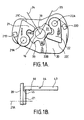
- a latch mechanism 10 including a body 11 which supports various components of the latch mechanism 10 as indicated below.
- Latch mechanism 10 further includes a claw 12 pivotally mounted about axis 13 on the body 11.
- Claw 12 acts to secure an associated door (not shown) in a closed position via a striker pin 14 attached to the door aperture. Rotation of the claw 12 in an anticlockwise direction about axis 13 when viewing Fig. allows release of the striker pin 14, thus enabling opening of the associated door.
- the claw 12 is held in a closed position by a pawl 15, only part of which is shown in dotted profile in Fig.1 for clarity.
- Pawl 15 is pivotally mounted on body 11 and can rotate about axis 16.
- Claw 12 can be held in a first safety position (not shown) when pawl 15 engages first safety abutment 17.
- Pawl lifter 20 is generally flat and lies in a plane parallel to pawl 15, to which it is rotationally secured. When viewing Fig.1 pawl 15 is obscured by pawl lifter 20. Clearly, pawl lifter 20 also rotates about axis 16.
- Inside lock link 21 and outside lock link 22 are mounted for movement with the pawl, in this case they are each individually pivoted about respective axes 21a and 22a on pawl lifter 20.
- inside lock link 21 and outside lock link 22 are identical and each have respective cam followers 21b and 22b and release abutments 21c and 22c.
- Inside lock link 21 and outside lock link 22 are each biased in a clockwise direction when viewing Fig. 1 such that the respective cam followers 21b and 22b contact cam 30.
- Cam 30 is capable of rotating independently from pawl lifter 20 about axis 16.
- Cam 30 has three lobes 31, 32 and 33 and two levers 34, and 35 shown diagrammatically for clarity.
- Lobes 31, 32, 33 and levers 34 and 35 are all rotationally fast with cam 30.
- cam 30 can at least be rotated to the various positions as described below by a power actuator (not shown) such as a DC motor or preferably a stepper motor.
- Outside release lever 40 is pivotedly mounted about axis 41.
- Inside release lever 43 (shown diagrammatically in Fig.lb) is pivotedly mounted about axis 44.
- Fig. 1 shows the door latch mechanism in a super lock condition, that is to say operation of the outside release lever 40 or inside release lever 43 does not allow unlatching of the mechanism.
- outside release lever 40 were to be operated by being rotated in a clockwise direction about axis 41, abutment 42 would pass release abutment 22c of outside lock link 22 without contact (note that outside release lever 40 is in the same plane as outside lock link 22).
- inside release lever 43 when operated by being rotated in an anticlockwise direction about axis 44 when viewing Fig.1b, would cause abutment 45 to pass release abutment 21c of inside lock link 21 (see especially Fig.1).
- Fig.2 shows the door latch mechanism 10 in a locked position with the child safety feature on.
- cam 30 has been rotated 30 degrees in an anticlockwise direction when compared to Fig. 1.
- the inside lock link 21 and outside lock link 22 are in the same position when compared with Fig.1 since neither of the cam followers 21b or 22b have, at this stage, ridden up any of the lobes 31, 32 or 33 of the cam 30.
- lever 34 has been rotated to a position whereby operation of the inside release lever 43 in an anticlockwise direction when viewing Fig.1b would cause abutment 46 to contact lever 34 and rotate cam 30 to the position shown in Fig.3.
- inside release lever 43 does not unlatch the mechanism but only operates to unlock the door (see below).
- This method of being able to override and open a locked door which has the child safety on is especially important in an emergency situation whereby a passer-by can effect access to the inside door handle (eg by breaking the door window glass), operate the inside door handle to unlock the door, then operate the outside door handle to open the door and then remove the child from the car.
- Fig.3 shows the door latch mechanism 10 in an unlocked condition with the child safety feature on.
- the cam 30 has been rotated sufficiently (either by operating the inside release lever when the cam was in the position shown in Fig.2 or by independent rotation of the cam directly eg by a power actuator) such that cam follower 22b has ridden up cam lobe 32 resulting in anticlockwise rotation of outside lock link 22.
- abutment 42 contacts release abutment 22c causing the pawl lifter 20 as a whole to rotate anticlockwise when viewing Fig.3 and releasing the pawl 15 and allowing the claw 12 to open.
- Stop 22d limits the anticlockwise rotation of outside lock link 22.
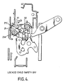
- Fig.4 shows the door latch mechanism 10 in a locked condition with the child safety feature off.
- the cam 30 has been rotated 90 degrees in an anticlockwise direction when compared with Fig.1.
- cam follower 22b being situated between cam lobes 32 and 33 thus ensuring that operation of outside release lever 40 does not release the latch mechanism.
- the rotation of the cam 30 has caused cam follower 21b to ride up cam lobe 31 causing inside lock link 21 to rotate anticlockwise about axis 21a.
- abutment 21c of inside lock link 21 is contacted by abutment 45 of inside release lever 43 when it is operated.
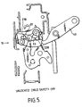
- Fig.5 shows the door latch mechanism 10 in an unlocked position with the child safety feature off. It can be seen that the cam has been rotated (either by operating the inside release lever when the cam was in the position shown in Fig.4 or by independent rotation of the cam directly eg by a power actuator) such that abutment 22b now rests on lobe 33 allowing operation of the outside release lever 40 to unlatch the latch mechanism as described above. Furthermore abutment 21b remains in contact with lobe 31 thus ensuring that operation of the inside release lever also unlatches the door mechanism.
- Fig.6 shows the door latch mechanism 10 in a released position. This is achieved by rotation of cam 30 in a anticlockwise direction which allows contact between corresponding lost motion abutments (not shown) on the pawl lifter 20 and cam 30. Such lost motion abutments allow the cam 30 to rotate the pawl lifter 20 to release the door latch mechanism independently of the operation of the outside release lever 40 or the inside release lever 43.
- inside and outside lock links can be mounted directly on the pawl.
Landscapes
- Health & Medical Sciences (AREA)
- Child & Adolescent Psychology (AREA)
- Lock And Its Accessories (AREA)
- Control Of Vending Devices And Auxiliary Devices For Vending Devices (AREA)
Claims (25)
- Schließmechanismus (10) mit einem Gehäuse (11), einer Klinke (15), die beweglich in dem Gehäuse angebracht ist, um einen Riegel (12) freizugeben, wobei wenigstens ein inneres oder ein äußeres Verriegelungselement (21, 22) so angebracht ist, daß es zwischen einer ersten Stellung, in der die Betätigung einer zugehörigen Freigabeeinrichtung (43, 40) die Bewegung der Klinke verursacht, um den Riegel freizugeben, und einer zweiten Stellung, in der die Betätigung der zugehörigen Freigabeeinrichtung keine Bewegung der Klinke verursacht, bewegt werden kann, dadurch gekennzeichnet, daß das wenigstens eine Verriegelungselement für eine Bewegung mit der Klinke so angebracht ist, daß die Bewegung der Klinke zwangsläufig mit einer Bewegung des Verriegelungselements einhergeht.
- Schließmechanismus nach Anspruch 1, bei dem die Klinke drehbar in dem Gehäuse angebracht ist.
- Schließmechanismus nach Anspruch 1 oder 2, bei dem ein Klinkenheber (20) mit einer Klinke verbunden ist und das wenigstens eine Verriegelungselement auf dem Klinkenheber angebracht ist.
- Schließmechanismus nach einem der vorhergehenden Ansprüche, bei dem das wenigstens eine Verriegelungselement so angebracht ist, daß es sich mit der Klinke (15) um eine gemeinsame erste Achse (16) drehen kann.
- Schließmechanismus nach einem der vorhergehenden Ansprüche, bei dem das wenigstens eine Verriegelungselement für eine Drehbewegung zwischen seiner ersten und seiner zweiten Stellung um eine zweite Achse drehbar angebracht ist.
- Schließmechanismus nach Anspruch 5, wenn dieser von Anspruch 3 abhängt, wobei die Drehung des wenigstens einen Verriegelungselements um die zweite Achse relativ zu dem Klinkenheber erfolgt.
- Schließmechanismus nach einem der vorhergehenden Ansprüche, bei dem das innere und das äußere Verriegelungselement beide so angebracht sind, daß die Bewegung der Klinke zwangsläufig mit einer Bewegung beider Verriegelungselemente einhergeht.
- Schließmechanismus nach Anspruch 7, bei dem das innere und das äußere Verriegelungselement beide so angebracht sind, daß sie sich mit der Klinke um eine gemeinsame erste Achse drehen.
- Schließmechanismus nach Anspruch 8, bei dem die Drehung des inneren oder des äußeren Verriegelungselements um die gemeinsame erste Achse zwangsläufig mit einer entsprechenden Drehung des jeweils anderen Verriegelungselements um die erste Achse einhergeht.
- Schließmechanismus nach einem der vorhergehenden Ansprüche, bei dem das Weiterschalten eines Nockens (30) eine Bewegung des wenigstens einen Verriegelungselements zwischen seiner ersten und seiner zweiten Stellung bewirkt.
- Schließmechanismus nach Anspruch 10, bei dem der Nocken zum Weiterschalten drehbar angebracht ist.
- Schließmechanismus nach Anspruch 11, wenn dieser von Anspruch 2 abhängt, wobei der Nocken koaxial mit der Klinke drehbar angebracht ist.
- Schließmechanismus nach einem der Ansprüche 10 bis 12, bei dem der Nocken wenigstens zwei Nockenbuckel (31, 32, 33) umfaßt, die das wenigstens eine Verriegelungselement in der ersten oder in der zweiten Stellung positionieren, wobei die wenigstens zwei Nockenbuckel durch ein Nockental getrennt sind, welches das wenigstens eine Verriegelungselement in der jeweils anderen von der ersten und der zweiten Stellung positioniert.
- Schließmechanismus nach einem der Ansprüche 10 bis 13, bei dem das Weiterschalten des Nockens die Bewegung sowohl des inneren als auch des äußeren Verriegelungselements bewirkt.
- Schließmechanismus nach einem der Ansprüche 10 bis 14, bei dem der Nocken mehrere Buckel hat.
- Schließmechanismus nach einem der Ansprüche 10 bis 15, bei dem die Freigabeeinrichtung den Nocken weiterschalten kann, um wenigstens eines der Verriegelungselemente zwischen der ersten und der zweiten Stellung zu bewegen.
- Schließmechanismus nach Anspruch 16, bei dem die Freigabeeinrichtung den Nocken weiterschalten kann, um wenigstens eines der Verriegelungselemente von seiner zweiten Stellung in seine erste Stellung zu bewegen.
- Schließmechanismus nach einem der vorhergehenden Ansprüche, bei dem die Bewegung des wenigstens einen Verriegelungselements zwischen seiner ersten und seiner zweiten Stellung durch einen Stellmotor bewirkt wird.
- Schließmechanismus nach einem der vorhergehenden Ansprüche, bei dem die Klinke durch einen Stellmotor bewegt werden kann, um den Riegel freizugeben.
- Schließmechanismus nach Anspruch 19, wenn dieser von Anspruch 18 abhängt, wobei der Stellmotor, der den Nocken weiterschaltet, derselbe Stellmotor ist, der die Klinke bewegt.
- Schließmechanismus nach Anspruch 20, bei dem der Stellmotor den Nocken so antreibt, daß ein Anschlag an dem Nocken funktionsmäßig mit einem an der Klinke fest angebrachten Anschlag zusammenwirkt, um den Schließmechanismus freizugeben.
- Schließmechanismus nach einem der vorhergehenden Ansprüche mit einem Satz von Betriebsarten, wobei jede Betriebsart einander abwechselnde Ein/Aus-Zustände hat, wobei der Satz von Betriebsarten wenigstens einen Verriegelungsmodus oder einen Superverriegelungsmodus und wenigstens einen Kindersicherungsmodus oder einen Freigabemodus hat, und wobei die Änderung des Schließmechanismus zwischen einander abwechselnden Zuständen von jeder der wenigstens zwei Betriebsarten des Satzes von Betriebsarten durch einen einzigen Stellmotor bewirkt wird.
- Schließmechanismus nach Anspruch 22, bei dem der Satz von Betriebsarten den Verriegelungsmodus und den Superverriegelungsmodus und wenigstens den Kindersicherungsmodus oder den Freigabemodus umfaßt.
- Schließmechanismus nach Anspruch 22 oder 23, bei dem der Satz von Betriebsarten wenigstens den Verriegelungsmodus oder den Superverriegelungsmodus und sowohl den Kindersicherungsmodus als auch den Freigabemodus umfaßt.
- Schließmechanismus nach einem der vorhergehenden Ansprüche mit einem Satz von Betriebsarten, wobei jede Betriebsart einander abwechselnde Ein/Aus-Zustände hat, wobei der Satz von Betriebsarten einen Kindersicherungsmodus und einen Freigabemodus umfaßt, und wobei die Änderung des Schließmechanismus zwischen einander abwechselnden Zuständen jeder der Betriebsarten durch einen einzigen Stellmotor bewirkt wird.
Priority Applications (2)
| Application Number | Priority Date | Filing Date | Title |
|---|---|---|---|
| EP02017999A EP1277902A1 (de) | 1998-05-06 | 1999-05-06 | Verriegelungsvorrichtung |
| EP02018000A EP1275801A1 (de) | 1998-05-06 | 1999-05-06 | Verriegelungsvorrichtung |
Applications Claiming Priority (3)
| Application Number | Priority Date | Filing Date | Title |
|---|---|---|---|
| GB9809640 | 1998-05-06 | ||
| GB9809640A GB9809640D0 (en) | 1998-05-06 | 1998-05-06 | Latch mechanism |
| PCT/GB1999/001411 WO1999057397A2 (en) | 1998-05-06 | 1999-05-06 | Latch mechanism |
Related Child Applications (2)
| Application Number | Title | Priority Date | Filing Date |
|---|---|---|---|
| EP02017999A Division EP1277902A1 (de) | 1998-05-06 | 1999-05-06 | Verriegelungsvorrichtung |
| EP02018000A Division EP1275801A1 (de) | 1998-05-06 | 1999-05-06 | Verriegelungsvorrichtung |
Publications (2)
| Publication Number | Publication Date |
|---|---|
| EP1084323A2 EP1084323A2 (de) | 2001-03-21 |
| EP1084323B1 true EP1084323B1 (de) | 2003-01-15 |
Family
ID=10831522
Family Applications (3)
| Application Number | Title | Priority Date | Filing Date |
|---|---|---|---|
| EP02018000A Withdrawn EP1275801A1 (de) | 1998-05-06 | 1999-05-06 | Verriegelungsvorrichtung |
| EP99919442A Expired - Lifetime EP1084323B1 (de) | 1998-05-06 | 1999-05-06 | Verriegelungsvorrichtung |
| EP02017999A Withdrawn EP1277902A1 (de) | 1998-05-06 | 1999-05-06 | Verriegelungsvorrichtung |
Family Applications Before (1)
| Application Number | Title | Priority Date | Filing Date |
|---|---|---|---|
| EP02018000A Withdrawn EP1275801A1 (de) | 1998-05-06 | 1999-05-06 | Verriegelungsvorrichtung |
Family Applications After (1)
| Application Number | Title | Priority Date | Filing Date |
|---|---|---|---|
| EP02017999A Withdrawn EP1277902A1 (de) | 1998-05-06 | 1999-05-06 | Verriegelungsvorrichtung |
Country Status (4)
| Country | Link |
|---|---|
| EP (3) | EP1275801A1 (de) |
| DE (1) | DE69904933T2 (de) |
| GB (2) | GB9809640D0 (de) |
| WO (1) | WO1999057397A2 (de) |
Families Citing this family (10)
| Publication number | Priority date | Publication date | Assignee | Title |
|---|---|---|---|---|
| GB0006931D0 (en) | 2000-03-23 | 2000-05-10 | Meritor Light Vehicle Sys Ltd | Latch mechanism |
| GB0009793D0 (en) | 2000-04-25 | 2000-06-07 | Meritor Light Vehicle Sys Ltd | A lock mechanism |
| GB0018102D0 (en) * | 2000-07-25 | 2000-09-13 | Meritor Light Vehicle Sys Ltd | An actuator |
| DE10046731A1 (de) * | 2000-09-21 | 2002-04-11 | Siemens Ag | Kupplungsvorrichtung für Türverriegelungsanlagen |
| WO2002046557A2 (de) * | 2000-12-07 | 2002-06-13 | Witte-Strattec Llc | Schloss mit von einer sperrklinke in einer geschlossen-stellung gehaltenen falle |
| BR0212037A (pt) * | 2002-06-19 | 2004-08-17 | Arvinmeritor Light Vehicle Sys | Atuadores, arranjo de engate, válvulas e relê para uso em veìculos |
| JP4503055B2 (ja) * | 2007-08-29 | 2010-07-14 | 三井金属鉱業株式会社 | ドアロック装置 |
| CA2888051A1 (en) | 2011-10-25 | 2013-04-25 | Dirtt Environmental Solutions, Ltd. | Cam style locks and systems and methods including the same |
| DE102014104073A1 (de) * | 2014-03-25 | 2015-10-01 | BROSE SCHLIEßSYSTEME GMBH & CO. KG | Kraftfahrzeugschloss |
| DE102022122785A1 (de) * | 2021-09-16 | 2023-03-16 | Magna Closures Inc. | Verschlussverriegelung mit unfall-entriegelungsmechanismus mit einem einzigen elektromotor |
Family Cites Families (5)
| Publication number | Priority date | Publication date | Assignee | Title |
|---|---|---|---|---|
| DE4131891A1 (de) * | 1991-09-25 | 1993-04-01 | Bosch Gmbh Robert | Sperrvorrichtung fuer tueren eines kraftfahrzeugs |
| DE4222868A1 (de) * | 1992-07-11 | 1994-01-13 | Bosch Gmbh Robert | Sperrvorrichtung für Türen eines Kraftfahrzeugs |
| DE4307523B4 (de) * | 1993-03-10 | 2004-05-27 | Kiekert Ag | Kraftfahrzeugtürverschluß mit Zentralverriegelungsantrieb |
| DE19530726C5 (de) * | 1995-08-18 | 2009-07-02 | Kiekert Ag | Zentralverriegelungsanlage mit baugleichen Kraftfahrzeugtürverschlüssen |
| DE19631869A1 (de) * | 1996-08-07 | 1998-02-12 | Bosch Gmbh Robert | Kraftfahrzeug-Türschloß oder dergleichen |
-
1998
- 1998-05-06 GB GB9809640A patent/GB9809640D0/en not_active Ceased
-
1999
- 1999-05-05 GB GB9910198A patent/GB2339236B/en not_active Expired - Fee Related
- 1999-05-06 EP EP02018000A patent/EP1275801A1/de not_active Withdrawn
- 1999-05-06 WO PCT/GB1999/001411 patent/WO1999057397A2/en not_active Ceased
- 1999-05-06 EP EP99919442A patent/EP1084323B1/de not_active Expired - Lifetime
- 1999-05-06 EP EP02017999A patent/EP1277902A1/de not_active Withdrawn
- 1999-05-06 DE DE69904933T patent/DE69904933T2/de not_active Expired - Fee Related
Also Published As
| Publication number | Publication date |
|---|---|
| WO1999057397A3 (en) | 2000-01-20 |
| GB2339236A (en) | 2000-01-19 |
| EP1084323A2 (de) | 2001-03-21 |
| DE69904933T2 (de) | 2003-11-06 |
| EP1275801A1 (de) | 2003-01-15 |
| GB9809640D0 (en) | 1998-07-01 |
| EP1277902A1 (de) | 2003-01-22 |
| DE69904933D1 (de) | 2003-02-20 |
| GB2339236B (en) | 2002-04-03 |
| GB9910198D0 (en) | 1999-06-30 |
| WO1999057397A2 (en) | 1999-11-11 |
Similar Documents
| Publication | Publication Date | Title |
|---|---|---|
| US7377557B2 (en) | Scissor mechanism for a latch assembly | |
| EP1136641B1 (de) | Verriegelungsvorrichtung | |
| US6526790B2 (en) | Closing device | |
| JP6051433B2 (ja) | 自動車用ドアロック | |
| US5117665A (en) | Vehicle door lock system | |
| US20070205613A1 (en) | Lock For Doors And Lids On Vehicles | |
| US20060006671A1 (en) | Automobile vehicle lock | |
| EP1507056A2 (de) | Schliessmechanismus | |
| US4998758A (en) | Low effort remote latch actuator | |
| US6142540A (en) | Motor vehicle door lock | |
| EP0942134A2 (de) | Elektrischer Schliessmechanismus mit einer zusätzlichen türinnenseitigen mechanischen Entriegelungseinrichtung | |
| US6082158A (en) | Closing device | |
| US20150115626A1 (en) | Lock for a flap or door | |
| EP1275801A1 (de) | Verriegelungsvorrichtung | |
| CN1746455A (zh) | 闩锁释放机构 | |
| US20050110279A1 (en) | Actuator for a vehicle door latch | |
| US8840154B2 (en) | Motor vehicle door lock | |
| EP1121503B8 (de) | Türverriegelung | |
| CN114080484A (zh) | 机动车门锁 | |
| US6652009B2 (en) | Actuator | |
| US9945161B2 (en) | Lock system for dual vehicle closures | |
| US20030006618A1 (en) | Latch assembly and method of operating such an assembly | |
| EP1245764B1 (de) | Betätigungsvorrichtung eines Fahrzeugtürschlosses | |
| GB2369404A (en) | Latch mechanism with alternate operating modes | |
| EP3029230B1 (de) | Relaismechanismus für fahrzeugschiebetür |
Legal Events
| Date | Code | Title | Description |
|---|---|---|---|
| PUAI | Public reference made under article 153(3) epc to a published international application that has entered the european phase |
Free format text: ORIGINAL CODE: 0009012 |
|
| 17P | Request for examination filed |
Effective date: 20001106 |
|
| AK | Designated contracting states |
Kind code of ref document: A2 Designated state(s): DE FR |
|
| 17Q | First examination report despatched |
Effective date: 20010515 |
|
| GRAG | Despatch of communication of intention to grant |
Free format text: ORIGINAL CODE: EPIDOS AGRA |
|
| GRAG | Despatch of communication of intention to grant |
Free format text: ORIGINAL CODE: EPIDOS AGRA |
|
| GRAG | Despatch of communication of intention to grant |
Free format text: ORIGINAL CODE: EPIDOS AGRA |
|
| GRAH | Despatch of communication of intention to grant a patent |
Free format text: ORIGINAL CODE: EPIDOS IGRA |
|
| RAP1 | Party data changed (applicant data changed or rights of an application transferred) |
Owner name: ARVINMERITOR LIGHT VEHICLE SYSTEMS (UK) LTD |
|
| GRAH | Despatch of communication of intention to grant a patent |
Free format text: ORIGINAL CODE: EPIDOS IGRA |
|
| GRAA | (expected) grant |
Free format text: ORIGINAL CODE: 0009210 |
|
| AK | Designated contracting states |
Kind code of ref document: B1 Designated state(s): DE FR |
|
| REF | Corresponds to: |
Ref document number: 69904933 Country of ref document: DE Date of ref document: 20030220 Kind code of ref document: P |
|
| PGFP | Annual fee paid to national office [announced via postgrant information from national office to epo] |
Ref country code: FR Payment date: 20030520 Year of fee payment: 5 |
|
| PGFP | Annual fee paid to national office [announced via postgrant information from national office to epo] |
Ref country code: DE Payment date: 20030626 Year of fee payment: 5 |
|
| ET | Fr: translation filed | ||
| PLBE | No opposition filed within time limit |
Free format text: ORIGINAL CODE: 0009261 |
|
| STAA | Information on the status of an ep patent application or granted ep patent |
Free format text: STATUS: NO OPPOSITION FILED WITHIN TIME LIMIT |
|
| 26N | No opposition filed |
Effective date: 20031016 |
|
| PG25 | Lapsed in a contracting state [announced via postgrant information from national office to epo] |
Ref country code: DE Free format text: LAPSE BECAUSE OF NON-PAYMENT OF DUE FEES Effective date: 20041201 |
|
| PG25 | Lapsed in a contracting state [announced via postgrant information from national office to epo] |
Ref country code: FR Free format text: LAPSE BECAUSE OF NON-PAYMENT OF DUE FEES Effective date: 20050131 |
|
| REG | Reference to a national code |
Ref country code: FR Ref legal event code: ST |