EP1084335B1 - Moteur a pistons - Google Patents
Moteur a pistons Download PDFInfo
- Publication number
- EP1084335B1 EP1084335B1 EP99924799A EP99924799A EP1084335B1 EP 1084335 B1 EP1084335 B1 EP 1084335B1 EP 99924799 A EP99924799 A EP 99924799A EP 99924799 A EP99924799 A EP 99924799A EP 1084335 B1 EP1084335 B1 EP 1084335B1
- Authority
- EP
- European Patent Office
- Prior art keywords
- piston
- pump
- charge
- machine
- injection
- Prior art date
- Legal status (The legal status is an assumption and is not a legal conclusion. Google has not performed a legal analysis and makes no representation as to the accuracy of the status listed.)
- Expired - Lifetime
Links
- 238000002347 injection Methods 0.000 claims abstract description 67
- 239000007924 injection Substances 0.000 claims abstract description 67
- 238000011049 filling Methods 0.000 claims abstract description 4
- 230000007246 mechanism Effects 0.000 claims description 41
- 230000002000 scavenging effect Effects 0.000 claims description 27
- 239000000446 fuel Substances 0.000 claims description 19
- 230000001965 increasing effect Effects 0.000 claims description 19
- 238000002485 combustion reaction Methods 0.000 claims description 17
- 230000006835 compression Effects 0.000 claims description 14
- 238000007906 compression Methods 0.000 claims description 14
- 230000001105 regulatory effect Effects 0.000 claims description 14
- 230000033001 locomotion Effects 0.000 claims description 10
- 238000005461 lubrication Methods 0.000 claims description 9
- 238000013461 design Methods 0.000 claims description 7
- 238000007789 sealing Methods 0.000 claims description 6
- 230000009466 transformation Effects 0.000 claims description 6
- 230000000977 initiatory effect Effects 0.000 claims description 5
- 239000013589 supplement Substances 0.000 claims description 5
- 230000003993 interaction Effects 0.000 claims description 4
- 238000000034 method Methods 0.000 claims description 4
- 239000000203 mixture Substances 0.000 claims description 3
- 230000008569 process Effects 0.000 claims description 3
- 238000005086 pumping Methods 0.000 claims description 3
- DGAQECJNVWCQMB-PUAWFVPOSA-M Ilexoside XXIX Chemical compound C[C@@H]1CC[C@@]2(CC[C@@]3(C(=CC[C@H]4[C@]3(CC[C@@H]5[C@@]4(CC[C@@H](C5(C)C)OS(=O)(=O)[O-])C)C)[C@@H]2[C@]1(C)O)C)C(=O)O[C@H]6[C@@H]([C@H]([C@@H]([C@H](O6)CO)O)O)O.[Na+] DGAQECJNVWCQMB-PUAWFVPOSA-M 0.000 claims description 2
- 230000002708 enhancing effect Effects 0.000 claims description 2
- 229910052708 sodium Inorganic materials 0.000 claims description 2
- 239000011734 sodium Substances 0.000 claims description 2
- 230000001502 supplementing effect Effects 0.000 claims description 2
- 238000007664 blowing Methods 0.000 claims 4
- 230000001360 synchronised effect Effects 0.000 claims 4
- 239000002826 coolant Substances 0.000 claims 2
- 238000012432 intermediate storage Methods 0.000 claims 2
- 230000004308 accommodation Effects 0.000 claims 1
- 230000015572 biosynthetic process Effects 0.000 claims 1
- 230000000903 blocking effect Effects 0.000 claims 1
- 230000008602 contraction Effects 0.000 claims 1
- 230000004069 differentiation Effects 0.000 claims 1
- 238000006073 displacement reaction Methods 0.000 claims 1
- 238000009826 distribution Methods 0.000 claims 1
- 238000005516 engineering process Methods 0.000 claims 1
- 238000002955 isolation Methods 0.000 claims 1
- 239000007788 liquid Substances 0.000 claims 1
- 238000004519 manufacturing process Methods 0.000 claims 1
- 238000002844 melting Methods 0.000 claims 1
- 230000008018 melting Effects 0.000 claims 1
- 230000001131 transforming effect Effects 0.000 claims 1
- 239000000567 combustion gas Substances 0.000 abstract 1
- 239000003921 oil Substances 0.000 description 6
- 239000000463 material Substances 0.000 description 5
- 239000000243 solution Substances 0.000 description 5
- 230000008901 benefit Effects 0.000 description 4
- 238000011161 development Methods 0.000 description 4
- 230000018109 developmental process Effects 0.000 description 4
- 229910003460 diamond Inorganic materials 0.000 description 4
- 239000010432 diamond Substances 0.000 description 4
- 238000004364 calculation method Methods 0.000 description 3
- 239000011248 coating agent Substances 0.000 description 3
- 238000000576 coating method Methods 0.000 description 3
- 238000010276 construction Methods 0.000 description 3
- 239000000314 lubricant Substances 0.000 description 3
- 230000009467 reduction Effects 0.000 description 3
- 238000000638 solvent extraction Methods 0.000 description 3
- 238000001816 cooling Methods 0.000 description 2
- 239000000498 cooling water Substances 0.000 description 2
- 239000007789 gas Substances 0.000 description 2
- 238000011160 research Methods 0.000 description 2
- 230000002123 temporal effect Effects 0.000 description 2
- 238000012360 testing method Methods 0.000 description 2
- 206010011376 Crepitations Diseases 0.000 description 1
- 241000321453 Paranthias colonus Species 0.000 description 1
- 208000037656 Respiratory Sounds Diseases 0.000 description 1
- 241000894433 Turbo <genus> Species 0.000 description 1
- 238000010521 absorption reaction Methods 0.000 description 1
- 238000007792 addition Methods 0.000 description 1
- 239000003570 air Substances 0.000 description 1
- 230000004075 alteration Effects 0.000 description 1
- 230000004323 axial length Effects 0.000 description 1
- 230000005540 biological transmission Effects 0.000 description 1
- 239000003054 catalyst Substances 0.000 description 1
- 239000000919 ceramic Substances 0.000 description 1
- 238000005524 ceramic coating Methods 0.000 description 1
- 239000000470 constituent Substances 0.000 description 1
- 238000011109 contamination Methods 0.000 description 1
- 230000001276 controlling effect Effects 0.000 description 1
- 230000003111 delayed effect Effects 0.000 description 1
- 230000000694 effects Effects 0.000 description 1
- 230000008030 elimination Effects 0.000 description 1
- 238000003379 elimination reaction Methods 0.000 description 1
- 238000005265 energy consumption Methods 0.000 description 1
- 230000007613 environmental effect Effects 0.000 description 1
- 238000002474 experimental method Methods 0.000 description 1
- 238000003780 insertion Methods 0.000 description 1
- 230000037431 insertion Effects 0.000 description 1
- 239000010687 lubricating oil Substances 0.000 description 1
- 238000012423 maintenance Methods 0.000 description 1
- 238000002156 mixing Methods 0.000 description 1
- 238000012856 packing Methods 0.000 description 1
- 230000000149 penetrating effect Effects 0.000 description 1
- 230000008439 repair process Effects 0.000 description 1
- 230000029058 respiratory gaseous exchange Effects 0.000 description 1
- 230000000717 retained effect Effects 0.000 description 1
- 238000004088 simulation Methods 0.000 description 1
- 239000000126 substance Substances 0.000 description 1
- 238000012546 transfer Methods 0.000 description 1
Images


Classifications
-
- F—MECHANICAL ENGINEERING; LIGHTING; HEATING; WEAPONS; BLASTING
- F02—COMBUSTION ENGINES; HOT-GAS OR COMBUSTION-PRODUCT ENGINE PLANTS
- F02F—CYLINDERS, PISTONS OR CASINGS, FOR COMBUSTION ENGINES; ARRANGEMENTS OF SEALINGS IN COMBUSTION ENGINES
- F02F1/00—Cylinders; Cylinder heads
- F02F1/18—Other cylinders
- F02F1/22—Other cylinders characterised by having ports in cylinder wall for scavenging or charging
-
- F—MECHANICAL ENGINEERING; LIGHTING; HEATING; WEAPONS; BLASTING
- F02—COMBUSTION ENGINES; HOT-GAS OR COMBUSTION-PRODUCT ENGINE PLANTS
- F02B—INTERNAL-COMBUSTION PISTON ENGINES; COMBUSTION ENGINES IN GENERAL
- F02B33/00—Engines characterised by provision of pumps for charging or scavenging
- F02B33/02—Engines with reciprocating-piston pumps; Engines with crankcase pumps
- F02B33/06—Engines with reciprocating-piston pumps; Engines with crankcase pumps with reciprocating-piston pumps other than simple crankcase pumps
- F02B33/10—Engines with reciprocating-piston pumps; Engines with crankcase pumps with reciprocating-piston pumps other than simple crankcase pumps with the pumping cylinder situated between working cylinder and crankcase, or with the pumping cylinder surrounding working cylinder
- F02B33/12—Engines with reciprocating-piston pumps; Engines with crankcase pumps with reciprocating-piston pumps other than simple crankcase pumps with the pumping cylinder situated between working cylinder and crankcase, or with the pumping cylinder surrounding working cylinder the rear face of working piston acting as pumping member and co-operating with a pumping chamber isolated from crankcase, the connecting-rod passing through the chamber and co-operating with movable isolating member
-
- F—MECHANICAL ENGINEERING; LIGHTING; HEATING; WEAPONS; BLASTING
- F02—COMBUSTION ENGINES; HOT-GAS OR COMBUSTION-PRODUCT ENGINE PLANTS
- F02B—INTERNAL-COMBUSTION PISTON ENGINES; COMBUSTION ENGINES IN GENERAL
- F02B75/00—Other engines
- F02B75/02—Engines characterised by their cycles, e.g. six-stroke
- F02B2075/022—Engines characterised by their cycles, e.g. six-stroke having less than six strokes per cycle
- F02B2075/025—Engines characterised by their cycles, e.g. six-stroke having less than six strokes per cycle two
Definitions
- the present invention relates to a piston machine.
- four-stroke engines can be supplied extra air supply by supplementing the amount of air sucked in through the traditional valve system with air supplied through ports situated and made like the scavenging air ports in a two-stroke engine.
- the indicated method of supply makes possible that the swirling in the combustion chamber can be influenced in a suitable way while at the same time the cooling of the piston tops, cylinder walls, and valves can be increased.
- the air supply may be performed at the termination of both termination of each intake stroke and at the initiation of each exhaust stroke.
- the air supply can furthermore be brought to take place only at the termination of each intake stroke.
- the air supply must be performed by a timing relative to the ordinary valve system of the engine.
- crank and connecting rod mechanisms irrespectively whether the piston drive forces are drawn by the use of traditional crank and connecting rod mechanisms, by the use of a new "double connecting rod mechanism” developed by me, or by mechanisms allowing use of cylindrical piston rods reciprocated directly in the cylinder axis, as e.g. traditional crosshead engines, "crank loop” engines by FICHT GmbH & Co. KG, “twisting piston engines” by Teisen, and engines with the "I-yoke mechanism” developed by me.
- the machine according to US-A-3 789 808 has only a single piston per cylinder and is supplied via an inlet valve with a first charge and is supplemented by an injetation port in the cylinder wall near the botom dead center of the piston with a supplementary charge from the pump chamber of the pump piston, the pump chamber and the short connection duct are associated with a volume increasing the dead volume of the pump.
- the non-rotating internal combustion four-stroke engine having also only a single piston per cylinder is supplied via an inlet valve with a first charge and is supplemented by an injection port in the cylinder wall near the bottom dead center of the piston with a supplementary charge from the pump chamber of the pump piston.
- the pump chamber and a short connection duct are associated with a volume/receiver increasing the dead volume of the pump.
- the pump chamber is provided with a simple non-return valve.
- a piston machine comprising a piston arranged in a cylinder in order to create a working chamber, and at least one pump chamber, which cylinder is provided with at least one injection port and a further injection port arranged in the cylinder wall and connecting the pump chamber with a receiver, said machine only has one piston in each cylinder, wherein the piston by reciprocation sucks in a charge/charges of which at least one is a supplementary aftercharge to the charge/charges supplied at the ordinary suction valve, scavenging port and/or by another/other supply system/systems and may be a supplement hereto of the same or other kind, supplied to the working chamber of the combined working and pumping piston itself by being blown through said at least one injection port formed in its cylinder wall only for this said port being placed close to the position taken by the top of piston when the piston is in its bottom dead point and at least in a position that it becomes completely exposed by the piston top, that said one or more injection ports by one annular duct are mutually connected
- the specific arrangement of the receiver which has a dead volume makes it possible to increase the dead volume of the pump and the volume of the duct connections extended to the injection ports to a volume implying.
- the charge is compressed to the pressure which is most suitable for the application of the machine at the rpm and load preferred in use, which makes the machine advantageous for functioning in a range only slightly deviating from the rpm and the load at which it is intended to operate with the associated receiver, but which only by the replacing of this can be adapted to another rpm and load range without an unsuitable increase of loss caused by throttling at the intake and loss by compression and injection occurring.
- a piston machine as disclosed in claim 5 results in that the charge has to be collected and stored while the piston of the machine by its reciprocating from its top dead point toward its bottom dead point performs suction of the succeeding charge and until the piston top by its stroke initiates the exposing of the injection ports formed in the working cylinder and commences injection of the charge previously compressed in the pump, which progress of process suitably is performed in the machine in that immediately after the check valve disposed in the suction duct and the receiver determining the magnitude of the charge pressure and associated with the dead volume of the pump there is inserted a likewise pressure differential controlled check valve in the inlet opening of the exhaust duct immediately before a receiver associated with this duct, the receiver advantageously possibly being a combined receiver and pressure regulator retaining the compressed charge in the receiver until it by the exposure of the injection port/ports by the piston is injected to the working cylinder of the piston, which is a design, though requiring two check valves, implies the advantage of the piston having a greater skirt diameter and in addition, because of the outward collaring of the piston, has
- a piston machine makes use of two different types of yoke-mechanisms. Both mentioned mechanisms are advantageous in that they ensure an exact piston reciprocation in the cylinder axis, besides performing sinusoidal (harmonic) piston strokes by evenly performed rotations, which in a simple way makes possible a complete (100 %) outbalancing of all reciprocating masses in the cylinder axis, and for the number of cylinders mostly used also a complete (100 %) outbalancing of the masses moved perpendicularly to the cylinder axis without the use of balancing mechanisms, and besides, what is important for the realisation of the machine, that the "Scottish yoke mechanism” reduces the lateral pressure on the piston rod and the piston to only being 50 % of that generated by a crank and connecting rod mechanism used for the same purpose, while the "I-yoke mechanism” operates without any generation of lateral pressure on the piston rod and the piston, of which especially the piston, being isolated from the crank disc chamber is not supplied with lubricating agent herefrom in
- the amorphous diamond film developed by Sandia Laboratories which can be coated at room temperature, is temperature resistant until 800 degrees Celsius, besides being stress-free, safe against crackles, having a hardness corresponding to 90 % of that of crystalline diamond, being resistant against to almost all chemicals, and, very important for the purpose, having a very low coefficient of friction, or by using light, temperature resistant materials for the piston rings, alternatively the piston and/or the cylinder, having or which may be provided with smooth surfaces, for example of ceramic type, which design and materials interacting with automatically controlled, combined receivers and pressure regulators make the machine capable of in a hitherto unattainable way to be advantageous, in relation to its developed torque and yield, in being used as a light and compact automotive four-stroke engine or as a single-stage compressor, particularly made like a "boxer" engine with two piston sets per yoke disposed in the same cylinder axis, projecting to both sides of the common yoke, and furthermore as engine because of the supplementary aftercharge to eliminate or limit the need
- Piston machine may be embodied according to claim 9.
- the charge in engines with direct fuel injection is atmospheric air, which, if necessary for lubrication of the isolated piston part, may be supplied with a small oil fog content, and in engines with indirect fuel supply, either established by a fuel injection system associated with the supply duct of the aftercharge pump or a carburettor allowing the charge to be a suitable mixture of air, fuel and oil.
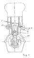
- Fig. 1 shows schematically how a four-stroke engine with a traditional crank-connecting rod mechanism 17' provided with the stepped piston 1 has been provided intake ports 1' which by supply ducts are connected with the annular chamber 8 formed under the relatively short piston top part because of the stepping of the piston.
- the chamber 8 forms an air pump chamber which through the check valve 2' and a supply duct by the movement of the piston from BDC to TDC can suck in fresh air shown by the supply arrow designated A.
- the receiver may suitably be provided with a regulating mechanism capable of regulating the volume of the receiver for receiving air, whereby it becomes capable of regulating the pressure of the air compressed in the air pump chamber.
- Receivers of this kind may e.g. be a cylinder with a piston which, placed on a piston rod that may be moved in and out of the cylinder by a mechanism, is capable of reducing or increasing the volume available for receiving the compressed air.
- Receivers that may be regulated in volume may interact with juxtaposed pump chambers, e.g. in in-line engines, are made as one cylinder with one through-going piston rod which, passed through partitioning walls with stuffing box arrangements, carries a plurality of piston discs, one in each of the chambers into which the partitioning walls divide the cylinder to contain.
- Each chamber in the cylinder is connected with a duct to their respective interacting pump chamber.
- the connecting duct is of course disposed at one end of their chambers which are kept clear of the piston irrespectively of the adjustment of the piston.
- Engines with plural cylinders may also have their air pump chambers connected with a receiver common to all chambers, e.g. of the type first mentioned with an adjustable volume, or to a receiver with a sufficiently large fixed volume.
- the four-stroke engine shown in Fig. 1 is of the kind receiving extra air supply both at the end of each intake stroke and in the beginning of each exhaust stroke. If such an engine is provided with a rotary valve like the rotary valve 3" shown and placed in the same position as in Fig.
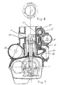
- the sketch Fig. 2 like Fig. 1, is an engine with traditional crank and connecting rod mechanism provided with a stepped piston. For the components forming a part of it, the sketch is numbered as Fig. 1.
- the engine can be provided with a regular aftercharge.
- the rotary valve may of course be given the same mechanisms for "twisting” or "turning".
- the sketch Fig. 3 illustrates a four-stroke engine with "double connecting rod mechanism" 50+50 described in Danish patent application no. 1278/96 with priority date 13 November 1996.
- double connecting rod mechanism causes relief of the lateral pressure on the stepped piston 1 simultaneously with the occurrence exactly in the piston axis of an absorption and a transfer of the yielded drive forces and the occurring inertial forces to the piston pin 102, which results in that the stepped piston has been given a hollow, cylindrical piston rod fixed, possibly moulded. in the piston, the piston rod carrying a fitting at the end receiving the piston pin.
- the engine illustrated in Fig. 3 is further provided with the check valve 2" and an extra receiver 10' which may be with constant or adjustable volume and of course, besides that, with ducts for supply and discharge.
- the injection ports may be made high or placed higher over the piston top level at the reversal of the piston in BDC, because the injection ports are disposed closely to the external cylinder side of the rotary valve and therefore, when they are closed by the rotary valve, only increase the combustion and pump chamber with such a small extra volume that their presence is inessential for the reduction of the effective length of stroke and because they are only opened and kept open at times where injection of extra air is desired.
- four-stroke engines with injection ducts have to be given piston rings which are secured against turning in their annular fastening so that they hereby engage the port apertures with their ends.
- the circumferential division of the cylinder wall by port apertures should be performed so that about 25 % of the cylinder wall remain circumferentially evenly distributed for supporting the piston rings.
- a throttle valve in the engine intake to the pump chamber so that a further adjusting of the air amount sucked in and hereby also of the compression pressure may be performed.
- Fig. 4 is a sketch showing close to reality how a four-stroke engine with pump arrangement of its own, but without rotary valve, can be provided fresh air at the initiation of the exhaust stroke and extra fresh air at the termination or finishing of the intake stroke through low injection ports disposed immediately over the piston top when the piston reverses in BDC.
- the engine in Fig. 4 is directly comparable with the engine in enclosed Fig. 5 which without injection ports functions as a traditional four-stroke engine.
- the additions are the injection ports 5+5' and 5" with their associated supply ducts 6+6' and 6" connecting them with the very low space which is left of the pump chamber when the piston reverses in BDC, which space and supply ducts through a narrow, vertical connection 7 associating them with the active end of the annular chamber which, as it appears from the sectional view uppermost on the sketch, appears by inserting a preferably cylindrical spindle/tensile rod 9 in the centre axis of a cylindrical, tubular body extending past several combustion chambers, the rod 9 to be imparted a controlled axial movement by a regulating mechanism, e.g.
- Insertion of the bottom piece with the sealing guide causes that a very little amount of oil can penetrate up and cause pollution by being supplied to the combustion chamber absorbed in the air compressed in the pump chamber.
- the good sealing down against the crank disc chamber combined with the pump chamber prevents combustion residues in penetrating into the crank disc chamber and polluting the oil used there which thus may be used for more running hours without causing wear on the components working in the crank disc chamber.
- the sealing guide By its relatively large axial length, the sealing guide causes an even further secured guiding of the pistons at the reciprocation of these in the piston axis, so that the lateral pressure on the pistons already removed in practice is reduced and by selection of suitable materials for cylinder linings, pistons and piston rings makes a lubrication free movement of the parts abutting on the cylinder wall conceivable, and at least makes possible that lesser contaminating lubricating agents may be used in a small scale.
- engines with injection ports and I-yoke mechanisms like the four-stroke engine sketched in Fig. 6, advantageously can be constructed with two pistons which at their piston rods at each side of the I-yoke are fastened to this and thereby is brought to work in the same common piston rod axis
- the engines may be provided with two guides in this and hereby ensure such a guiding of the pistons that they in practice reciprocate exactly in their piston axis, whereby only their piston rings are pressed against the cylinder wall.
- the engine according to Fig. 4 as Otto engine is supplied a supplementary amount of air which, depending on the adjusting of the receiver, is from 3,86% to 18,07% greater than the amount supplied through the valve system, while in the engine, made as diesel engine, it may be provided a supplementary amount of air which is from about 6% to about 12% greater than the amount supplied through the valve system.
- Ford terminated their tests with the port controlled Ford-Orbital two-stroke engine.
- Toyota continued their tests with a petrol two-stroke with scavenging ports and whole 4 top-disposed exhaust valves.
- Mercedes-Benz continued their experiments with a diesel two-stroke without ports, but with 2 intake and 2 exhaust valves placed at the top. Both engines troubled by the increased load of doubling the strokes compared with a four-stroke engine. Besides, just as complicated and costly to produce as four-stroke engines and further costly by having to be provided with air compressors for yield reasons.
- GV's two-stroke engine is basically provided with a simple and cheap port control being improved with respect to scavenging by an increased scavenging air volume and further improved by being performed with oilless scavenging air.
- the basic port control is amplified with just as simple and cheap arrangement of aftercharge air ports, the opening and closing of which being governed by an uncomplicated and cheap rotary valve with a simple duct design leading the access of the charge air previously compressed and accumulated in a receiver to the aftercharge ports.
- GV's two-stroke engine works without use of costly turbos or compressors, in addition, irrespectively of the cylinder number it is computer controlled capable of providing itself with aftercharge air with a volume suitable for the momentary rpm and load of the engine, which minimises the pump work.
Landscapes
- Engineering & Computer Science (AREA)
- Chemical & Material Sciences (AREA)
- Combustion & Propulsion (AREA)
- Mechanical Engineering (AREA)
- General Engineering & Computer Science (AREA)
- Combustion Methods Of Internal-Combustion Engines (AREA)
- Lubrication Of Internal Combustion Engines (AREA)
- Reciprocating Pumps (AREA)
- Cylinder Crankcases Of Internal Combustion Engines (AREA)
- Compressor (AREA)
- Valve Device For Special Equipments (AREA)
- Compressors, Vaccum Pumps And Other Relevant Systems (AREA)
Claims (17)
- Machine à piston comprenant un piston (1) logé dans un cylindre pour créer une chambre de travail, et au moins une chambre de pompe (8), lequel cylindre est doté d'au moins une lumière d'injection (1") et d'une autre lumière d'injection (7) ménagée dans la paroi du cylindre (4) et raccordant la chambre de pompe (8) à un récepteur (11), ladite machine n'ayant qu'un piston dans chaque cylindre, machine selon laquelle le piston (1), par déplacement alternatif aspire une charge/des charges d'alimentation dont au moins une est une alimentation supplémentaire dite suralimentation par rapport à la charge/aux charges fournies au niveau de la soupape d'aspiration ordinaire, de la lumière de balayage et/ou par un autre système/d'autres systèmes d'alimentation, et peut être un complément de cette ou ces dernières de même type ou d'un genre différent, fournie à la chambre de travail du piston (1) de travail et de pompage combiné en étant soufflée par au moins une lumière d'injection (1") ménagée dans la paroi du cylindre (4) uniquement du fait que cette dite lumière est placée à proximité de la position adoptée par le sommet du piston lorsque le piston est à son point mort bas, et au moins dans une position dans laquelle elle est totalement exposée par le sommet du piston, et que ladite lumière ou plusieurs desdites lumières d'injection (1", 5, 5', 5") sont mutuellement raccordées, par un conduit annulaire, au moins à un conduit d'échappement court (6) les raccordant au volume mort dans la pompe qui comprime la charge supplémentaire, lequel volume mort a été minimisé, le récepteur (11') étant raccordé au conduit d'échappement (6, 6', 5"), un clapet de non retour commandé par pression différentielle (2') étant placé dans ce conduit d'échappement près du volume mort de la pompe (8), et les récepteurs (11', 10') utilisés dans cette machine étant conçus de telle sorte qu'il est possible d'augmenter ou de réduire leurs volumes individuels par réglage manuel.
- Machine à piston selon la revendication 1, caractérisée en ce que lesdits récepteurs (11', 10') sont conçus de telle sorte que tous les récepteurs prévus dans une machine à multiples cylindres pour ses cylindres individuels dans le même but et de préférence sur le même axe, sont réglés par un système de réglage afin de présenter exactement le même volume et ainsi permettre que la machine, sans autres opérations, puisse être réglée pour générer une pression de chargement qui est appropriée pour que la machine fonctionne à un certain régime de rotation dans une certaine plage de charges.
- Machine à piston selon les revendications 1 et 2, caractérisée en ce que tous les récepteurs (11', 10') utilisés dans une machine sont conçus de telle sorte que pendant le fonctionnement de la machine et sous un contrôle approprié de microprocesseurs, ils enregistrent les demandes de la machine, et à l'aide d'un système de commande informatique, ils peuvent régler automatiquement, de manière à augmenter ou réduire, par voie mécanique, hydraulique ou pneumatique la capacité du volume de telle sorte qu'ils augmentent les volumes morts de chaque chambre de pompe, ce qui permet d'obtenir des récepteurs et des régulateurs de pression (11', 10') combinés qui, sans mécanisme de papillon des gaz associé au conduit d'aspiration pour limiter la charge d'alimentation s'écoulant jusqu'à la pompe (8), permettent de réguler la pression de chargement qui s'accumule dans la pompe (8) par compression pour assurer l'avance à l'injection et injecter la charge supplémentaire, et ainsi la puissance de cette charge supplémentaire injectée dans la machine, en vue d'assurer le réglage le plus approprié de la charge et du régime de rotation immédiats, ce qui est très important pour réduire les pertes de pompe dues à l'aspiration et à la compression et, en outre, parce que la capacité de régulation de la machine la rend particulièrement appropriée pour des applications dans lesquelles elle est soumise à une variation du régime de rotation et des charges.
- Machine à piston selon les revendications 1, 2 et 3, caractérisée en ce qu'elle utilise un mécanisme traditionnel de bielle de raccordement au vilebrequin (17") pour la transformation de la force et en ce que la chambre de pompe (8) est formée par l'utilisation d'un piston étagé (1) avec une jupe de piston dont le diamètre est inférieur à la tête du piston se refermant contre la chambre de travail placée au-dessus de ce dernier et également par son diamètre supérieur par rapport à la jupe de piston se refermant contre la chambre de pompe annulaire (8) située en dessous, formée par la différence de diamètre entre la jupe de piston et la paroi du cylindre (4), dans le fond duquel la jupe de piston s'étend et est animée d'un mouvement alternatif dans le cylindre adapté pour son diamètre, la chambre de vilebrequins sous-jacente étant ainsi fermée avec étanchéité, ce mode de réalisation utilisant des composants connus et étant donc simple à fabriquer, malgré la pression latérale exercée sur le piston du fait de la transformation de la force, du fait de la contraction par rapport à la tête du piston, du fait que la jupe de piston offre des possibilités réduites de déflexion et de fixation pour les bielles de raccordement d'une longueur appropriée et du fait du poids accrû du piston (1) par rapport à un piston traditionnel, qui résulte en un type de machine présentant une hauteur globale relativement importante par rapport à un moteur traditionnel, et, compte tenu des autres inconvénients mentionnés, qui résulte en une machine n'étant adaptée que pour des applications dans lesquelles elle fonctionne avec une charge modérée et régulière et un régime de rotation régulier.
- Machine à piston selon les revendications 1, 2 ou 3, caractérisée en ce qu'elle utilise un vilebrequin traditionnel et un mécanisme de bielle de raccordement (17") pour la transformation de sa force et en ce que la chambre de pompe (8) est formée par l'utilisation d'un piston étagé (1'), dont la partie supérieure est formée comme un piston de travail traditionnel, et assurant au niveau de sa tête de piston, une fermeture étanche contre la chambre de travail située au-dessus de ce dernier, et est formée en outre par une jupe de piston étendue, qui au niveau du bord de son fond présente un évasement orienté vers l'extérieur qui au niveau de sa partie de dessous assure une fermeture étanche contre le carter du moteur situé en-dessous, et qui, au niveau de son bord latéral orienté vers le haut assure une fermeture étanche contre la chambre de pompe annulaire formée entre la jupe de piston et le cylindre de la pompe, le piston, dans cette chambre de pompe annulaire, par son déplacement alternatif, comprimant la charge aspirée à une pression de charge maximale dont le point supérieur se situe au moment où le piston de travail (1') atteint sa position de point mort haut.
- Machine à piston selon les revendications 1, 2 ou 3, caractérisée en ce que sa chambre de pompe est annulaire et formée par l'interaction entre un piston cylindrique léger et court (1) non étagé, son cylindre et une tige de piston (2) cylindrique légère, creuse et débordante, reliée de manière rigide au piston (1), et une partie de fond de cylindre avec une douille de guidage et de fermeture combinée (13) placée en son centre, dans laquelle passe la tige de piston (2) pour pénétrer dans un carter de moteur, lubrifié à l'huile sous pression, situé au dessous, et fixé à un élément à chape (14) s'étendant de manière perpendiculaire par rapport à la tige de piston et faisant partie d'un mécanisme de type « excentrique Scotch « ou d'un mécanisme de type « excentrique en forme de I » qui constitue le mécanisme de transformation de la force et transforme le mouvement alternatif du piston (1) en rotation ou vice et versa.
- Machine à piston selon les revendications 1, 2, 5 ou 6, caractérisée en ce que le piston utilisé dans la machine est un piston étagé (1') avec un système récepteur et qui comprend un mécanisme de type « excentrique Scotch » ou un « excentrique en forme de I » ce qui permet de supprimer l'inconvénient de devoir lubrifier les pièces du piston situées indépendamment au-dessus de l'évasement orienté vers l'extérieur dans la machine utilisée comme compresseur ou moteur à quatre temps, en partie du fait que la pression latérale exercée sur le piston (1') est réduite ou supprimée et également du fait que le carter du moteur peut ainsi être lubrifié par une huile sous pression, de même que la paroi inférieure du cylindre peut être lubrifiée le lubrifiant est repoussé contre le dessous du piston, ce qui est avantageux pour éliminer la chaleur de ce dernier, mais ne permet pas de ce fait d'utiliser cette machine comme un moteur à deux temps.
- Machine à piston selon les revendications 1 à 7, caractérisée en ce qu'elle est fabriquée comme un moteur à deux temps ou à quatre temps qui, indépendamment du fait que la charge supplémentaire soit comprimée ou non dans une chambre de pompe (8) permettant l'alimentation immédiate ou nécessitant un stockage intermédiaire avant l'alimentation de la chambre de service, est pourvu d'un système de récepteur élaboré, selon lequel entre le récepteur (10', 11') - qui est, de manière appropriée, un récepteur et un régulateur de pression combiné, à commande automatique - et la lumière/les lumières d'injection (1", 5, 5', 5"), se trouve une soupape rotative (3") dont la rotation est synchronisée pour suivre le régime du moteur et qui peut être couplée pour tourner selon un régime semblable ou égal à la moitié de ce régime, ladite machine étant formée, en outre, avec un système de conduits s'étendant; de manière appropriée, sur la périphérie cylindrique du rotor et ici, par son extension angulaire polaire et son positionnement peut, dans la période pendant laquelle le piston a exposé la lumière/les lumières d'injection (1", 5, 5', 5"), en fonction de la position du piston (1, 1'), contrôler le moment où le conduit ouvre le raccordement entre le récepteur (10', 11') et la lumière/les lumières d'injection (1", 5, 5', 5") et initier ainsi l'injection de la charge supplémentaire en réduisant la pression de la charge stockée dans le récepteur (10') laquelle injection et lequel soufflage se poursuivent jusqu'à ce que le raccord du conduit se ferme ou que le piston (1, 1') ferme la lumière/les lumières d'injection (1", 5, 5', 5") par son déplacement vers le haut à partir du point mort bas.
- Machine à piston selon les revendications 1 à 8, caractérisée en ce que la machine est un moteur à deux temps avec un système de récepteur et de soupape rotative, dont la soupape rotative (3") est synchronisée pour tourner au même régime de rotation que le moteur, et en ce que le moteur est aussi pourvu de lumières de balayage et d'échappement avec une ou des lumières d'injection (1") qui, en raison du contrôle du moment d'injection effectué par la soupape (3") sans avoir d'effet sur la progression du processus dans le moteur, sont ménagées à un niveau situé légèrement au-dessus de l'ouverture de la lumière d'échappement, et en ce que la soupape rotative (3") est pourvue d'un système de conduit avec une section traversante relativement grande qui, dès que le piston (1') a recouvert l'ouverture de la lumière d'échappement pendant son mouvement alternatif à partir du point mort bas, s'ouvre brusquement et se referme rapidement pour terminer l'injection de la suralimentation qui, du fait de la période d'injection très brève, a reçu la pression de charge requise, lequel système permet d'assurer que le moteur est alimenté selon une quantité élevée particulièrement appropriée.
- Machine à piston selon les revendications 1 à 8, caractérisée en ce que la machine est un moteur à deux temps, conçu avec une soupape rotative (3") dans laquelle sont ménagées plusieurs lumières d'injection (1") placées dans la partie haute de la chambre de combustion du moteur, et mutuellement raccordées à un conduit de raccordement approprié situé dans la paroi du cylindre (4) et/ou sur le côté externe de la chemise du cylindre, et associées à la soupape rotative placée entre ces dernières et le récepteur (10') prévu pour assurer le stockage intermédiaire de la charge d'alimentation, lesdites lumières d'injection (1") étant prévues de telle sorte qu'elles dirigent la charge d'alimentation fournie par l'injection vers le haut contre la tête de cylindre du moteur et confèrent une turbulence appropriée à la charge fournie, et l'injection étant contrôlée par les conduits de la soupape rotative (3") synchronisée par rapport à la position du piston et ménagée dans sa périphérie cylindrique, et au niveau de leur positionnement et de leur orientation, lesdites lumières d'injection présentent une conception de largeur et de profondeur telles qu'elles confèrent à l'injection une caractéristique selon laquelle l'injection de la première partie de la charge est initiée immédiatement après l'écoulement initial à la fin de la course du piston effectuée pendant la période comprise entre l'exposition de la lumière d'échappement et l'échappement de la lumière de balayage et se poursuit avec une réduction relativement limitée de la pression de la charge d'alimentation pendant toute la durée du balayage et jusqu'à ce que le piston pendant son mouvement alternatif à partir du point mort bas vienne bloquer l'orifice d'échappement, la pression résiduelle sur la charge étant ensuite brusquement réduite formant ainsi une suralimentation, ce qui provoque un balayage qui, comme le balayage longitudinal, est avantageux pour l'échappement des gaz résiduels et permet d'obtenir la meilleure charge d'alimentation possible avec l'apport d'air frais avant le début de la combustion suivante d'une charge de combustible fournie par injection directe.
- Machine à piston selon les revendications 1 à 8, caractérisée en ce que la machine est un moteur à quatre temps avec un système de récepteur et de soupape rotative, dont la soupape rotative (3") est synchronisée pour tourner selon un régime de rotation qui est égal à la moitié de celui du moteur, et dont le rotor est conçu avec un conduit, ou avec deux conduits, qui au niveau de leur extension sur la périphérie cylindrique de la soupape rotative, et du fait de la synchronisation du rotor conçu avec un conduit, peut fournir une charge, de manière appropriée, sous forme de fluide de refroidissement à la fin d'une course de travail ou sous forme uniquement d'une suralimentation après une course d'admission, et dans le cas d'une conception plus appropriée avec deux conduits, peut foumir une certaine partie de la charge stockée de manière intermédiaire dans le récepteur sous forme de fluide de refroidissement et la partie restante sous forme d'une suralimentation, du fait que la distribution de la charge d'alimentation totalement disponible pour les deux cas peut être librement déterminée en concevant les deux cas de manière à contrôler les conduits d'alimentation avec une extension mutuellement différente sur la périphérie cylindrique de la soupape rotative.
- Machine à piston selon les revendications 1 à 11, caractérisée en ce que la machine conçue avec plusieurs cylindres en ligne peut comprendre des soupapes rotatives (3") montées sur un arbre commun sur lequel elles tournent de manière angulaire et polaire par rapport à leur fonction assurée avec uniformité pour chaque cylindre, de telle sorte que cette fonction est exécutée correctement par rapport au piston animé d'un mouvement alternatif dans chaque cylindre, leur arbre commun tournant selon un régime de rotation ajusté en fonction de l'application requise et étant entraíné indépendamment de l'arbre du vilebrequin de la machine et de sorte qu'il est possible d'ajouter un mécanisme de déplacement électronique, hydraulique ou mécanique à commande centrifuge ou en fonction du régime de rotation, pouvant effectuer une rotation relative entre l'arbre de rotor et sa roue motrice, de sorte qu'en fonction du régime de rotation de la machine en service, dans les machines dans lesquelles l'initiation et la fin de l'injection de la charge d'alimentation ne sont déterminées que par la conception du conduit de la soupape rotative (3") il est possible d'assurer un déplacement adéquat des moments de l'initiation et de la fin de l'injection de la suralimentation, ou encore dans des machines dans lesquelles c'est uniquement la soupape rotative (3") qui détermine le moment de l'initiation de l'injection ainsi que la lumière/les lumières d'injection (1") au niveau de leur position verticale dans la chambre de travail, et où la couverture de cette dernière/ces dernières par le piston détermine le moment de mettre fin à l'injection, il est possible de faire varier la longueur de la période d'injection ce qui est d'une importance capitale pour s'adapter à une injection directe de carburant, cette technique pouvant également être contrôlée à l'aide de la technologie moderne, par exemple, celle du moteur FICHT, pour faire varier tant le moment de l'injection que la quantité de carburant fourni à la machine en fonction de sa vitesse de rotation et de sa charge en cours de marche.
- Machine à piston selon les revendications 1, 2, 3, 5, 6, 7, 8, 9, 10 ou 12, caractérisée en ce que la machine, outre sa chambre de travail, comporte deux chambres de pompe formées par une interaction entre un piston (1') et son cylindre, selon laquelle le piston est associé à une mécanisme de transformation des forces qui est un mécanisme de type « excentrique Scotch » ou « excentrique en forme de I », et le cylindre a été pourvu d'une partie de fond avec une douille de guidage et de fermeture étanche combinée prévue pour laisser passer la tige de piston, ce qui forme une autre chambre de pompe en plus de celle formée au niveau de l'évasement vers l'extérieur du piston, ce qui permet, dans une application spéciale des deux chambres de pompe, d'utiliser la machine comme un moteur à deux temps ou comme un compresseur à trois étages, la machine formant moteur à deux temps utilisant de ce fait la chambre de pompe située sous l'évasement du piston comme pompe à air de balayage et la chambre de pompe située au-dessus de l'évasement du piston comme pompe pour la suralimentation, et éventuellement pour obtenir de l'air pressurisé pour une injection directe de carburant commandée par de l'air pressurisé (comme dans le cas du moteur ORBITAL), cette division des objectifs d'applications étant particulièrement appropriée en ce que la chambre de pompe sous l'évasement présente un volume de pompe supérieur à celui de la chambre de travail du piston lui-même et peut ainsi amener un volume d'air de balayage important approprié, composé d'air atmosphérique pur, ce qui se traduit par un balayage amélioré et est avantageux car cela n'augmente pas l'échappement via la lumière d'échappement ou la soupape d'échappement par une quantité de carburant, et évite ainsi toute perte importante de carburant, le gaz d'échappement étant maintenu exempt de tout apport de carburant non totalement brûlé, ce qui est important car le moteur est doté d'un système d'injection de carburant direct pouvant être contrôlé (comme les moteurs ORBITAL et FICHT) et en outre est pourvu de récepteurs (11', 10') et de régulateurs de pression combinés tant pour la pompe à air de balayage que la pompe de suralimentation qui aspirent leur charge d'alimentation par une ouverture d'admission commune se divisant en deux conduits d'alimentation individuels (25), chacun avec un clapet de non retour contrôlé par pression différentielle (12, 12') et placé près de la pompe de balayage et de charge, respectivement, cette dernière étant, en outre associée, à une soupape rotative (3") déplaçant la suralimentation pour qu'elle se produise dans la chambre de combustion du moteur après l'échappement, et cette disposition assurant la régulation automatique, pendant la marche du moteur, des alimentations en air de suralimentation et de balayage avec un apport optimal de carburant afin d'assurer un fonctionnement le moins polluant et le plus économique possible.
- Machine à piston selon les revendications 1, 2, 3, 5, 6, 7, 8, 9, 10, 12 ou 13, caractérisée en ce que la machine est un moteur à deux temps selon lequel la pompe à air de balayage et la pompe de charge sont chacune dotées d'une ouverture d'admission, ce qui permet d'effectuer des aspirations de charge individuelles et différentes dans les deux chambres de pompes, par exemple, un mélange de lubrifiant et d'air, ou un mélange de lubrifiant, de carburant et d'air pour la pompe de suralimentation, tandis que la pompe à air de balayage aspire de l'air atmosphérique pur, cette différentiation pouvant être appropriée pour certains modes de réalisation du moteur.
- Machine à piston selon les revendications 1, 2, 3, 5, 6, 7, 8, 9, 10, 12, 13 ou 14, caractérisée en ce que la machine est un moteur à deux temps selon lequel à partir du volume mort de la pompe de charge, un ou plusieurs raccords de tuyaux s'étendent jusqu'au piston en un emplacement proche de son point mort haut, et en contoumant l'évasement du piston assurent un court-circuit entre le volume mort de la pompe de charge et la chambre de la pompe à air de balayage, ce qui implique que la pression très élevée est évacuée de la pompe de charge, ce qui augmente sa capacité à initier rapidement une nouvelle aspiration après le retour du piston (1') au point mort haut et implique également que la charge aspirée dans la chambre de la pompe de balayage est fournie à partir de la pompe de charge à la pompe à air de balayage sous forme d'une suralimentation, car cette pompe a fini d'aspirer sa charge juste au moment de l'alimentation, afin d'améliorer également l'efficacité des deux pompes.
- Machine à piston selon les revendications 1, 2, 3, 5, 6, 7, 13 ou 15, caractérisée en ce que la machine est un compresseur à trois étages utilisant les trois chambres de pompe de la machine d'une autre manière que lors de son utilisation comme moteur, et en ce que la chambre de pompe située sous l'évasement du piston (1') est utilisée, par un conduit d'alimentation du type conçu pour des moteurs possédant un clapet de non retour bloquant l'écoulement de retour et commandé par un différentiel de pression, placé à proximité du volume mort de la pompe, pour aspirer et effectuer une compression de premier étage d'une charge qui, pendant le déplacement alternatif du piston à partir de son point mort haut, est poussée en force hors du conduit reliant la pompe de premier étage au volume mort de la chambre de pompe du deuxième étage via un clapet de non retour commandé par un différentiel de pression et placé près du volume mort de la pompe, lors du passage de la charge, avant d'alimenter la chambre de la pompe du deuxième étage, dans un autre clapet de non retour commandé par un différentiel de pression, prévu dans le conduit d'alimentation près du volume mort de la pompe du deuxième étage sur le sommet du piston, lors de la course d'aspiration du piston jusqu'à la pompe du deuxième étage en même temps que la pompe du premier étage effectue sa course de compression, ces deux courses de la pompe se terminant lors du retour du piston au point mort bas et du déplacement alternatif du piston au point mort haut, la pompe de premier étage aspirant ensuite une nouvelle charge et la pompe du deuxième étage comprimant la charge précédemment reçue depuis la pompe du premier étage, et celle-ci étant alors poussée en force hors de la pompe via le conduit d'échappement provenant du volume mort de la pompe du deuxième étage et possédant une soupape de non retour commandée par un différentiel de pression prévu à proximité du volume mort de la pompe, afin d'être transférée à un récepteur (10') stockant provisoirement la charge jusqu'à ce que le piston, après son retour au point mort haut, commence à effectuer son aspiration dans la chambre de la pompe du troisième étage qui est la chambre de la pompe annulaire formée par l'interaction entre le piston étagé (1') et son cylindre et à partir du récepteur (10') via un clapet de non retour commandé par un différentiel de pression placé à proximité du volume mort de la pompe de troisième étage jusqu'à égalisation de la pression, la charge étant ensuite transférée en vue de sa compression dans la pompe du troisième étage, et après avoir été soumise à une pression maximale, étant poussée en force pour être transférée vers un récipient sous pression, de taille plus importante, associée de manière traditionnelle, via un clapet de non retour de retenue commandé par un différentiel de pression, assurant l'égalisation des impulsions de pression provoquées par les courses de la pompe du compresseur, et assurant en même temps par son amplitude une variation de pression moins importante et des pauses plus longues entre l'arrêt et le redémarrage du compresseur, l'efficacité de pompage de ce dernier pouvant ainsi être améliorée en établissant un ou plusieurs conduits de court-circuits.
- Machine à piston selon les revendications 1, 2, 3, 6, 7, 8, 9, 10, 11, 12, 13, 14, 15 ou 16, caractérisée en ce que, en association avec l'utilisation d'un mécanisme de type « excentrique Scotch » ou « excentrique en forme de I », une tige de piston (2) cylindrique, légère et creuse est prévue et cette dernière, afin d'améliorer la suppression de la chaleur du piston (1 ou 1'), comme dans le cas de soupapes d'échappement fortement chauffées, est remplie de sodium fondant à une température relativement faible, et qui sous forme de liquide et sous l'action du mouvement alternatif du piston (1 ou 1') et de la tige de piston associée (2) est poussé de manière appropriée dans et hors de la tige de piston (2) afin de remplir les conditions prévues.
Applications Claiming Priority (3)
| Application Number | Priority Date | Filing Date | Title |
|---|---|---|---|
| DK98723 | 1998-06-04 | ||
| DK72398 | 1998-06-04 | ||
| PCT/DK1999/000298 WO1999066181A1 (fr) | 1998-06-04 | 1999-06-04 | Moteur a pistons |
Publications (2)
| Publication Number | Publication Date |
|---|---|
| EP1084335A1 EP1084335A1 (fr) | 2001-03-21 |
| EP1084335B1 true EP1084335B1 (fr) | 2003-04-23 |
Family
ID=8096805
Family Applications (1)
| Application Number | Title | Priority Date | Filing Date |
|---|---|---|---|
| EP99924799A Expired - Lifetime EP1084335B1 (fr) | 1998-06-04 | 1999-06-04 | Moteur a pistons |
Country Status (8)
| Country | Link |
|---|---|
| US (1) | US6796286B1 (fr) |
| EP (1) | EP1084335B1 (fr) |
| AT (1) | ATE238492T1 (fr) |
| AU (1) | AU4133799A (fr) |
| DE (1) | DE69907180D1 (fr) |
| EA (1) | EA001983B1 (fr) |
| WO (1) | WO1999066181A1 (fr) |
| ZA (1) | ZA200100027B (fr) |
Families Citing this family (6)
| Publication number | Priority date | Publication date | Assignee | Title |
|---|---|---|---|---|
| US20040216705A1 (en) * | 2002-04-15 | 2004-11-04 | Eurl D.L.D. | Thermal 2 stroke engine with reduced pollution and 4 stroke engine with scavenging and volumetric supercharging |
| HUE060779T2 (hu) | 2013-06-27 | 2023-04-28 | Vaelinge Innovation Ab | Mechanikus rögzítõrendszerrel ellátott építõpanel |
| RU2623350C1 (ru) * | 2016-01-27 | 2017-06-23 | Федеральное государственное казенное военное образовательное учреждение высшего образования "Военно-космическая академия имени А.Ф. Можайского" Министерства обороны Российской Федерации | Поршневая машина |
| JP6399018B2 (ja) * | 2016-03-03 | 2018-10-03 | トヨタ自動車株式会社 | 内燃機関 |
| US10914205B2 (en) * | 2017-03-14 | 2021-02-09 | Onur Gurler | Rotational valve for two stroke engine |
| CN114688773B (zh) * | 2022-05-05 | 2023-10-03 | 安徽光智科技有限公司 | 制冷机充气工装及充气方法 |
Family Cites Families (8)
| Publication number | Priority date | Publication date | Assignee | Title |
|---|---|---|---|---|
| DE68106C (de) | TH. CH. GUILLARD und V. E. CATHE-RINET, 27 Avenue Quihou, Saint-Mande, Seine, Frankreich | Vorrichtung zum Gelenkigmachen der Finger beim Erlernen von Musikinstrumenten. Fräulein | ||
| US1362080A (en) * | 1917-06-18 | 1920-12-14 | William Beardmore & Company Lt | Internal-combustion engine |
| US2381832A (en) | 1943-05-08 | 1945-08-07 | Mansoff Arthur Percival | Internal-combustion engine |
| CS150850B1 (fr) | 1971-07-02 | 1973-09-17 | ||
| SE395301B (sv) * | 1971-11-15 | 1977-08-08 | Motoren Forschungs Kg Franke M | Fyrtaktsforbrenningsmotor |
| DE2308127C3 (de) * | 1973-02-19 | 1979-09-06 | Walter 2105 Seevetal Franke | Zweitaktbrennkraftmaschine mit zwei bzw. drei Kompressionsräumen |
| FR2230226A5 (en) * | 1973-05-16 | 1974-12-13 | Goodwin John | I.C. engine with auxiliary air injection - has auxiliary injection passage in cylinder wall and controlled by piston |
| IT1071957B (it) * | 1976-12-21 | 1985-04-10 | Aspera Spa | Motore endotermino a due tempi con alimentazione a carica stratificata |
-
1999
- 1999-06-04 US US09/720,339 patent/US6796286B1/en not_active Expired - Fee Related
- 1999-06-04 AT AT99924799T patent/ATE238492T1/de not_active IP Right Cessation
- 1999-06-04 WO PCT/DK1999/000298 patent/WO1999066181A1/fr not_active Ceased
- 1999-06-04 EA EA200100003A patent/EA001983B1/ru not_active IP Right Cessation
- 1999-06-04 DE DE69907180T patent/DE69907180D1/de not_active Expired - Lifetime
- 1999-06-04 AU AU41337/99A patent/AU4133799A/en not_active Abandoned
- 1999-06-04 EP EP99924799A patent/EP1084335B1/fr not_active Expired - Lifetime
-
2001
- 2001-01-02 ZA ZA200100027A patent/ZA200100027B/xx unknown
Also Published As
| Publication number | Publication date |
|---|---|
| AU4133799A (en) | 2000-01-05 |
| ZA200100027B (en) | 2001-07-19 |
| EA200100003A1 (ru) | 2001-06-25 |
| ATE238492T1 (de) | 2003-05-15 |
| HK1036312A1 (en) | 2001-12-28 |
| US6796286B1 (en) | 2004-09-28 |
| WO1999066181A1 (fr) | 1999-12-23 |
| DE69907180D1 (de) | 2003-05-28 |
| EA001983B1 (ru) | 2001-10-22 |
| EP1084335A1 (fr) | 2001-03-21 |
Similar Documents
| Publication | Publication Date | Title |
|---|---|---|
| US3868932A (en) | Reciprocating engine | |
| CN1221731C (zh) | 分开式四冲程循环内燃机 | |
| US4011842A (en) | Piston machine | |
| US4565165A (en) | Internal combustion engine | |
| JPH0792113B2 (ja) | 揺動ピストン機械 | |
| US3906908A (en) | Internal combustion engine | |
| CN85100486B (zh) | 二冲程摆动活塞内燃发动机 | |
| JPH0788768B2 (ja) | 往復動装置 | |
| EP1084335B1 (fr) | Moteur a pistons | |
| EP0663523A1 (fr) | Moteur à combustion interne | |
| US1874194A (en) | Internal combustion engine | |
| HK1036312B (en) | Piston engine | |
| CN1033600C (zh) | 往复机 | |
| US2523599A (en) | Two-cycle engine sleeve valve control of scavenging | |
| US2565368A (en) | Internal-combustion engine | |
| EP0065988A1 (fr) | Moteur a combustion interne | |
| US20170009617A1 (en) | Sleeve valve engine | |
| CA2512396A1 (fr) | Moteur lineaire optimise | |
| JPS6282236A (ja) | 対向ピストン式同軸エンジン | |
| RU2023894C1 (ru) | Двигатель с несимметричными фазами газораспределения | |
| US20060219193A1 (en) | Optimized linear engine | |
| CN1135013A (zh) | 往复运动和圆周运动之间相互转换的装置 | |
| JPS58502012A (ja) | デイ−ゼルエンジン | |
| CA2208550A1 (fr) | Moteur et compresseur a piston oscillant | |
| CN2315299Y (zh) | 拉力式发动机的主机 |
Legal Events
| Date | Code | Title | Description |
|---|---|---|---|
| PUAI | Public reference made under article 153(3) epc to a published international application that has entered the european phase |
Free format text: ORIGINAL CODE: 0009012 |
|
| 17P | Request for examination filed |
Effective date: 20010102 |
|
| AK | Designated contracting states |
Kind code of ref document: A1 Designated state(s): AT BE CH CY DE DK ES FI FR GB GR IE IT LI LU MC NL PT SE |
|
| AX | Request for extension of the european patent |
Free format text: AL PAYMENT 20010102;LT PAYMENT 20010102;LV PAYMENT 20010102;MK PAYMENT 20010102;RO PAYMENT 20010102;SI PAYMENT 20010102 |
|
| 17Q | First examination report despatched |
Effective date: 20010525 |
|
| RAP3 | Party data changed (applicant data changed or rights of an application transferred) |
Owner name: RASMUSSEN, GUNNAR OLAF VESTERGAARD |
|
| RIN1 | Information on inventor provided before grant (corrected) |
Inventor name: RASMUSSEN, GUNNAR OLAF VESTERGAARD |
|
| GRAG | Despatch of communication of intention to grant |
Free format text: ORIGINAL CODE: EPIDOS AGRA |
|
| GRAG | Despatch of communication of intention to grant |
Free format text: ORIGINAL CODE: EPIDOS AGRA |
|
| GRAG | Despatch of communication of intention to grant |
Free format text: ORIGINAL CODE: EPIDOS AGRA |
|
| GRAH | Despatch of communication of intention to grant a patent |
Free format text: ORIGINAL CODE: EPIDOS IGRA |
|
| GRAH | Despatch of communication of intention to grant a patent |
Free format text: ORIGINAL CODE: EPIDOS IGRA |
|
| GRAA | (expected) grant |
Free format text: ORIGINAL CODE: 0009210 |
|
| AK | Designated contracting states |
Designated state(s): AT BE CH CY DE DK ES FI FR GB GR IE IT LI LU MC NL PT SE |
|
| AX | Request for extension of the european patent |
Extension state: AL LT LV MK RO SI |
|
| PG25 | Lapsed in a contracting state [announced via postgrant information from national office to epo] |
Ref country code: NL Free format text: LAPSE BECAUSE OF FAILURE TO SUBMIT A TRANSLATION OF THE DESCRIPTION OR TO PAY THE FEE WITHIN THE PRESCRIBED TIME-LIMIT Effective date: 20030423 Ref country code: LI Free format text: LAPSE BECAUSE OF FAILURE TO SUBMIT A TRANSLATION OF THE DESCRIPTION OR TO PAY THE FEE WITHIN THE PRESCRIBED TIME-LIMIT Effective date: 20030423 Ref country code: IT Free format text: LAPSE BECAUSE OF FAILURE TO SUBMIT A TRANSLATION OF THE DESCRIPTION OR TO PAY THE FEE WITHIN THE PRESCRIBED TIME-LIMIT;WARNING: LAPSES OF ITALIAN PATENTS WITH EFFECTIVE DATE BEFORE 2007 MAY HAVE OCCURRED AT ANY TIME BEFORE 2007. THE CORRECT EFFECTIVE DATE MAY BE DIFFERENT FROM THE ONE RECORDED. Effective date: 20030423 Ref country code: FR Free format text: LAPSE BECAUSE OF NON-PAYMENT OF DUE FEES Effective date: 20030423 Ref country code: FI Free format text: LAPSE BECAUSE OF FAILURE TO SUBMIT A TRANSLATION OF THE DESCRIPTION OR TO PAY THE FEE WITHIN THE PRESCRIBED TIME-LIMIT Effective date: 20030423 Ref country code: CH Free format text: LAPSE BECAUSE OF FAILURE TO SUBMIT A TRANSLATION OF THE DESCRIPTION OR TO PAY THE FEE WITHIN THE PRESCRIBED TIME-LIMIT Effective date: 20030423 Ref country code: BE Free format text: LAPSE BECAUSE OF FAILURE TO SUBMIT A TRANSLATION OF THE DESCRIPTION OR TO PAY THE FEE WITHIN THE PRESCRIBED TIME-LIMIT Effective date: 20030423 Ref country code: AT Free format text: LAPSE BECAUSE OF FAILURE TO SUBMIT A TRANSLATION OF THE DESCRIPTION OR TO PAY THE FEE WITHIN THE PRESCRIBED TIME-LIMIT Effective date: 20030423 |
|
| REG | Reference to a national code |
Ref country code: GB Ref legal event code: FG4D |
|
| REG | Reference to a national code |
Ref country code: CH Ref legal event code: EP |
|
| REF | Corresponds to: |
Ref document number: 69907180 Country of ref document: DE Date of ref document: 20030528 Kind code of ref document: P |
|
| REG | Reference to a national code |
Ref country code: IE Ref legal event code: FG4D |
|
| PG25 | Lapsed in a contracting state [announced via postgrant information from national office to epo] |
Ref country code: LU Free format text: LAPSE BECAUSE OF NON-PAYMENT OF DUE FEES Effective date: 20030604 Ref country code: IE Free format text: LAPSE BECAUSE OF NON-PAYMENT OF DUE FEES Effective date: 20030604 Ref country code: CY Free format text: LAPSE BECAUSE OF FAILURE TO SUBMIT A TRANSLATION OF THE DESCRIPTION OR TO PAY THE FEE WITHIN THE PRESCRIBED TIME-LIMIT Effective date: 20030604 |
|
| PG25 | Lapsed in a contracting state [announced via postgrant information from national office to epo] |
Ref country code: MC Free format text: LAPSE BECAUSE OF NON-PAYMENT OF DUE FEES Effective date: 20030630 |
|
| PG25 | Lapsed in a contracting state [announced via postgrant information from national office to epo] |
Ref country code: SE Free format text: LAPSE BECAUSE OF FAILURE TO SUBMIT A TRANSLATION OF THE DESCRIPTION OR TO PAY THE FEE WITHIN THE PRESCRIBED TIME-LIMIT Effective date: 20030723 Ref country code: PT Free format text: LAPSE BECAUSE OF FAILURE TO SUBMIT A TRANSLATION OF THE DESCRIPTION OR TO PAY THE FEE WITHIN THE PRESCRIBED TIME-LIMIT Effective date: 20030723 Ref country code: GR Free format text: LAPSE BECAUSE OF FAILURE TO SUBMIT A TRANSLATION OF THE DESCRIPTION OR TO PAY THE FEE WITHIN THE PRESCRIBED TIME-LIMIT Effective date: 20030723 Ref country code: DK Free format text: LAPSE BECAUSE OF FAILURE TO SUBMIT A TRANSLATION OF THE DESCRIPTION OR TO PAY THE FEE WITHIN THE PRESCRIBED TIME-LIMIT Effective date: 20030723 |
|
| PG25 | Lapsed in a contracting state [announced via postgrant information from national office to epo] |
Ref country code: DE Free format text: LAPSE BECAUSE OF FAILURE TO SUBMIT A TRANSLATION OF THE DESCRIPTION OR TO PAY THE FEE WITHIN THE PRESCRIBED TIME-LIMIT Effective date: 20030724 |
|
| LTIE | Lt: invalidation of european patent or patent extension |
Effective date: 20030423 |
|
| NLV1 | Nl: lapsed or annulled due to failure to fulfill the requirements of art. 29p and 29m of the patents act | ||
| PG25 | Lapsed in a contracting state [announced via postgrant information from national office to epo] |
Ref country code: ES Free format text: LAPSE BECAUSE OF FAILURE TO SUBMIT A TRANSLATION OF THE DESCRIPTION OR TO PAY THE FEE WITHIN THE PRESCRIBED TIME-LIMIT Effective date: 20031030 |
|
| REG | Reference to a national code |
Ref country code: CH Ref legal event code: PL |
|
| PLBE | No opposition filed within time limit |
Free format text: ORIGINAL CODE: 0009261 |
|
| STAA | Information on the status of an ep patent application or granted ep patent |
Free format text: STATUS: NO OPPOSITION FILED WITHIN TIME LIMIT |
|
| REG | Reference to a national code |
Ref country code: IE Ref legal event code: MM4A |
|
| 26N | No opposition filed |
Effective date: 20040126 |
|
| EN | Fr: translation not filed | ||
| PGFP | Annual fee paid to national office [announced via postgrant information from national office to epo] |
Ref country code: GB Payment date: 20040512 Year of fee payment: 6 |
|
| PG25 | Lapsed in a contracting state [announced via postgrant information from national office to epo] |
Ref country code: GB Free format text: LAPSE BECAUSE OF NON-PAYMENT OF DUE FEES Effective date: 20050604 |
|
| GBPC | Gb: european patent ceased through non-payment of renewal fee |
Effective date: 20050604 |