EP1084492B1 - Dispositif de balayage optique a actionneurs commandes en parallele - Google Patents
Dispositif de balayage optique a actionneurs commandes en parallele Download PDFInfo
- Publication number
- EP1084492B1 EP1084492B1 EP00901100A EP00901100A EP1084492B1 EP 1084492 B1 EP1084492 B1 EP 1084492B1 EP 00901100 A EP00901100 A EP 00901100A EP 00901100 A EP00901100 A EP 00901100A EP 1084492 B1 EP1084492 B1 EP 1084492B1
- Authority
- EP
- European Patent Office
- Prior art keywords
- lens
- actuator
- control signal
- scanning device
- optical
- Prior art date
- Legal status (The legal status is an assumption and is not a legal conclusion. Google has not performed a legal analysis and makes no representation as to the accuracy of the status listed.)
- Expired - Lifetime
Links
- 230000003287 optical effect Effects 0.000 title claims abstract description 99
- 230000005855 radiation Effects 0.000 claims description 29
- 238000006073 displacement reaction Methods 0.000 claims description 28
- 230000004075 alteration Effects 0.000 abstract description 12
- 239000000969 carrier Substances 0.000 abstract description 5
- 239000000725 suspension Substances 0.000 abstract description 5
- 238000007654 immersion Methods 0.000 abstract description 4
- 239000011241 protective layer Substances 0.000 description 12
- 230000001133 acceleration Effects 0.000 description 7
- 239000010410 layer Substances 0.000 description 6
- 238000001514 detection method Methods 0.000 description 1
- 238000001914 filtration Methods 0.000 description 1
- 230000003993 interaction Effects 0.000 description 1
- 239000000463 material Substances 0.000 description 1
- 239000004065 semiconductor Substances 0.000 description 1
Images
Classifications
-
- G—PHYSICS
- G11—INFORMATION STORAGE
- G11B—INFORMATION STORAGE BASED ON RELATIVE MOVEMENT BETWEEN RECORD CARRIER AND TRANSDUCER
- G11B7/00—Recording or reproducing by optical means, e.g. recording using a thermal beam of optical radiation by modifying optical properties or the physical structure, reproducing using an optical beam at lower power by sensing optical properties; Record carriers therefor
- G11B7/08—Disposition or mounting of heads or light sources relatively to record carriers
- G11B7/09—Disposition or mounting of heads or light sources relatively to record carriers with provision for moving the light beam or focus plane for the purpose of maintaining alignment of the light beam relative to the record carrier during transducing operation, e.g. to compensate for surface irregularities of the latter or for track following
- G11B7/0925—Electromechanical actuators for lens positioning
-
- G—PHYSICS
- G11—INFORMATION STORAGE
- G11B—INFORMATION STORAGE BASED ON RELATIVE MOVEMENT BETWEEN RECORD CARRIER AND TRANSDUCER
- G11B7/00—Recording or reproducing by optical means, e.g. recording using a thermal beam of optical radiation by modifying optical properties or the physical structure, reproducing using an optical beam at lower power by sensing optical properties; Record carriers therefor
- G11B7/12—Heads, e.g. forming of the optical beam spot or modulation of the optical beam
- G11B7/135—Means for guiding the beam from the source to the record carrier or from the record carrier to the detector
- G11B7/1372—Lenses
-
- G—PHYSICS
- G11—INFORMATION STORAGE
- G11B—INFORMATION STORAGE BASED ON RELATIVE MOVEMENT BETWEEN RECORD CARRIER AND TRANSDUCER
- G11B7/00—Recording or reproducing by optical means, e.g. recording using a thermal beam of optical radiation by modifying optical properties or the physical structure, reproducing using an optical beam at lower power by sensing optical properties; Record carriers therefor
- G11B7/08—Disposition or mounting of heads or light sources relatively to record carriers
- G11B7/09—Disposition or mounting of heads or light sources relatively to record carriers with provision for moving the light beam or focus plane for the purpose of maintaining alignment of the light beam relative to the record carrier during transducing operation, e.g. to compensate for surface irregularities of the latter or for track following
- G11B7/0925—Electromechanical actuators for lens positioning
- G11B7/0935—Details of the moving parts
Definitions
- the invention relates to an optical scanning device for scanning an information track of an optically scannable information carrier, which scanning device is provided with a radiation source, an optical lens system with an optical axis for focusing a radiation beam supplied, in operation, by the radiation source into a scanning spot on the information carrier, a first actuator for displacing the lens system in a direction parallel to the optical axis, and a first control unit for controlling the first actuator by means of a first control signal, said lens system being provided with a housing, a first lens which is secured in the housing in a fixed position, a second lens which, viewed in a direction parallel to the optical axis, is elastically suspended in the housing, and a second actuator by means of which the second lens can be displaced relatively to the first lens in a direction parallel to the optical axis, while the scanning unit is provided with a second control unit for controlling the second actuator by means of a second control signal.
- the invention also relates to an optical player provided with a table which is capable of being rotated about an axis of rotation, an optical scanning device for scanning an information track of an optically scannable information carrier which can be placed on said table, and a displacement device by means of which the scanning device can be displaced relatively to the axis of rotation substantially in a radial direction.
- the first lens of the lens system of the known scanning device is a main lens of the lens system and is commonly referred to as objective lens.
- the second lens of the lens system is an auxiliary lens of the lens system and is commonly referred to as solid-immersion lens, which is relatively small and is suspended, by means of a leaf spring, in the housing of the lens system between the objective lens and the information carrier to be scanned.
- the lens system has a relatively large numerical aperture, so that a relatively small scanning spot is provided on the information carrier to be scanned.
- the known scanning device can suitably be used to scan information carriers having relatively small elementary information characteristics, i.e. information carriers having a relatively high information density, such as a high-density CD.
- the lens system can be bodily displaced in a direction parallel to the optical axis, so that the scanning spot can be focused on the information carrier.
- the first control signal, with which the first actuator can be controlled by the first control unit is determined by a focusing error which can be measured by means of a focusing error detector of the known scanning device.
- the elastically suspended auxiliary lens can be displaced within the lens system with respect to the main lens in a direction parallel to the optical axis, so that a spherical aberration of the radiation beam in a transparent protective layer applied to the information carrier can be corrected.
- the second control signal, with which the second actuator can be controlled by the second control unit is determined by a spherical aberration in said protective layer which is measurable by means of a further optical detector of the known scanning device.
- a drawback of the known optical scanning device and the known optical player resides in that the auxiliary lens and said leaf spring form, within the lens system, a substantially undamped mass spring system.
- substantially undamped displacements of the auxiliary lens with respect to the main lens occur if the lens system is displaced by the first actuator for correcting focusing errors at a frequency which is equal, or substantially equal, to a natural frequency of said mass spring system.
- Such undamped displacements of the auxiliary lens with respect to the main lens lead to inaccurate correction of the focusing errors, and are consequently undesirable.
- an optical scanning device in accordance with the invention is characterized in that , in operation, the first control unit also controls the second actuator by means of a third control signal which is proportional to the first control signal.
- an optical player in accordance with the invention is characterized in that the optical scanning device employed therein is an optical scanning device in accordance with the invention.
- the first actuator and the second actuator preferably are so-called force actuators, such as Lorentz force actuators.
- force actuators supply a force which is determined by, and preferably substantially proportional to, a control signal by which the force actuators are controlled. Since the first control unit of the scanning device in accordance with the invention does not only control the first actuator by means of the first control signal, but also the second actuator by means of the third control signal which is proportional to the first control signal, the second actuator exerts a force on the second lens, as a result of the third control signal, which force is proportional to a force which is exerted on the entire lens system by the first actuator.
- the second lens and the entire lens system are displaced at equal accelerations as a result of, respectively, the third control signal and the first control signal. Due to this, the second lens, which is elastically suspended in the housing, follows the displacements of the housing of the lens system, and it is precluded that the second lens is displaced with respect to the housing and the first lens if the lens system is bodily displaced by means of the first actuator. In this manner, also the development of substantially undamped displacements of the second lens with respect to the first lens is precluded as much as possible during displacements of the lens system by the first actuator at a frequency equal to, or substantially equal to, the natural frequency of the mass spring system formed by the second lens and the suspension thereof.
- the second lens Apart from displacements caused by the third control signal, the second lens must carry out displacements with respect to the first lens, which are determined by said second control signal.
- the second actuator is controlled, for example, by a control signal which is a sum of the second control signal and the third control signal.
- a particular embodiment of an optical scanning device in accordance with the invention is characterized in that the second lens is a main lens of the lens system, while the first lens is an auxiliary lens of the lens system, which is arranged between the second lens and the information carrier to be scanned.
- the main lens is, for example, a relatively large objective lens
- the auxiliary lens is, for example, a relatively small solid-immersion lens.
- a further embodiment of an optical scanning device in accordance with the invention is characterized in that the first control unit is connected to the second actuator via a low-pass filter.
- the low-pass filter By using said low-pass filter, high-frequency components of the third control signal are filtered out, in particular high-frequency components having a frequency which is high with respect to the natural frequency of the mass-spring system formed by the second lens and the suspension thereof.
- the second lens substantially does not follow displacements of the lens system for correcting relatively high-frequency focusing errors.
- Yet another embodiment of an optical scanning device in accordance with the invention is characterized in that the first control unit is connected to the second actuator via, successively, a high-pass filter and an adder for adding the second control signal and the third control signal.
- a high-pass filter By using said high-pass filter, low-frequency components of the third control signal, in particular direct current components, are filtered out.
- said spherical aberration of the radiation beam can be sufficiently corrected by displacing the second lens once only with respect to the first lens, which displacement is determined by an average thickness of the protective layer of the information carrier to be scanned. Consequently, the second control signal generally is a direct current signal. Since low-frequency components of the third control signal are filtered out by the high-pass filter, it is precluded that a correction of the spherical aberration by means of the second control signal is influenced or disturbed by low-frequency components of the third control signal.
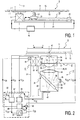
- Fig. 1 diagrammatically shows an optical player in accordance with the invention, which comprises a table 1 which is rotatable about an axis of rotation 3 and drivable by an electric motor 5 which is secured on a frame 7.
- an optically scannable information carrier 9 such as a CD
- the optical player further comprises an optical scanning device 17 in accordance with the invention for optically scanning the information track of the information carrier 9.
- the scanning device 17 can be displaced with respect to the axis of rotation 3 substantially in two opposite radial directions X and X' by means of a displacement device 19 of the optical player.
- the scanning device 17 is secured to a slide 21 of the displacement device 19 which is further provided with a straight guide 23, which extends parallel to the X-direction and is provided on the frame 7, over which guide the slide 21 is displaceably guided, and with an electric motor 25 by means of which the slide 21 can be displaced over the guide.
- an electrical control member 26 of the optical player which is only diagrammatically shown in Fig.
- the motors 5 and 25 controls the motors 5 and 25 in such a manner that the information carrier 9 is made to rotate about the axis of rotation 3 and, simultaneously, the scanning device 17 is displaced parallel to the X-direction, in such a manner that the spiral-shaped information track present on the information carrier 9 is scanned by the scanning device 17.
- the information present on the information track can be read by the scanning device 17, or information can be written on the information track by the scanning device 17.
- the optical scanning device 17 in accordance with the invention used in the optical player in accordance with the invention is diagrammatically shown in Fig. 2 .
- the scanning device 17 is provided with a radiation source 27, such as a semiconductor laser, with an optical axis 29.
- the scanning device 17 further comprises a radiation beam splitter 31 which comprises a transparent plate 33 which is arranged at an angle of 45° with respect to the optical axis 29 of the radiation source 27 and which includes a mirror surface 35 facing the radiation source 27.
- the scanning device 17 further comprises an optical lens system 37 with an optical axis 39 and a collimator lens 41 arranged between the radiation beam splitter 31 and the lens system 37.
- the optical axis 39 of the lens system 37 and the optical axis 29 of the radiation source 27 include an angle of 90°.
- the scanning device 17 further comprises an optical detector 43 which is of a customary type which is known per se, and which, with respect to the lens system 37, is arranged behind the radiation beam splitter 31.
- the radiation source 27 generates a radiation beam 45 which is reflected by the mirror surface 35 of the radiation beam splitter 31 and focused by the lens system 37 into a scanning spot 47 on the information layer 15 of the information carrier 9.
- the radiation beam 45 is reflected by the information layer 15 so as to form a reflected radiation beam 49 which is focused on the optical detector 43 via the lens system 37, the collimator lens 41 and the radiation beam splitter 31.
- the radiation source 27 To read the information present on the information carrier 9, the radiation source 27 generates a continuous radiation beam 45, the optical detector 43 supplying a detection signal which corresponds to a series of elementary information characteristics on the information track of the information carrier 9, which elementary information characteristics are successively present in the scanning spot 47. To write information on the information carrier 9, the radiation source 27 generates a radiation beam 45 which corresponds with information to be written, while in the scanning spot 47 there are generated a series of successive elementary information characteristics on the information track of the information carrier 9.
- the scanning device 17 comprises a first actuator 51 having a first part 52 and a second part 53.
- the lens system 37 can be displaced over relatively small distances in a direction parallel to the optical axis 39, while the lens system 37 can be displaced over relatively small distances in a direction parallel to the X-direction by means of the second part 53 of the first actuator 51.
- the scanning spot 47 is focused on the information layer 15 of the information carrier 9 with a desired degree of accuracy.
- the scanning spot 47 is maintained, with a desired accuracy, on the information track to be followed.
- the first part 52 and the second part 53 of the first actuator 51 are controlled, in a manner which will be described in more detail hereinafter, by said control member 26.
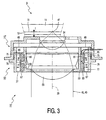
- the optical lens system 37 used in the optical scanning device 17 is shown in detail in Fig. 3 , and comprises a first lens 54 and a second lens 55.
- the second lens 55 is an objective lens and forms a relatively large main lens of the lens system 37.
- the first lens 54 is a so-called solid-immersion lens which is arranged between the main lens 55 and the information carrier 9 to be scanned, and forms a relatively small auxiliary lens of the lens system 37.
- the lens system 37 has a relatively large numerical aperture, so that the scanning spot 47 on the information layer 15 of the information carrier 9 is relatively small.
- the scanning device 17 can suitably be used for scanning optical information carriers having relatively small elementary information characteristics, i.e.
- the auxiliary lens 54 is secured in a fixed position to a housing 57 of the lens system 37, said housing 57 being secured to the first actuator 51 and hence being displaceable by means of the first actuator 51.
- the main lens 55 is secured to a substantially ring-shaped holder 59 which, viewed in a direction parallel to the optical axis 39, is elastically suspended in the housing 57 by means of two ring-shaped diaphragms 65, 67 which, viewed in a direction parallel to the optical axis 39, are arranged at a distance from each other and extend transversely to the optical axis 39.
- the diaphragms 65, 67 are elastically deformable and, viewed in directions perpendicular to the optical axis 39, they are substantially non-deformable, so that, viewed in directions perpendicular to the optical axis 39, the diaphragms 65, 67 provide a very rigid bearing of the main lens 55 with respect to the housing 57, while, viewed in a direction parallel to the optical axis 39, the main lens 55 can be displaced relatively to the housing 57, thereby elastically deforming the diaphragms 65, 67.
- the lens system 37 comprises a second actuator 63 by means of which the main lens 55 can be displaced with respect to the housing 57 and the auxiliary lens 54 in a direction parallel to the optical axis 39.
- a spherical aberration of the radiation beam 45 in the transparent protective layer 13 of the information carrier 9 is corrected.
- Such a spherical aberration can be mainly attributed to fluctuations or deviations in the thickness t of the protective layer 13.
- the second actuator 63 is also controlled by said control member 26 in a manner to be described in more detail hereinafter.
- the second actuator 63 is arranged between the two diaphragms 65, 67 and is a so-called Lorentz force actuator.
- the second actuator 63 comprises two ring-shaped permanent magnets 75, 77 which, viewed in a direction parallel to the optical axis 39, are arranged next to each other and are secured to a substantially ring-shaped closing yoke 79 which is made of a magnetizable material and forms a separate part of the housing 57.
- the second actuator 63 further comprises two ring-shaped electrical coils 81, 83 which are secured to the holder 59 of the main lens 55.
- the coils 81, 83 are also arranged in a side-by-side relationship, the coil 81 being arranged opposite the magnet 75 and the coil 83 being arranged opposite the magnet 77, and a ring-shaped air gap 85 being present between the magnets 75, 77 and the coils 81, 83.
- the magnets 75, 77 are magnetized in opposite radial directions R and R' with respect to the optical axis 39, while, in operation, an electric current in the coil 81 and an electric current in the coil 83 have mutually opposite current directions.
- the electromagnetic forces which, in operation, are exerted on the coils 81 and 83 by an interaction between a magnetic field of the magnets 75, 77 and the electric current in the coils 81, 83, are directed parallel to the optical axis 39 and substantially in the same direction with respect to each other.
- the control member 26 comprises a first control unit 87 which, in operation, controls the first part 52 of the first actuator 51 by means of a control signal u C1 .
- the first control unit 87 receives a focus-error signal u FE , which corresponds to a measured focusing error of the scanning spot 47 on the information layer 15 of the information carrier 9, and which is supplied by the optical detector 43. Such focusing errors lead to read and write errors of the scanning device 17 and hence are undesirable.
- the first control unit 87 determines the first control signal u C1 in such a manner that the measured focusing error remains within predetermined limits.
- the control member 26 further comprises a second control unit 89 which, in operation, controls the second actuator 63 by means of a second control signal u C2 .
- the second control unit 89 receives a measuring signal u SA , which corresponds to a measured spherical aberration of the radiation beam 45 in the protective layer 13 of the information carrier 9. Such a spherical aberration also leads to read and write errors of the scanning device 17 and hence is also undesirable.
- the measuring signal u SA is supplied by a further optical detector 91 of the scanning device 17, by means of which the thickness t of the protective layer 13 can be measured.
- the measuring signal u SA may alternatively be supplied by another type of optical detector.
- the second control unit 89 determines the second control signal u C2 in such a manner that the measured spherical aberration of the radiation beam 45 in the protective layer 13 of the information carrier 9 remains within predetermined limits.
- the second actuator 63 in accordance with the invention is also controlled by the first control unit 87 by means of a third control signal u C3 , as will be explained in greater detail hereinafter.
- the control member 26 further comprises a third control unit 93 which, in operation, controls the second part 53 of the first actuator 51 by means of a fourth control signal u C4 .
- the third control unit 93 receives a tracking error signal u TE , which corresponds to a measured tracking error of the scanning spot 47 on the information track of the information carrier 9, and is also supplied by the optical detector 43. Such tracking errors also lead to read and write errors of the scanning device 17 and hence are also undesirable. In operation, the third control unit 93 determines the fourth control signal u C4 in such a manner that the measured tracking error remains within predetermined limits.
- the second actuator 63 is controlled by the first control unit 87 for the reason, and in the manner, described hereinbelow.
- the main lens 55 and the ring-shaped diaphragms 65, 67 by means of which the main lens 55 is elastically suspended in the housing 57 of the lens system 37, viewed in a direction parallel to the optical axis 39, form a mass spring system within the lens system 37, having a natural frequency which is determined by a mechanical rigidity of the diaphragms 65, 67 and a mass of the main lens 55 and the holder 59.
- the diaphragms 65, 67 have a limited rigidity, so that said mass spring system has a limited natural frequency.
- the natural frequency of said mass spring system is approximately 250 Hz.
- the focusing errors to be corrected by means of the first part 52 of the first actuator 51 have relatively low-frequency components, relatively high-frequency components, and components with a frequency in a medium-frequency range which comprises the natural frequency of said mass spring system.
- the third control signal u C3 in accordance with the invention is proportional to the first control signal u C1 .
- the second actuator 63 is a Lorentz force actuator
- the second actuator 63 exerts a force component F C3 on the main lens 55, which force component is determined by the third control signal u C3 and directed parallel to the optical axis 39, said force component being proportional to the third control signal u C3 and hence also to the first control signal u C1 .
- the first part 52 of the first actuator 51 also is a force actuator which exerts a force F C1 on the entire lens system 37 in a direction parallel to the optical axis 39, which force is proportional to the first control signal u C1 .
- the force component F C3 of the second actuator 63 is proportional to the force F C1 of the first part 52 of the first actuator 51.
- the main lens 55 is displaced by means of the second actuator 63, as a result of the third control signal u C3 , in a direction parallel to the optical axis 39 at an acceleration which corresponds to an acceleration with which the entire lens system 37 is displaced by means of the first part 52 of the first actuator 51 in a direction parallel to the optical axis 39 as a result to of the first control signal u C1 .
- the main lens 55 which is elastically suspended in the housing 57, follows the displacements of the housing 57 of the lens system 37, which are directed parallel to the optical axis 39, so that said substantially undamped resonating displacements of the main lens 55 with respect to the housing 57 and the auxiliary lens 54 are precluded as much as possible.
- Said suitable ratio between the first control signal u C1 and the third control signal u C3 is determined by a ratio between the mass of the main lens 55 and the mass of the entire lens 37 and by the properties of the first part 52 of the first actuator 51 and the second actuator 63.
- the control member 26 includes an adder 95 which adds a control signal u' C3 , which will be described in greater detail hereinafter and which is derived from the third control signal u C3 , to the second control signal u C2 and supplies a sum u C2 +u' C3 of said control signals to the second actuator 63.
- the first control unit 87 is connected to the second actuator 63 via a pass filter 97 which is arranged between the first control unit 87 and the adder 95.
- Said pass filter 97 comprises both a low-pass filter, which filters out relatively high-frequency components in the control signal u C3 , i.e. components with a frequency which is an order higher than the natural frequency of said mass spring system, and a high-pass filter, which filters out relatively low-frequency components, particularly direct current components, in the control signal u C3 .
- the above-mentioned control signal u' C3 is a control signal which is formed, as described above, by filtering the third control signal u C3 .
- the main lens 55 substantially does not follow relatively high-frequency displacements of the lens system 37, for example displacements with a frequency above approximately 2500 Hz.
- the main lens 55 even is substantially not displaced relatively to the fixed part of the scanning device 17 in the case of such high-frequency displacements of the lens system 37.
- the main lens 55 has substantial mass, the mass to be displaced by the first part 52 of the first actuator 51 is substantially limited in the case of such high-frequency displacements of the lens system 37.
- the forces to be generated by the first part 52 of the first actuator 51 are proportional to the mass to be displaced and to the square of the frequency of the displacements to be generated, the forces to be generated by the first part 52 of the first actuator 51 for correcting high-frequency focusing errors are limited substantially. Consequently, the high-frequency focusing errors are corrected substantially exclusively by means of displacements of the auxiliary lens 54. In practice, this proved to be possible in that such high-frequency focusing errors customarily have relatively small amplitudes.
- the pass filter 97 is provided with said high-pass filter, direct current components are filtered from the third control signal u C3 .
- a spherical aberration of the radiation beam 45 in the protective layer 13 of the information carrier 9 can be sufficiently corrected in most cases by displacing the main lens 55 once-only with respect to the auxiliary lens 54, which displacement is determined by an average thickness of the protective layer 13. Consequently, in most cases the second control signal u C2 is a direct current signal.
- said high-pass filter filters direct current components from the third control signal u C3 , it is precluded that a correction of said spherical aberration by means of the second control signal u C2 is influenced or disturbed by direct current components or low-frequency components of the third control signal u C3 .
- the invention also relates to optical players by means of which only information present on an information track of an information carrier can be read, and to optical players by means of which only information can be written on an information track of an information carrier.
- the main lens 55 is elastically suspended in the housing 57 of the lens system 37, viewed in a direction parallel to the optical axis 39, while the auxiliary lens 54 is secured in a fixed position in the housing 57.
- the invention also includes scanning devices wherein, as in the case of the scanning device described in US patent 5,712,842 , the main lens is secured in a fixed position in the housing of the lens system, and the auxiliary lens is elastically suspended in the housing, viewed in a direction parallel to the optical axis of the lens system.
- a ratio between the first control signal u C1 and the third control signal u C3 is determined such that the accelerations of, respectively, the main lens 55 and the entire lens system 37, generated by means of the second actuator 63 and the first part 52 of the first actuator 51, are substantially equal. It is noted that, in many cases, undesirable resonating movements of the main lens 55 in the housing 57 of the lens system 37 can also be sufficiently precluded if the generated accelerations of the main lens 55 and the lens system 37 are not entirely equal to each other. For example, such resonating movements can often be sufficiently precluded if the generated acceleration of the main lens 55 amounts to approximately 70% or less of the generated acceleration of the entire lens system 37.
- the second actuator 63 and the first part 52 of the first actuator 51 preferably are force actuators.
- a suitable ratio between the first control signal u C1 and the third control signal u C3 can be reliably determined and a reliable operation of the scanning device 17 is obtained.
- the invention also includes scanning devices wherein the first actuator and the second actuator are of a different type, such as an actuator or motor wherein the control signal determines the displacement generated by the actuator or motor. In this case, however, a suitable ratio between the first control signal and the third control signal can be determined in a less reliable manner.
Landscapes
- Physics & Mathematics (AREA)
- Optics & Photonics (AREA)
- Optical Recording Or Reproduction (AREA)
- Optical Head (AREA)
Abstract
Claims (5)
- Dispositif de balayage optique pour balayer une piste d'information d'un support d'information susceptible de balayage optique (9), lequel dispositif de balayage (17) est pourvu d'une source de rayonnement (27), d'un système optique de lentilles (37) avec un axe optique (39) pour focaliser un faisceau de rayonnement (45) qui est fourni, en fonctionnement, par la source de rayonnement dans un spot de rayonnement (47) sur le support d'information, d'un premier actionneur (51) pour déplacer le système de lentilles dans une direction qui est parallèle à l'axe optique et d'une première unité de commande (87) pour commander le premier actionneur au moyen d'un premier signal de commande (UC1), ledit système de lentilles étant pourvu d'un boîtier (57), d'une première lentille (54) qui est fixée dans le boîtier (57) dans une position fixe, d'une deuxième lentille (55) qui est suspendue d'une manière élastique, vu dans une direction étant parallèle à l'axe optique, dans le boîtier et d'un deuxième actionneur (63) au moyen duquel la deuxième lentille peut être déplacée par rapport à la première lentille dans une direction étant parallèle à l'axe optique alors que l'unité de balayage est pourvue d'une deuxième unité de commande (89) pour commander le deuxième actionneur au moyen d'un deuxième signal de commande (UC2), caractérisé en ce que, en fonctionnement, la première unité de commande (87) commande également le deuxième actionneur (63) au moyen d'un troisième signal de commande (UC3) qui est proportionnel au premier signal de commande ((UC1).
- Dispositif de balayage optique selon la revendication 1, caractérisé en ce que la deuxième lentille est une lentille principale du système de lentilles alors que la première lentille est une lentille auxiliaire du système de lentilles qui est agencé entre la deuxième lentille et le support d'information à balayer.
- Dispositif de balayage optique selon la revendication 1 ou 2, caractérisé en ce que la première unité de commande est reliée au deuxième actionneur par le biais d'un filtre passe-bas.
- Dispositif de balayage optique selon la revendication 1, 2 ou 3, caractérisé en ce que la première unité de commande est reliée au deuxième actionneur par le biais, successivement, d'un filtre passe-haut et d'un additionneur pour additionner le deuxième signal de commande et le troisième signal de commande.
- Lecteur optique comprenant un plateau qui peut être tourné autour d'un axe de rotation, un dispositif de balayage optique pour balayer une piste d'information d'un support d'information susceptible de balayage optique qui peut être placé sur ledit plateau et un dispositif de déplacement au moyen duquel le dispositif de balayage peut être déplacé principalement dans une direction radiale par rapport à l'axe de rotation, caractérisé en ce que le dispositif de balayage optique est un dispositif de balayage optique selon la revendication 1, 2, 3 ou 4.
Priority Applications (1)
| Application Number | Priority Date | Filing Date | Title |
|---|---|---|---|
| EP00901100A EP1084492B1 (fr) | 1999-02-03 | 2000-01-13 | Dispositif de balayage optique a actionneurs commandes en parallele |
Applications Claiming Priority (4)
| Application Number | Priority Date | Filing Date | Title |
|---|---|---|---|
| EP99200318 | 1999-02-03 | ||
| EP99200318 | 1999-02-03 | ||
| PCT/EP2000/000228 WO2000046800A2 (fr) | 1999-02-03 | 2000-01-13 | Dispositif de balayage optique a actionneurs commandes en parallele |
| EP00901100A EP1084492B1 (fr) | 1999-02-03 | 2000-01-13 | Dispositif de balayage optique a actionneurs commandes en parallele |
Publications (2)
| Publication Number | Publication Date |
|---|---|
| EP1084492A2 EP1084492A2 (fr) | 2001-03-21 |
| EP1084492B1 true EP1084492B1 (fr) | 2008-07-23 |
Family
ID=8239862
Family Applications (1)
| Application Number | Title | Priority Date | Filing Date |
|---|---|---|---|
| EP00901100A Expired - Lifetime EP1084492B1 (fr) | 1999-02-03 | 2000-01-13 | Dispositif de balayage optique a actionneurs commandes en parallele |
Country Status (8)
| Country | Link |
|---|---|
| US (1) | US6594205B1 (fr) |
| EP (1) | EP1084492B1 (fr) |
| JP (1) | JP4090695B2 (fr) |
| KR (1) | KR100695460B1 (fr) |
| CN (1) | CN1146879C (fr) |
| DE (1) | DE60039562D1 (fr) |
| MY (1) | MY123486A (fr) |
| WO (1) | WO2000046800A2 (fr) |
Families Citing this family (9)
| Publication number | Priority date | Publication date | Assignee | Title |
|---|---|---|---|---|
| JP3956547B2 (ja) * | 1999-09-07 | 2007-08-08 | ソニー株式会社 | 光記録装置、光記録及び/又は再生方法 |
| JP2002279680A (ja) * | 2001-03-21 | 2002-09-27 | Konica Corp | 光ピックアップ装置、光ピックアップ装置の集光光学系及び光情報記録再生方法、 |
| ATE364225T1 (de) * | 2002-04-09 | 2007-06-15 | Koninkl Philips Electronics Nv | Zusammengesetzte objektivlinse mit umlenkungsspiegel |
| US20050094258A1 (en) * | 2003-10-31 | 2005-05-05 | Hamamatsu Photonics K.K. | Solid immersion lens moving device and microscope using the same |
| JP4497970B2 (ja) * | 2004-03-22 | 2010-07-07 | キヤノン株式会社 | レンズ装置 |
| JP2009509279A (ja) * | 2005-09-16 | 2009-03-05 | コーニンクレッカ フィリップス エレクトロニクス エヌ ヴィ | 光学走査デバイス用のアクチュエーター |
| JP2007172786A (ja) * | 2005-12-26 | 2007-07-05 | Pentax Corp | 光情報処理装置 |
| JP2007293210A (ja) * | 2006-04-27 | 2007-11-08 | Olympus Corp | イメージング装置 |
| JP5006602B2 (ja) * | 2006-08-31 | 2012-08-22 | キヤノン株式会社 | 撮像装置 |
Family Cites Families (8)
| Publication number | Priority date | Publication date | Assignee | Title |
|---|---|---|---|---|
| US4327434A (en) * | 1980-01-28 | 1982-04-27 | Rca Corporation | Video disc stylus position sensor system |
| JP2930447B2 (ja) * | 1991-05-15 | 1999-08-03 | キヤノン株式会社 | 情報処理装置 |
| JPH0511854A (ja) * | 1991-07-04 | 1993-01-22 | Mitsubishi Electric Corp | 2段アクチユエータ制御装置 |
| JPH07122009A (ja) * | 1993-10-22 | 1995-05-12 | Sony Corp | トラッキングトラバース制御回路 |
| US5551360A (en) * | 1994-02-03 | 1996-09-03 | Brother Kogyo Kabushiki Kaisha | Vibration control device for sewing machine |
| JP3567515B2 (ja) | 1995-02-15 | 2004-09-22 | ソニー株式会社 | 光学ピックアップ装置 |
| JPH1089403A (ja) * | 1996-09-10 | 1998-04-07 | Nikon Corp | 防振装置 |
| JP2002505789A (ja) * | 1998-04-17 | 2002-02-19 | コーニンクレッカ フィリップス エレクトロニクス エヌ ヴィ | 主レンズおよび補助レンズを有する光学走査装置 |
-
2000
- 2000-01-13 EP EP00901100A patent/EP1084492B1/fr not_active Expired - Lifetime
- 2000-01-13 CN CNB008004927A patent/CN1146879C/zh not_active Expired - Fee Related
- 2000-01-13 JP JP2000597799A patent/JP4090695B2/ja not_active Expired - Fee Related
- 2000-01-13 KR KR1020007010965A patent/KR100695460B1/ko not_active Expired - Fee Related
- 2000-01-13 WO PCT/EP2000/000228 patent/WO2000046800A2/fr not_active Ceased
- 2000-01-13 DE DE60039562T patent/DE60039562D1/de not_active Expired - Lifetime
- 2000-01-31 MY MYPI20000344A patent/MY123486A/en unknown
- 2000-02-03 US US09/498,259 patent/US6594205B1/en not_active Expired - Lifetime
Also Published As
| Publication number | Publication date |
|---|---|
| JP2002536775A (ja) | 2002-10-29 |
| WO2000046800A3 (fr) | 2000-12-28 |
| MY123486A (en) | 2006-05-31 |
| WO2000046800A2 (fr) | 2000-08-10 |
| CN1306660A (zh) | 2001-08-01 |
| CN1146879C (zh) | 2004-04-21 |
| US6594205B1 (en) | 2003-07-15 |
| EP1084492A2 (fr) | 2001-03-21 |
| KR20010042394A (ko) | 2001-05-25 |
| JP4090695B2 (ja) | 2008-05-28 |
| DE60039562D1 (de) | 2008-09-04 |
| KR100695460B1 (ko) | 2007-03-15 |
Similar Documents
| Publication | Publication Date | Title |
|---|---|---|
| US4561081A (en) | Opto-electronic apparatus for inscribing and/or reading recording tracks by means of a radiation beam | |
| EP0310156B1 (fr) | Lecteur de disques optiques | |
| EP0063934A2 (fr) | Dispositifs optiques pour commander un faisceau lumineux | |
| EP1084492B1 (fr) | Dispositif de balayage optique a actionneurs commandes en parallele | |
| EP0990232B1 (fr) | Dispositif de numerisation optique comprenant un systeme de lentilles et muni d'un actionneur compact | |
| KR950013703B1 (ko) | 광 픽업의 대물렌즈 구동장치 | |
| EP0990187B1 (fr) | Procede de fabrication de systeme de lentilles a deux lentilles | |
| US6310840B1 (en) | Optical scanning device comprising a main lens and an auxiliary lens | |
| JPH01273235A (ja) | 対物レンズ支持・配置システム | |
| EP1175671B1 (fr) | Dispositif de balayage optique comprenant un actionneur pour une lentille de collimateur mobile | |
| EP1342236B1 (fr) | Dispositif optique de balayage a objectif pivotant | |
| JPS624909Y2 (fr) | ||
| EP1108256B1 (fr) | Dispositif de balayage optique comprenant un systeme de lentille a inclinaison reglable | |
| KR20010051659A (ko) | 대물렌즈 구동장치 | |
| KR100819938B1 (ko) | 광학 주사장치 및 그 주사장치를 구비한 광학 재생장치 | |
| JPH01311426A (ja) | 対物レンズ駆動装置 | |
| MXPA01010789A (en) | Optical scanning device comprising an actuator for a displaceable collimator lens | |
| JPH04319554A (ja) | 光磁気記録再生装置 |
Legal Events
| Date | Code | Title | Description |
|---|---|---|---|
| PUAI | Public reference made under article 153(3) epc to a published international application that has entered the european phase |
Free format text: ORIGINAL CODE: 0009012 |
|
| AK | Designated contracting states |
Kind code of ref document: A2 Designated state(s): AT BE CH CY DE DK ES FI FR GB GR IE IT LI LU MC NL PT SE |
|
| 17P | Request for examination filed |
Effective date: 20010628 |
|
| RBV | Designated contracting states (corrected) |
Designated state(s): BE DE FR GB IT |
|
| GRAP | Despatch of communication of intention to grant a patent |
Free format text: ORIGINAL CODE: EPIDOSNIGR1 |
|
| GRAS | Grant fee paid |
Free format text: ORIGINAL CODE: EPIDOSNIGR3 |
|
| GRAA | (expected) grant |
Free format text: ORIGINAL CODE: 0009210 |
|
| AK | Designated contracting states |
Kind code of ref document: B1 Designated state(s): BE DE FR GB IT |
|
| REG | Reference to a national code |
Ref country code: GB Ref legal event code: FG4D |
|
| REF | Corresponds to: |
Ref document number: 60039562 Country of ref document: DE Date of ref document: 20080904 Kind code of ref document: P |
|
| PG25 | Lapsed in a contracting state [announced via postgrant information from national office to epo] |
Ref country code: BE Free format text: LAPSE BECAUSE OF FAILURE TO SUBMIT A TRANSLATION OF THE DESCRIPTION OR TO PAY THE FEE WITHIN THE PRESCRIBED TIME-LIMIT Effective date: 20080723 |
|
| PLBE | No opposition filed within time limit |
Free format text: ORIGINAL CODE: 0009261 |
|
| STAA | Information on the status of an ep patent application or granted ep patent |
Free format text: STATUS: NO OPPOSITION FILED WITHIN TIME LIMIT |
|
| 26N | No opposition filed |
Effective date: 20090424 |
|
| PG25 | Lapsed in a contracting state [announced via postgrant information from national office to epo] |
Ref country code: IT Free format text: LAPSE BECAUSE OF FAILURE TO SUBMIT A TRANSLATION OF THE DESCRIPTION OR TO PAY THE FEE WITHIN THE PRESCRIBED TIME-LIMIT Effective date: 20080723 |
|
| PGFP | Annual fee paid to national office [announced via postgrant information from national office to epo] |
Ref country code: GB Payment date: 20110131 Year of fee payment: 12 |
|
| GBPC | Gb: european patent ceased through non-payment of renewal fee |
Effective date: 20120113 |
|
| PG25 | Lapsed in a contracting state [announced via postgrant information from national office to epo] |
Ref country code: GB Free format text: LAPSE BECAUSE OF NON-PAYMENT OF DUE FEES Effective date: 20120113 |
|
| REG | Reference to a national code |
Ref country code: DE Ref legal event code: R082 Ref document number: 60039562 Country of ref document: DE Representative=s name: MEISSNER, BOLTE & PARTNER GBR, DE |
|
| REG | Reference to a national code |
Ref country code: DE Ref legal event code: R081 Ref document number: 60039562 Country of ref document: DE Owner name: KONINKLIJKE PHILIPS N.V., NL Free format text: FORMER OWNER: KONINKLIJKE PHILIPS ELECTRONICS N.V., EINDHOVEN, NL Effective date: 20140328 Ref country code: DE Ref legal event code: R082 Ref document number: 60039562 Country of ref document: DE Representative=s name: MEISSNER, BOLTE & PARTNER GBR, DE Effective date: 20140328 Ref country code: DE Ref legal event code: R082 Ref document number: 60039562 Country of ref document: DE Representative=s name: MEISSNER BOLTE PATENTANWAELTE RECHTSANWAELTE P, DE Effective date: 20140328 |
|
| REG | Reference to a national code |
Ref country code: FR Ref legal event code: CA Effective date: 20141126 Ref country code: FR Ref legal event code: CD Owner name: KONINKLIJKE PHILIPS N.V., NL Effective date: 20141126 |
|
| PGFP | Annual fee paid to national office [announced via postgrant information from national office to epo] |
Ref country code: DE Payment date: 20150331 Year of fee payment: 16 |
|
| REG | Reference to a national code |
Ref country code: FR Ref legal event code: PLFP Year of fee payment: 17 |
|
| PGFP | Annual fee paid to national office [announced via postgrant information from national office to epo] |
Ref country code: FR Payment date: 20160129 Year of fee payment: 17 |
|
| REG | Reference to a national code |
Ref country code: DE Ref legal event code: R119 Ref document number: 60039562 Country of ref document: DE |
|
| PG25 | Lapsed in a contracting state [announced via postgrant information from national office to epo] |
Ref country code: DE Free format text: LAPSE BECAUSE OF NON-PAYMENT OF DUE FEES Effective date: 20160802 |
|
| REG | Reference to a national code |
Ref country code: FR Ref legal event code: ST Effective date: 20170929 |
|
| PG25 | Lapsed in a contracting state [announced via postgrant information from national office to epo] |
Ref country code: FR Free format text: LAPSE BECAUSE OF NON-PAYMENT OF DUE FEES Effective date: 20170131 |