EP1084535B1 - Empfänger für cdma-system - Google Patents
Empfänger für cdma-system Download PDFInfo
- Publication number
- EP1084535B1 EP1084535B1 EP99923648A EP99923648A EP1084535B1 EP 1084535 B1 EP1084535 B1 EP 1084535B1 EP 99923648 A EP99923648 A EP 99923648A EP 99923648 A EP99923648 A EP 99923648A EP 1084535 B1 EP1084535 B1 EP 1084535B1
- Authority
- EP
- European Patent Office
- Prior art keywords
- signal
- receiver
- sequences
- filter
- sequence
- Prior art date
- Legal status (The legal status is an assumption and is not a legal conclusion. Google has not performed a legal analysis and makes no representation as to the accuracy of the status listed.)
- Expired - Lifetime
Links
- 238000001228 spectrum Methods 0.000 claims description 11
- 238000011084 recovery Methods 0.000 claims description 6
- 230000001360 synchronised effect Effects 0.000 description 10
- 230000005540 biological transmission Effects 0.000 description 7
- 238000000034 method Methods 0.000 description 7
- 238000007792 addition Methods 0.000 description 3
- 230000003595 spectral effect Effects 0.000 description 3
- 230000003111 delayed effect Effects 0.000 description 2
- 238000009434 installation Methods 0.000 description 2
- 230000033764 rhythmic process Effects 0.000 description 2
- 238000005070 sampling Methods 0.000 description 2
- 230000002089 crippling effect Effects 0.000 description 1
- 238000001514 detection method Methods 0.000 description 1
- 238000005562 fading Methods 0.000 description 1
- 230000036039 immunity Effects 0.000 description 1
- 244000045947 parasite Species 0.000 description 1
- 230000003071 parasitic effect Effects 0.000 description 1
- 230000000306 recurrent effect Effects 0.000 description 1
- 238000000926 separation method Methods 0.000 description 1
- 230000002123 temporal effect Effects 0.000 description 1
- 230000002747 voluntary effect Effects 0.000 description 1
Images


Classifications
-
- H—ELECTRICITY
- H04—ELECTRIC COMMUNICATION TECHNIQUE
- H04B—TRANSMISSION
- H04B1/00—Details of transmission systems, not covered by a single one of groups H04B3/00 - H04B13/00; Details of transmission systems not characterised by the medium used for transmission
- H04B1/69—Spread spectrum techniques
- H04B1/707—Spread spectrum techniques using direct sequence modulation
- H04B1/7073—Synchronisation aspects
- H04B1/7075—Synchronisation aspects with code phase acquisition
- H04B1/708—Parallel implementation
-
- H—ELECTRICITY
- H04—ELECTRIC COMMUNICATION TECHNIQUE
- H04B—TRANSMISSION
- H04B1/00—Details of transmission systems, not covered by a single one of groups H04B3/00 - H04B13/00; Details of transmission systems not characterised by the medium used for transmission
- H04B1/69—Spread spectrum techniques
- H04B1/707—Spread spectrum techniques using direct sequence modulation
- H04B1/709—Correlator structure
- H04B1/7095—Sliding correlator type
-
- H—ELECTRICITY
- H04—ELECTRIC COMMUNICATION TECHNIQUE
- H04J—MULTIPLEX COMMUNICATION
- H04J13/00—Code division multiplex systems
- H04J13/0007—Code type
- H04J13/0022—PN, e.g. Kronecker
-
- H—ELECTRICITY
- H04—ELECTRIC COMMUNICATION TECHNIQUE
- H04B—TRANSMISSION
- H04B2201/00—Indexing scheme relating to details of transmission systems not covered by a single group of H04B3/00 - H04B13/00
- H04B2201/69—Orthogonal indexing scheme relating to spread spectrum techniques in general
- H04B2201/707—Orthogonal indexing scheme relating to spread spectrum techniques in general relating to direct sequence modulation
- H04B2201/70707—Efficiency-related aspects
Definitions
- the present invention relates to a receiver for CDMA system, that is to say for multiple access systems with code distribution, technique known in English under the abbreviation CDMA (for "Code Division Multiple Access”). More generally, this technique is part of digital spread spectrum direct sequence transmission (abbreviated DSSS for "Direct Sequence Spread Spectrum”).
- CDMA Code Division Multiple Access
- DSSS Digital Spread spectrum direct sequence transmission
- the invention finds applications in radiocommunication systems with mobiles, in wireless local area networks (WLAN: “Wireless Local Area Network”), in local loops of wireless subscribers (WLL “Wireless Local Loop”), in cable TV, etc ...
- Spectrum spreading by direct sequence consists in modulating each symbol of the digital signal by a pseudo-random binary sequence. Such a sequence is composed of N pulses or "chips" whose duration Tc is equal to Ts / N.
- the modulated signal has a spectrum which spans a range N times wider than that of the original signal.
- demodulation consists of correlating the signal with the sequence used on transmission, which makes it possible to find the information linked to the starting symbol.
- the CDMA technique consists in the simultaneous emission, in the same band, of several spread signals using pseudo-random sequences of different spreading.
- the sequences are chosen so that the intercorrelations remain weak. If the different transmitters do not have a common time reference, the system is said to be asynchronous since the beginnings of the symbols specific to each user reach the receiver at different times.
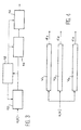
- FIG. 1 where the lines on the left represent the time for three different users 1, 2 and 3 and the arrows directed upwards represent the instants (the "tops") of start of transmission. symbols.
- the central part symbolically represents the routes to the same receiver.
- the right part shows the temporal position of the beginnings of the symbols received for each of the users, that is to say, ultimately, the phase differences of the symbols of the different users with respect to each other.
- the system is then said to be "synchronous". It is illustrated in Figure 2 with the same conventions.
- the sequences In an asynchronous CDMA system, the sequences have any relative phases at the level of the reception. Good signal separation requires so that the sequence ink intercorrelations are weak, whatever the relative phases between sequences. On the other hand, in synchronous ARMC, the sequences arriving with zero relative phases, the number of intercorrelations to be close to zero is much lower. This particularity gives the synchronous system a clear advantage over the variant asynchronous in terms of number of sequences (therefore users) that can coexist without disruption crippling mutual.
- the received signal can be written in the form: where the sign * marks a convolution product. This expression can still be written:
- FIG. 3 illustrates the principle of a spread spectrum signal receiver.
- the receiver shown comprises a first circuit 10, which can be a suitable filter or a sliding correlator, a circuit 12 for recovering a symbol clock signal, signal which allows the synchronization of the means of the receiver, possibly a processing circuit. 14 capable of carrying out various additional processing operations, such as for example a delayed multiplication, a channel estimation, etc., and finally a circuit 16 capable of making a decision on the value of the symbol transmitted.
- the receiver comprises as many channels as there are sequences, as shown in FIG. 4, with channels V 1 , V 2 , ..., V K where K is the number of users (or sequences). Each channel restores the symbols d 1 , d 2 , ... d k specific to its sequence, therefore to the user.
- a sliding correlator (FIG. 5) schematically comprises a pseudo-random sequence generator 20 and a multiplier 22 receiving the input signal r (t) and the sequence delivered by the generator 20, an adder 24, a circuit 26 connected to the output of the adder 24 and looped over it and realizing a delay.
- the output of the sliding correlator is connected to a subsampler 28.
- the circuits 20, 26, 28 are controlled by a symbol clock signal Hs.
- the adapted filter (FIG. 6) it is generally a digital filter 30 whose coefficients are adapted to the sequence used.
- This filter receives the input signal r (t) and delivers a filtered signal also applied to a subsampler 28.
- the latter is controlled by the symbol clock signal Hs, which fixes the rate of the symbols.
- Hs the symbol clock signal
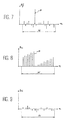
- FIGS. 7, 8 and 9 show the output Sf of the adapted digital filter of FIG. 6, as a function of the rank n of the samples;
- FIG. 8 the output Sc of the sliding correlator of FIG. 5 when the local replica of the transmitted sequence is aligned with the transmitted sequence; and
- FIG. 7 shows the output Sf of the adapted digital filter of FIG. 6, as a function of the rank n of the samples;
- FIG. 8 the output Sc of the sliding correlator of FIG. 5 when the local replica of the transmitted sequence is aligned with the transmitted sequence; and FIG.
- a suitable filter allows the recovery of the symbol clock, for example by a recurrent detection of the correlation peak over a window of N points (FIG. 7).
- the recovery of the symbol clock is also possible using a sliding correlator, but in a more complex way: it is necessary to modify step by step the phase of the local replica of the sequence until the output of the correlator sliding corresponds to a maximum of energy, therefore to a peak of correlation (case of figure 8). If these two structures make it possible to find the symbol clock, they do not do so with the same speed: the recovery operation of the symbol clock lasts at most N symbol periods, i.e. NTs with a correlator slippery, while it only requires a single symbol period Ts with a suitable filter.
- the advantage of the matched filter is therefore obvious in terms of speed of acquisition of the symbol clock signal. Its drawback is its operational complexity, since its implementation in the form of a digital filter with finite impulse response (working at the chip rate) requires N multiplications and N additions for each sample. Its structural complexity goes hand in hand with its operational complexity. The sliding correlator only performs a multiplication and an addition for each new sample. If it is relatively poorly suited to recovering the clock, it is however very advantageous in terms of operating complexity. Thus, whether we turn to suitable filters or to sliding correlators, we do not escape certain disadvantages. The purpose of the present invention is to remedy this.
- the invention proposes to combine the advantages of each of these structures (matched filter and sliding correlator) by using, in a multi-channel receiver, a matched filter in at least one channel, this in order to quickly and efficiently restore the symbol clock, and using sliding correlators in the other channels to take advantage of their low complexity, these correlators being controlled by the symbol clock signal produced by the matched filter.
- the receiver of the invention is therefore hybrid, in the sense that it comprises at least one channel using a suitable filter and other channels using sliding correlators. The complexity of the receiver is reduced by the use of correlators, without the efficiency of the restitution of the symbol clock signal being affected since this is ensured by a suitable digital filter.
- the adapted filter delivering a synchronization signal.
- the filter is adapted to a very specific sequence called pilot and not to the sequences serving to convey information. This suitable filter therefore only works when the pilot symbol is received.
- the sliding correlations then process the sequences conveying the information, while the adapted filter is ineffective. Synchronization is therefore obtained prior to demodulation.
- the adapted filter processes the symbols conveying the information and permanently maintains the clock signal necessary for the sliding correlators.
- the synchronism between the sequences is not perfect, it is possible to use several channels of the matched filter type, (instead of just one) so as to produce several symbol clock signals slightly offset from each other. to others.
- the invention therefore relates to a receiver for CDMA system, intended to receive signals corresponding to symbol sequences spectrum spread information pseudo-random binaries, this receptor comprising K routes of treatment and being characterized by the fact that at least one of these channels includes a suitable filter to one of the pseudo-random sequences used to spreading the spectrum of information symbols and a rhythm clock recovery circuit symbols, the other channels each comprising a sliding correlator working with one of the others sequences used to spread the spectrum of information symbols, each sliding correlator being controlled by a symbol clock signal, which is the clock signal produced by the channel using the suitable filter.
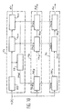
- FIG. 10 shows a receiver according to the invention.
- This receiver includes K channels, V 1 , V 2 , ..., V K of which one channel V 1 uses a suitable filter, while the K-1 other channels V 2 , ..., V K , use a sliding correlator .
- the channel V 1 comprises a digital filter 25 whose coefficients are adapted to the sequence No. 1 used on transmission, a circuit 12 for recovering the clock symbol Hs, an additional processing circuit 14 1 , suitable to perform, for example, a delayed multiplication, a channel estimation, etc ... and finally a decision circuit 16 1 restoring the information d 1 specific to the user having used this first sequence.
- the channel V 2 comprises a sliding correlator 30 2 , an additional processing circuit 14 2 and a decision circuit 16 2 delivering the restored information d 2 .
- V k which includes a correlator 30 K , a processing circuit 14 K and a decision circuit 16 K restoring the information d K.
- the correlators 30 2 , ..., 30 K need, as has been explained, a clock signal to be synchronized and this consists, in accordance with the invention, of the symbol clock signal Hs recovered in the first channel V 1 . This clock can also be applied to circuits 14 1 , 14 2 , ..., 14 K and 16 1 , 16 2 , ..., 16 K.
- Table 1 makes it possible to compare an architecture in accordance with the invention with a conventional architecture using either sliding correlators or suitable filters. The comparison is made in terms of operating complexity and duration of acquisition of the symbol clock (for K synchronous transmitters and sequences of length N).
- Receiver of the invention Classic receiver with suitable filters
- Classic receiver with sliding correlators Duration of acquisition of the symbol clock (in period Ts) 1 1 ⁇ N Operational complexity (in number of multiplications per sampling period) N + K-1 KN K Operating complexity (in number of additions per sampling period) N + K-1 KN K
Landscapes
- Engineering & Computer Science (AREA)
- Computer Networks & Wireless Communication (AREA)
- Signal Processing (AREA)
- Synchronisation In Digital Transmission Systems (AREA)
- Circuits Of Receivers In General (AREA)
Claims (1)
- Empfänger für CDMA-System, bestimmt für den Empfang von Signalen, die Folgen von durch Pseudozufallssequenzen gespreizten Symbolen sind, wobei dieser Empfänger, der K Verarbeitungskanäle (V1, V2, ..., VK) umfasst, dadurch gekennzeichnet ist, dass wenigstens einer dieser Kanäle V1 ein Filter (20), das an eine der Zufallssequenzen angepasst ist, die zur Spreizung des Spektrums der Informationssignale gedient haben, sowie eine Schaltung (12) zur Rückgewinnung eines Symbol-Taktsignals (Hs) umfasst, und die anderen Kanäle (V2, ..., VK) alle einen Gleitkorrelator (302, ..., 30K) umfassen, der mit einer der anderen Sequenzen arbeitet, die zur Spreizung des Spektrums der Informationssymbole gedient haben, wobei jeder Gleitkorrelator durch ein Symbol-Taktsignal gesteuert wird, das das durch den Kanal (V1) erzeugte Taktsignal (Hs) ist, der das angepasste Filter (20) benutzt.
Applications Claiming Priority (3)
| Application Number | Priority Date | Filing Date | Title |
|---|---|---|---|
| FR9806952A FR2779590B1 (fr) | 1998-06-03 | 1998-06-03 | Recepteur pour systeme amrc |
| FR9806952 | 1998-06-03 | ||
| PCT/FR1999/001287 WO1999063678A1 (fr) | 1998-06-03 | 1999-06-02 | Recepteur pour systeme amrc |
Publications (2)
| Publication Number | Publication Date |
|---|---|
| EP1084535A1 EP1084535A1 (de) | 2001-03-21 |
| EP1084535B1 true EP1084535B1 (de) | 2002-12-04 |
Family
ID=9526963
Family Applications (1)
| Application Number | Title | Priority Date | Filing Date |
|---|---|---|---|
| EP99923648A Expired - Lifetime EP1084535B1 (de) | 1998-06-03 | 1999-06-02 | Empfänger für cdma-system |
Country Status (6)
| Country | Link |
|---|---|
| US (2) | US6973120B1 (de) |
| EP (1) | EP1084535B1 (de) |
| DE (1) | DE69904321T2 (de) |
| ES (1) | ES2188169T3 (de) |
| FR (1) | FR2779590B1 (de) |
| WO (1) | WO1999063678A1 (de) |
Families Citing this family (1)
| Publication number | Priority date | Publication date | Assignee | Title |
|---|---|---|---|---|
| FR2779590B1 (fr) | 1998-06-03 | 2000-07-07 | Commissariat Energie Atomique | Recepteur pour systeme amrc |
Family Cites Families (10)
| Publication number | Priority date | Publication date | Assignee | Title |
|---|---|---|---|---|
| CH676179A5 (de) * | 1988-09-29 | 1990-12-14 | Ascom Zelcom Ag | |
| US6088590A (en) * | 1993-11-01 | 2000-07-11 | Omnipoint Corporation | Method and system for mobile controlled handoff and link maintenance in spread spectrum communication |
| US6005856A (en) * | 1993-11-01 | 1999-12-21 | Omnipoint Corporation | Communication protocol for spread spectrum wireless communication system |
| JP3192047B2 (ja) * | 1994-06-03 | 2001-07-23 | キヤノン株式会社 | スペクトラム拡散受信機 |
| ZA965340B (en) * | 1995-06-30 | 1997-01-27 | Interdigital Tech Corp | Code division multiple access (cdma) communication system |
| JPH09321667A (ja) * | 1996-05-29 | 1997-12-12 | Yozan:Kk | Cdma通信システム用受信機 |
| JP2746261B2 (ja) * | 1996-06-10 | 1998-05-06 | 日本電気株式会社 | Ds−cdma干渉キャンセル装置 |
| WO1998035458A1 (en) * | 1997-02-06 | 1998-08-13 | At & T Wireless Services, Inc. | Method of synchronizing a remote station with a base station in a discrete multitone spread spectrum communications system |
| FR2776869B1 (fr) * | 1998-03-24 | 2000-05-05 | Commissariat Energie Atomique | Recepteur amrc a suppression parallele d'interferences et a ponderation |
| FR2779590B1 (fr) * | 1998-06-03 | 2000-07-07 | Commissariat Energie Atomique | Recepteur pour systeme amrc |
-
1998
- 1998-06-03 FR FR9806952A patent/FR2779590B1/fr not_active Expired - Fee Related
-
1999
- 1999-06-02 US US09/701,391 patent/US6973120B1/en not_active Expired - Lifetime
- 1999-06-02 WO PCT/FR1999/001287 patent/WO1999063678A1/fr not_active Ceased
- 1999-06-02 DE DE69904321T patent/DE69904321T2/de not_active Expired - Lifetime
- 1999-06-02 ES ES99923648T patent/ES2188169T3/es not_active Expired - Lifetime
- 1999-06-02 EP EP99923648A patent/EP1084535B1/de not_active Expired - Lifetime
-
2005
- 2005-11-28 US US11/288,663 patent/US7801201B2/en not_active Expired - Fee Related
Also Published As
| Publication number | Publication date |
|---|---|
| WO1999063678A1 (fr) | 1999-12-09 |
| DE69904321D1 (de) | 2003-01-16 |
| DE69904321T2 (de) | 2003-09-04 |
| US7801201B2 (en) | 2010-09-21 |
| US20060078043A1 (en) | 2006-04-13 |
| FR2779590B1 (fr) | 2000-07-07 |
| US6973120B1 (en) | 2005-12-06 |
| EP1084535A1 (de) | 2001-03-21 |
| FR2779590A1 (fr) | 1999-12-10 |
| ES2188169T3 (es) | 2003-06-16 |
Similar Documents
| Publication | Publication Date | Title |
|---|---|---|
| EP1195924B1 (de) | Verfahren zur Synchronisation von Basisstationen | |
| CA2095257C (fr) | Procede et dispositif pour multiplexer des signaux de donnees | |
| CA2173779C (fr) | Recepteur de signal a spectre etale | |
| EP0608024A1 (de) | Übertragungssystem mit Taktrückgewinnung | |
| WO1999053644A1 (fr) | Signal de radiotelephonie cellulaire a canal supplementaire affecte au sens descendant, procede, systeme, mobile et station de base correspondants | |
| FR2813465A1 (fr) | Methode d'estimation conjointe de canal et de direction d'arrivee | |
| EP1293048A1 (de) | Verfahren und vorrichtung zur rauschunterdrückung in einem empfänger | |
| EP0917299B1 (de) | Digitale Direktsequenzspreizspektrumnachrichtenübertragung mit Störsignalgeneration | |
| EP0849889B1 (de) | Verfahren zum Mehrwegesignalempfang | |
| EP1084535B1 (de) | Empfänger für cdma-system | |
| EP1130861A1 (de) | Verfahren zur Schätzung eines Übertragungs- oder Telekommunikationskanals | |
| EP2161847A1 (de) | Datenübertragungsverfahren mit sich wiederholenden Spreizsequenzsätzen und entsprechender Sender und Empfänger | |
| EP0629059B1 (de) | Digitales Spreizspektrumübertragungssystem mit Niederfrequenz-Pseudozufallkodierung von Nutzinformation und Verfahren zur Spektrumsspreizung und Spektrumskomprimierung zur Verwendung in einem solchen System | |
| EP0820157A2 (de) | Verfahren zur digitalen Differenzialdemodulation | |
| EP0655845B1 (de) | Paketübertragungsanordnung mit gespreiztem Spektrum | |
| FR2770060A1 (fr) | Recepteur differentiel a etalement de spectre par sequence directe avec moyens mixtes de formation d'un signal d'interferences | |
| EP1244243A1 (de) | Entzerrung mit globaler minimierung des mittleren quadratischen Fehlers | |
| EP1041730B1 (de) | Empfangsmodul und Empfänger bestehend aus meheren kaskadierten Modulen | |
| EP3503413A1 (de) | Multiantennen-impuls-uwb-empfänger | |
| EP1252722B1 (de) | Cdma-funkübertragungsverfahren mit zugriffskodes und empfänger dafür | |
| FR2785747A1 (fr) | Filtre numerique a architecture parallele et recepteur de signaux a etalement de spectre utilisant un tel filtre | |
| EP1065797B1 (de) | CDMA-Empfänger mit paralleler Interferenzunterdrückung und optimierter Synchronisation | |
| FR2691309A1 (fr) | Procédé de désétalement en réception d'un signal en large bande. | |
| WO2002084934A1 (fr) | Predistorsion de signaux multiporteuse dans un systeme de transmission bidirectionnelle | |
| WO2005109708A1 (fr) | Procede de determination de codes d’etalement utilises dans un signal cdma et dispositif de communication correspondant. |
Legal Events
| Date | Code | Title | Description |
|---|---|---|---|
| PUAI | Public reference made under article 153(3) epc to a published international application that has entered the european phase |
Free format text: ORIGINAL CODE: 0009012 |
|
| 17P | Request for examination filed |
Effective date: 20001113 |
|
| AK | Designated contracting states |
Kind code of ref document: A1 Designated state(s): DE ES FR GB IT |
|
| GRAG | Despatch of communication of intention to grant |
Free format text: ORIGINAL CODE: EPIDOS AGRA |
|
| 17Q | First examination report despatched |
Effective date: 20020322 |
|
| GRAG | Despatch of communication of intention to grant |
Free format text: ORIGINAL CODE: EPIDOS AGRA |
|
| GRAH | Despatch of communication of intention to grant a patent |
Free format text: ORIGINAL CODE: EPIDOS IGRA |
|
| GRAH | Despatch of communication of intention to grant a patent |
Free format text: ORIGINAL CODE: EPIDOS IGRA |
|
| GRAA | (expected) grant |
Free format text: ORIGINAL CODE: 0009210 |
|
| AK | Designated contracting states |
Kind code of ref document: B1 Designated state(s): DE ES FR GB IT |
|
| REG | Reference to a national code |
Ref country code: GB Ref legal event code: FG4D Free format text: NOT ENGLISH |
|
| REF | Corresponds to: |
Ref document number: 69904321 Country of ref document: DE Date of ref document: 20030116 |
|
| GBT | Gb: translation of ep patent filed (gb section 77(6)(a)/1977) |
Effective date: 20030203 |
|
| REG | Reference to a national code |
Ref country code: ES Ref legal event code: FG2A Ref document number: 2188169 Country of ref document: ES Kind code of ref document: T3 |
|
| PLBE | No opposition filed within time limit |
Free format text: ORIGINAL CODE: 0009261 |
|
| STAA | Information on the status of an ep patent application or granted ep patent |
Free format text: STATUS: NO OPPOSITION FILED WITHIN TIME LIMIT |
|
| 26N | No opposition filed |
Effective date: 20030905 |
|
| PGFP | Annual fee paid to national office [announced via postgrant information from national office to epo] |
Ref country code: ES Payment date: 20070626 Year of fee payment: 9 |
|
| PGFP | Annual fee paid to national office [announced via postgrant information from national office to epo] |
Ref country code: IT Payment date: 20070620 Year of fee payment: 9 |
|
| REG | Reference to a national code |
Ref country code: ES Ref legal event code: FD2A Effective date: 20080603 |
|
| PG25 | Lapsed in a contracting state [announced via postgrant information from national office to epo] |
Ref country code: IT Free format text: LAPSE BECAUSE OF NON-PAYMENT OF DUE FEES Effective date: 20080602 |
|
| PG25 | Lapsed in a contracting state [announced via postgrant information from national office to epo] |
Ref country code: ES Free format text: LAPSE BECAUSE OF NON-PAYMENT OF DUE FEES Effective date: 20080603 |
|
| REG | Reference to a national code |
Ref country code: FR Ref legal event code: PLFP Year of fee payment: 18 |
|
| REG | Reference to a national code |
Ref country code: FR Ref legal event code: PLFP Year of fee payment: 19 |
|
| REG | Reference to a national code |
Ref country code: FR Ref legal event code: PLFP Year of fee payment: 20 |
|
| PGFP | Annual fee paid to national office [announced via postgrant information from national office to epo] |
Ref country code: DE Payment date: 20180608 Year of fee payment: 20 |
|
| PGFP | Annual fee paid to national office [announced via postgrant information from national office to epo] |
Ref country code: FR Payment date: 20180516 Year of fee payment: 20 |
|
| PGFP | Annual fee paid to national office [announced via postgrant information from national office to epo] |
Ref country code: GB Payment date: 20180403 Year of fee payment: 20 |
|
| REG | Reference to a national code |
Ref country code: DE Ref legal event code: R071 Ref document number: 69904321 Country of ref document: DE |
|
| REG | Reference to a national code |
Ref country code: GB Ref legal event code: PE20 Expiry date: 20190601 |
|
| PG25 | Lapsed in a contracting state [announced via postgrant information from national office to epo] |
Ref country code: GB Free format text: LAPSE BECAUSE OF EXPIRATION OF PROTECTION Effective date: 20190601 |