EP1084664A1 - Support de couchage mobile - Google Patents
Support de couchage mobile Download PDFInfo
- Publication number
- EP1084664A1 EP1084664A1 EP00810808A EP00810808A EP1084664A1 EP 1084664 A1 EP1084664 A1 EP 1084664A1 EP 00810808 A EP00810808 A EP 00810808A EP 00810808 A EP00810808 A EP 00810808A EP 1084664 A1 EP1084664 A1 EP 1084664A1
- Authority
- EP
- European Patent Office
- Prior art keywords
- base according
- longitudinal
- couch base
- inflatable
- crossbars
- Prior art date
- Legal status (The legal status is an assumption and is not a legal conclusion. Google has not performed a legal analysis and makes no representation as to the accuracy of the status listed.)
- Withdrawn
Links
Images

Classifications
-
- A—HUMAN NECESSITIES
- A47—FURNITURE; DOMESTIC ARTICLES OR APPLIANCES; COFFEE MILLS; SPICE MILLS; SUCTION CLEANERS IN GENERAL
- A47C—CHAIRS; SOFAS; BEDS
- A47C23/00—Spring mattresses with rigid frame or forming part of the bedstead, e.g. box springs; Divan bases; Slatted bed bases
- A47C23/06—Spring mattresses with rigid frame or forming part of the bedstead, e.g. box springs; Divan bases; Slatted bed bases using wooden springs, e.g. of slat type
- A47C23/062—Slat supports
- A47C23/065—Slat supports by fluid means
Definitions
- the present invention relates to a mobile Bed base for use in caravans, mobile homes or when camping.
- bed bases consist of two spaced and parallel to each other, under pressure elastically deformable longitudinal spars, which consist of in Shells arranged shaped body are made on the Crossbars rest on the sleeves of the longitudinal spars are connectable attachable. All of these solutions are suitable to be installed in appropriate beds. For mobile use as a bed base in a camping car or to take with you on a trip, these concepts are not suitable. They are too bulky and not designed to to be folded up or rolled up.
- EP-A-0'116'237 discloses a bed base, which made of two inflatable, arranged parallel to each other Longitudinal spars exist on which tangential and transverse to Longitudinally a number of pockets are attached directly. Crossbars are inserted into these pockets, one each End of a crossbar in one of the longitudinal spars and the other End is held in the other longitudinal spar. This creates a Rust, which has increased flexibility.
- the longitudinal spars consist only of simple Longitudinal hoses without casing. A connecting fastening the crossbar with the inflatable moldings is not possible. By shifting the longitudinal spars accordingly the slats can slide freely out of the pockets.
- the longitudinal spars shift in the area the greatest load in the longitudinal direction of the crossbars Outside.
- Such a bed base is only appropriate suitable if an appropriate bed box is available, who absorbs these displacement forces.
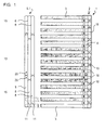
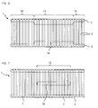
- the overall structure of the mobile couch base is in particular in Figures 1, 6 and 7 can be seen.
- the mobile bed base 1 has two spaced apart and parallel to each other, elastically deformable longitudinal spars 2.
- the two longitudinal spars 2 are by means of a plurality of parallel, extending transversely to the longitudinal direction of the longitudinal spars 2 Crossbars 3 connected to each other.
- Each longitudinal spar 2 exists from a, preferably textile sleeve 4, in which a Shaped body 5 takes place.
- This molded body 5 is as inflatable element 7 designed.
- These inflatable elements 7, which have the shape of a tube, would be in themselves insufficient longitudinal stability.
- Stabilizing means 6 are provided, which are designed differently could be. In a preferred embodiment, as can be seen in FIG.
- Stabilizing means 6 are provided as longitudinal webs 11.
- the Longitudinal webs 11 divide the inflatable accordingly Element 7 in three parallel chambers 8.
- Die Longitudinal webs 11 as stabilizing means 6 cause the molded bodies 5 or the inflatable elements 7 under load pressure hardly from the longitudinal direction deviatingly deform to the outside.
- the longitudinal webs 11 are implemented in the inflatable element 7 Partitions and not just welds, the lower part and connect the top with each other. This has a significant impact higher stabilizing effect than just the bottom and Weld seams directly connecting the top. At the same time you achieve a higher cross-section, which the Comfort increased.
- the inflatable elements can also be in the longitudinal direction additionally be divided. This is clear in Figure 1 evident. Different areas can be formed in this way. In particular the middle area in relation to the longitudinal extent must take on the greatest load capacity. For one Thanks to the subdivision into the longitudinal direction of this area 13 inflated more become. Those adjoining the middle area 13 End regions 15, 15 'can correspond to the load be inflated to different degrees. The area 15 represents the head area and the area 15 'the leg area.
- the individual sections of the inflatable elements 7, which through the longitudinal webs serving as stabilizing means 6 11 are divided into the corresponding area be designed to communicate with each other. This can be so happen that only two of the three chambers together can communicate while the third is separately inflatable is. However, all three chambers become easier together design communicating. If in the represented here Variants in particular the subdivision of the molded body 5 in three longitudinal chambers 8 is shown, this is in turn as preferred solution to look at, although in different applications, two parallel chambers 8 are sufficient. This is mainly due to the overall breadth of the Bed base 1 dependent.
- the actual connecting fastening between the longitudinal spar 2 and crossbar 3 is designated by 21 in total.
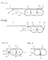
- She consists, as shown in Figures 2a and 3a, on the one hand Bands 22 which are transverse to the longitudinal direction of the casing and opposite longitudinal spar are sewn facing.
- the free ends of the straps 22 have a buttonhole 23.
- This buttonhole 23 is used on the crossbar 3 at the Button-like elements 24 attached on the lower side to record.
- the fastening straps 22 are so short designed that the crossbars 3 even when not inflated Condition of the inflatable elements 7 not out of the pockets 10 can slide out. Only if the tapes 22 from the button-like Element 24 are solved, the crossbars 3 from the Pull out pockets 10. This way you can easily deflate the inflatable elements 7 and then the entire one Fold the bed base with the crossbars 3 or roll up without the whole bed base in its Parts falling apart.
- FIGS. 2b and 3c and in FIG. 3b Further advantageous embodiments of the connection between the longitudinal spar 2 and the crossbar 3 are shown in FIGS. 2b and 3c and in FIG. 3b.
- the straps 22 can also be sewn onto a peripheral strip 41 of the sheath 4 or attached in some other way.
- the buttonholes 23 can also be made directly in the bar 41, which allows the bands 22 to be omitted.
- a zipper 42 which extends at least partially laterally along the sheath 4 facilitates access to the elements 7 located on the inside. In one embodiment, as shown in FIG. 2b, the zipper could also be dispensed with.
- the parts of the sheath 4 which overlap in the area of the edge 41 would then not be sewn directly to one another, glued or otherwise connected and would be held together by the dowel buttons 24 on the slats 3.
- the elements 7 that are accessible by means of a zipper or a button placket inflation and deflation is no problem.
- the closable openings 18 In the case of a closed casing 4, as can be seen in FIG. 3a, the closable openings 18 must be fitted in order to reach the valves 20 on the inside.
- the closable opening 18 therefore consists of a corresponding tab which can be closed, for example, by means of a Velcro fastener 19.
- the valve and correspondingly also the closable opening 18 are located on the underside of the longitudinal spar 2.
- a push button system or a strong Velcro system can also be used.
- the molded bodies 5, which are shaped as inflatable elements 7, are held removably in the casing 4.
- the cover 4 has an opening which is present at least in the end region and which can be closed, for example, by a zipper 42.
- the zipper 42 is only shown schematically here.
- This design also has hygienic advantages, so the sleeves 4 with the bands 22, which are sewn onto the sleeves 4 by means of the sewing seams 25, can be removed and washed or dry-cleaned.
- the inflatable element 7 can be easily replaced or patched if it should have a leak.
- stabilizing means 6 in the form of bars 16.
- these are rods 16, which on the outside of the casing 4 by means of loops 26 are held. It is also conceivable that the rods 16 in such loops are held within the shell 4 to arrange.
- This additional stabilizing means 6 in the form of Bars 16 can only refer to those areas restrict in which the shaped body 5 in the longitudinal direction are divided to the areas mentioned earlier 13, 15 and 15 '. However, there is one in FIG Variant shown, which is particularly preferred in this regard.
- the stabilizing means 6 serving longitudinal webs 11 are designed here that at least one of the chambers 8 is longer than the others and so from their area, for example 15, in the neighboring ones Area, here protrudes for example 13. This will the weak point in the area of the longitudinal subdivision considerably stiffened.
Landscapes
- Mattresses And Other Support Structures For Chairs And Beds (AREA)
Applications Claiming Priority (2)
| Application Number | Priority Date | Filing Date | Title |
|---|---|---|---|
| CH171199 | 1999-09-17 | ||
| CH171199 | 1999-09-17 |
Publications (1)
| Publication Number | Publication Date |
|---|---|
| EP1084664A1 true EP1084664A1 (fr) | 2001-03-21 |
Family
ID=4216823
Family Applications (1)
| Application Number | Title | Priority Date | Filing Date |
|---|---|---|---|
| EP00810808A Withdrawn EP1084664A1 (fr) | 1999-09-17 | 2000-09-07 | Support de couchage mobile |
Country Status (1)
| Country | Link |
|---|---|
| EP (1) | EP1084664A1 (fr) |
Cited By (1)
| Publication number | Priority date | Publication date | Assignee | Title |
|---|---|---|---|---|
| WO2007131370A1 (fr) * | 2006-05-15 | 2007-11-22 | Peter Meili | Support de couchage mobile |
Citations (7)
| Publication number | Priority date | Publication date | Assignee | Title |
|---|---|---|---|---|
| EP0116237A1 (fr) | 1983-01-06 | 1984-08-22 | Gordon Douglas Griffin | Système de support pour le corps humain |
| EP0243383B1 (fr) | 1985-10-22 | 1990-12-27 | Hüsler-Liforma Entwicklungs AG | Installation de repos, notamment pour lit |
| DE3933816A1 (de) | 1989-10-10 | 1991-04-18 | Alpha Patentverwertungs Ges M | Bettunterbau |
| US5070560A (en) * | 1990-10-22 | 1991-12-10 | Healthflex, Inc. | Pressure relief support system for a mattress |
| DE4212037A1 (de) * | 1992-04-10 | 1993-10-14 | Christian Schlesinger | Liegeneinrichtung |
| DE4302778A1 (de) * | 1993-02-02 | 1994-08-04 | Melanie Laengle | Liegefläche für Betten, Sofas und dergleichen mit Luftversorgung |
| DE4409093A1 (de) * | 1994-03-17 | 1995-09-21 | Wesemann Rolf | Auflagefläche, insbesondere für ein Liegemöbel |
-
2000
- 2000-09-07 EP EP00810808A patent/EP1084664A1/fr not_active Withdrawn
Patent Citations (7)
| Publication number | Priority date | Publication date | Assignee | Title |
|---|---|---|---|---|
| EP0116237A1 (fr) | 1983-01-06 | 1984-08-22 | Gordon Douglas Griffin | Système de support pour le corps humain |
| EP0243383B1 (fr) | 1985-10-22 | 1990-12-27 | Hüsler-Liforma Entwicklungs AG | Installation de repos, notamment pour lit |
| DE3933816A1 (de) | 1989-10-10 | 1991-04-18 | Alpha Patentverwertungs Ges M | Bettunterbau |
| US5070560A (en) * | 1990-10-22 | 1991-12-10 | Healthflex, Inc. | Pressure relief support system for a mattress |
| DE4212037A1 (de) * | 1992-04-10 | 1993-10-14 | Christian Schlesinger | Liegeneinrichtung |
| DE4302778A1 (de) * | 1993-02-02 | 1994-08-04 | Melanie Laengle | Liegefläche für Betten, Sofas und dergleichen mit Luftversorgung |
| DE4409093A1 (de) * | 1994-03-17 | 1995-09-21 | Wesemann Rolf | Auflagefläche, insbesondere für ein Liegemöbel |
Cited By (1)
| Publication number | Priority date | Publication date | Assignee | Title |
|---|---|---|---|---|
| WO2007131370A1 (fr) * | 2006-05-15 | 2007-11-22 | Peter Meili | Support de couchage mobile |
Similar Documents
| Publication | Publication Date | Title |
|---|---|---|
| DE3936788C2 (fr) | ||
| DE9103109U1 (de) | Unterlage für ein Kleinkind | |
| CH670945A5 (en) | Under-frame for bed or couch | |
| EP1622482B1 (fr) | Sac de couchage a suspendre | |
| EP0422416B1 (fr) | Bâti pour lit | |
| DE3587813T2 (de) | Deckenstruktur für möbel umschläge, paneele und ähnliches. | |
| DE102018130113B4 (de) | Kopfteil für ein Bett, insbesondere ein Boxspringbett | |
| EP1084664A1 (fr) | Support de couchage mobile | |
| DE202004000608U1 (de) | Ausziehbare Liegen in einem Fahrzeug, insbesondere auf der Fahrer- und Beifahrerseite | |
| EP2020888B1 (fr) | Support de couchage mobile | |
| DE3238795A1 (de) | Schlafsack | |
| EP1063909B1 (fr) | Sommier a lattes multicouches, destine notamment a du mobilier pour s'asseoir et s'allonger | |
| WO1996028072A1 (fr) | Grille de lattes pour literies et sieges | |
| DE19923391C1 (de) | Matratze | |
| DE2303264A1 (de) | Moebel, insbesondere liegemoebel | |
| DE102009040603B4 (de) | Faltklappbett | |
| DE19514945A1 (de) | Luftmatratze | |
| CH695083A5 (de) | Liege- oder Sitzunterlage. | |
| DE2261070A1 (de) | Sitz-liege-kombimoebel | |
| DE1654374C (de) | Matratze | |
| DE29508965U1 (de) | Matratze mit integriertem Lattenrost | |
| EP1498052A1 (fr) | Lit | |
| EP1076498B1 (fr) | Support pour coussin | |
| AT162666B (de) | Stiz- und Liegemöbel | |
| CH689219A5 (de) | Zusammenrollbare Gesundheitsmatratze. |
Legal Events
| Date | Code | Title | Description |
|---|---|---|---|
| PUAI | Public reference made under article 153(3) epc to a published international application that has entered the european phase |
Free format text: ORIGINAL CODE: 0009012 |
|
| AK | Designated contracting states |
Kind code of ref document: A1 Designated state(s): AT BE CH CY DE DK ES FI FR GB GR IE IT LI LU MC NL PT SE |
|
| AX | Request for extension of the european patent |
Free format text: AL;LT;LV;MK;RO;SI |
|
| 17P | Request for examination filed |
Effective date: 20010910 |
|
| AKX | Designation fees paid |
Free format text: AT BE CH CY DE DK ES FI FR GB GR IE IT LI LU MC NL PT SE |
|
| AXX | Extension fees paid |
Free format text: AL PAYMENT 20010910;LT PAYMENT 20010910;LV PAYMENT 20010910;MK PAYMENT 20010910;RO PAYMENT 20010910;SI PAYMENT 20010910 |
|
| GRAP | Despatch of communication of intention to grant a patent |
Free format text: ORIGINAL CODE: EPIDOSNIGR1 |
|
| STAA | Information on the status of an ep patent application or granted ep patent |
Free format text: STATUS: THE APPLICATION IS DEEMED TO BE WITHDRAWN |
|
| 18D | Application deemed to be withdrawn |
Effective date: 20040301 |