EP1084764A1 - Abgabevorrichtung für einen Behälter - Google Patents
Abgabevorrichtung für einen Behälter Download PDFInfo
- Publication number
- EP1084764A1 EP1084764A1 EP00402556A EP00402556A EP1084764A1 EP 1084764 A1 EP1084764 A1 EP 1084764A1 EP 00402556 A EP00402556 A EP 00402556A EP 00402556 A EP00402556 A EP 00402556A EP 1084764 A1 EP1084764 A1 EP 1084764A1
- Authority
- EP
- European Patent Office
- Prior art keywords
- piston
- control member
- closing
- base part
- pumping chamber
- Prior art date
- Legal status (The legal status is an assumption and is not a legal conclusion. Google has not performed a legal analysis and makes no representation as to the accuracy of the status listed.)
- Granted
Links
Images


Classifications
-
- B—PERFORMING OPERATIONS; TRANSPORTING
- B05—SPRAYING OR ATOMISING IN GENERAL; APPLYING FLUENT MATERIALS TO SURFACES, IN GENERAL
- B05B—SPRAYING APPARATUS; ATOMISING APPARATUS; NOZZLES
- B05B11/00—Single-unit hand-held apparatus in which flow of contents is produced by the muscular force of the operator at the moment of use
- B05B11/01—Single-unit hand-held apparatus in which flow of contents is produced by the muscular force of the operator at the moment of use characterised by the means producing the flow
- B05B11/10—Pump arrangements for transferring the contents from the container to a pump chamber by a sucking effect and forcing the contents out through the dispensing nozzle
- B05B11/1001—Piston pumps
-
- A—HUMAN NECESSITIES
- A47—FURNITURE; DOMESTIC ARTICLES OR APPLIANCES; COFFEE MILLS; SPICE MILLS; SUCTION CLEANERS IN GENERAL
- A47K—SANITARY EQUIPMENT; ACCESSORIES THEREFOR, e.g. TOILET ACCESSORIES
- A47K5/00—Holders or dispensers for soap, toothpaste or the like
- A47K5/06—Dispensers for soap
- A47K5/12—Dispensers for soap for liquid or pasty soap
- A47K5/1202—Dispensers for soap for liquid or pasty soap dispensing dosed volume
- A47K5/1204—Dispensers for soap for liquid or pasty soap dispensing dosed volume by means of a rigid dispensing chamber and pistons
- A47K5/1207—Dispensing from the bottom of the dispenser with a vertical piston
-
- B—PERFORMING OPERATIONS; TRANSPORTING
- B05—SPRAYING OR ATOMISING IN GENERAL; APPLYING FLUENT MATERIALS TO SURFACES, IN GENERAL
- B05B—SPRAYING APPARATUS; ATOMISING APPARATUS; NOZZLES
- B05B11/00—Single-unit hand-held apparatus in which flow of contents is produced by the muscular force of the operator at the moment of use
- B05B11/01—Single-unit hand-held apparatus in which flow of contents is produced by the muscular force of the operator at the moment of use characterised by the means producing the flow
- B05B11/10—Pump arrangements for transferring the contents from the container to a pump chamber by a sucking effect and forcing the contents out through the dispensing nozzle
- B05B11/1042—Components or details
- B05B11/1066—Pump inlet valves
-
- B—PERFORMING OPERATIONS; TRANSPORTING
- B05—SPRAYING OR ATOMISING IN GENERAL; APPLYING FLUENT MATERIALS TO SURFACES, IN GENERAL
- B05B—SPRAYING APPARATUS; ATOMISING APPARATUS; NOZZLES
- B05B11/00—Single-unit hand-held apparatus in which flow of contents is produced by the muscular force of the operator at the moment of use
- B05B11/01—Single-unit hand-held apparatus in which flow of contents is produced by the muscular force of the operator at the moment of use characterised by the means producing the flow
- B05B11/10—Pump arrangements for transferring the contents from the container to a pump chamber by a sucking effect and forcing the contents out through the dispensing nozzle
- B05B11/1094—Pump arrangements for transferring the contents from the container to a pump chamber by a sucking effect and forcing the contents out through the dispensing nozzle having inlet or outlet valves not being actuated by pressure or having no inlet or outlet valve
-
- G—PHYSICS
- G01—MEASURING; TESTING
- G01F—MEASURING VOLUME, VOLUME FLOW, MASS FLOW OR LIQUID LEVEL; METERING BY VOLUME
- G01F11/00—Apparatus requiring external operation adapted at each repeated and identical operation to measure and separate a predetermined volume of fluid or fluent solid material from a supply or container, without regard to weight, and to deliver it
- G01F11/02—Apparatus requiring external operation adapted at each repeated and identical operation to measure and separate a predetermined volume of fluid or fluent solid material from a supply or container, without regard to weight, and to deliver it with measuring chambers which expand or contract during measurement
- G01F11/021—Apparatus requiring external operation adapted at each repeated and identical operation to measure and separate a predetermined volume of fluid or fluent solid material from a supply or container, without regard to weight, and to deliver it with measuring chambers which expand or contract during measurement of the piston type
- G01F11/025—Apparatus requiring external operation adapted at each repeated and identical operation to measure and separate a predetermined volume of fluid or fluent solid material from a supply or container, without regard to weight, and to deliver it with measuring chambers which expand or contract during measurement of the piston type with manually operated pistons
-
- B—PERFORMING OPERATIONS; TRANSPORTING
- B05—SPRAYING OR ATOMISING IN GENERAL; APPLYING FLUENT MATERIALS TO SURFACES, IN GENERAL
- B05B—SPRAYING APPARATUS; ATOMISING APPARATUS; NOZZLES
- B05B11/00—Single-unit hand-held apparatus in which flow of contents is produced by the muscular force of the operator at the moment of use
- B05B11/0005—Components or details
- B05B11/0059—Components or details allowing operation in any orientation, e.g. for discharge in inverted position
Definitions
- the present invention relates to a distribution device intended to equip a container, in particular a container containing a cosmetic product, comprising a base part and a set movable relative to this base part, defining with the latter a variable volume pumping chamber.
- the mobile assembly comprises a piston movable between two positions extremes and a control member, this control member being integral with the piston and passing through the base part and being provided with an outlet passage allowing the distribution of the product contained in the pumping chamber, the piston comprising at less a supply passage allowing the filling of the pumping chamber, the control member being movable relative to the piston between a position of dispensing and a filling position, the piston comprising means closing the outlet passage, suitable for closing the latter when the control is in its filling position and / or the control member comprising means for closing the intake passage, capable of closing the latter when the control member is in its dispensing position, the control member comprising a first drive means arranged to cooperate with the piston when the control member is in its dispensing position to drive it in displacement in a direction corresponding to a reduction in the volume of the pumping, the control member comprising a second drive means arranged to cooperate with the piston when the control member
- the invention aims to further improve a device of the type defined above.
- the base part is shaped to create a friction between the piston and the base part when the volume of the pumping chamber is minimum, and no friction or less friction when the piston is in an intermediate position between its extreme positions.
- the piston can move without rubbing on the base part or with a less friction during filling of the pumping chamber, which decreases wear of the components and facilitates the handling of the control member.
- the basic part is shaped to create friction between the piston and the base part when the volume of the pumping chamber is maximum and an absence of friction between the piston and the basic part when the piston is in an intermediate position between its positions extremes.
- the base part comprises at least one first portion with an inside diameter less than or equal to the outside diameter of the piston and a second portion with a diameter larger than that of the piston, the first portion coming into contact with the piston when the volume of the pumping chamber is minimum.
- the base part comprises a third portion of a diameter less than or equal to that of the piston, and coming into contact with the piston when the volume of the pumping chamber is maximum.
- the axial dimension of the first and third portions of the base portion is less than or equal to twice the dimension axial of the piston.
- the dispensing device according to the invention has a reduced number of parts, inexpensive to manufacture and have reliable operation.
- the piston includes means for closing the passage of outlet suitable for closing the latter when the control member is in its position filling and the control member comprises means for closing the passage suitable for closing the latter when the control member is in its distribution position.
- the piston includes means for closing the outlet passage suitable for closing the latter when the control member is in its position filling, and means for closing off the supply passage.
- control member includes shutter means of the own supply passage to close off the latter when the control member is in its dispensing position, and means for closing the outlet passage.
- the means for closing the intake passage play the role of the first means of training.
- the piston consists of a disc provided a central light for the passage of the control member and filling distributed around this central light, these filling orifices constituting the intake passage.
- control member comprises a rod control extending at one end outside the base part, provided therewith end of a gripping element and an outlet for the product.
- control rod has at its opposite end, after crossing the piston, a plate capable of closing the passage of the piston when the control member is in its dispensing position.
- the tray has openings favoring the circulation of the product towards the inlet passage of the piston.
- the second drive means is constituted by a stop made on the control rod.
- the outlet passage opens out through an orifice radial on the control rod between the first and second drive means and the means for closing the outlet passage consists of a cylindrical surface of the central light of the piston, said cylindrical surface having a height less than the distance between said radial orifice and the first drive means and a height greater than the distance between said radial orifice and the second drive means.
- the base part is shaped to increase the friction of the piston on the base part when the volume of the chamber pumping is minimum or maximum.
- the base part is arranged to be fixed on the neck of the container.
- the invention also relates to a container equipped with a device for distribution as defined above.
- the invention also relates to the use of a container as mentioned above, head below.
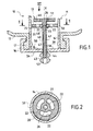
- the distribution device or pump 10 shown in the figures comprises a base part 11 secured to a container 12 and a movable assembly 13, displaceable with respect to the base part 11, as will be explained later.
- the base part 11 comprises a tubular skirt 14 of axis X, closed at its lower end by a bottom wall 15, this bottom wall 15 being extended radially outside the tubular skirt 14 by an annular rim 16 shaped to snap onto the neck 17 of the container 12.
- the container 12 is intended to be used upside down.
- the tubular skirt 14 seals the neck 17 of the container.
- the movable assembly 13 comprises a piston 20 and a control member 40.
- the piston 20 is presented in the embodiment described in the form of a disc with an outside diameter close to the inside diameter of the tubular skirt 14, crossed in its center by a central light 21.
- the piston 20 is also crossed by distributed filling orifices 22 around this central light 21.
- the filling orifices 22 have a reniform section, as is can see it in figure 2.
- the piston 20 defines inside the tubular skirt 14, with the bottom wall 15, a pumping chamber 30 whose volume depends on the axial positioning of the piston 20 relative to the base part 11.
- the control member 40 comprises a control rod 41 of axis X, internally provided with a channel 42.
- the control rod 41 passes through the bottom wall 15 thanks to a opening 44 and passes through the central lumen 21 of the piston 20.
- the channel 42 opens firstly at the lower end of the rod control 41 through an axial orifice 43 and on the other hand at a certain distance from the upper end of the control rod 41 by a radial orifice 45.
- the control rod 41 is secured at its upper end to a plate 46.
- This plate 46 extends perpendicular to the axis X.
- the outer diameter of the plate 46 is chosen so as to allow it to cover the filling orifices 22, as will be explained later.
- the control rod 41 has a stop 48 located under the radial orifice 45.
- the spacing between the radial orifice 45 and the plate 46 is greater than the thickness of the piston 20, so that the control rod 41 can move relative to the piston 20 enters a filling position shown in Figure 1, in which the piston 20 is supported on the stop 48 by its lower face 25 and closes with the surface cylindrical 26 of the central lumen 21 the radial opening 45, and a position of distribution shown in Figure 3, in which the piston 20 is supported by its upper face 29 against the plate 46.
- the spacing between the stop 48 and the plate 46 is greater than the thickness of the piston 20 and chosen so that when the piston 20 rests against the plate 46, the radial orifice 45 is released, as can be seen in FIG. 3.
- the tubular skirt 14 has on its inner surface slight reliefs 50 intended to increase the friction of the piston 20 on the tubular skirt 14 when the piston 20 is in the position of FIG. 1 corresponding to a volume of the maximum pumping or when the piston is in the position of the corresponding figure 4 at a minimum volume of the pumping chamber 30.
- the plate 46 has openings 51 offset relative to the orifices of filling 22, intended to promote the circulation of the product contained in the container 12 to the filling orifices 22 when the pumping chamber 30 is being filling.
- the orifices 51 are reniform, as can be seen in FIG. 7.
- the control rod 41 is secured at its lower end to a tip distribution 53 also constituting a gripping member.
- the operation of the dispensing device is as follows.
- the user pulls on the dispensing nozzle 53, this which causes the rod 41 to move down.
- the volume of the pumping chamber 30 decreases and the product flows through the channel 42 to outlet 43.
- the clearance between the piston 20 and the tubular skirt 14 is sufficiently small so that the product contained in the pumping chamber 30 flows preferentially through channel 42 rather than through this game.
- the volume of the pumping chamber 30 increases and a vacuum is created in it, causing the arrival of product from the container, by the openings 51 and the filling orifices 22, as illustrated in FIG. 6.
- FIG. 8 shows a first variant 10 ′ in which the mobile assembly 13 'comprises a control member 40' which differs the control member 40 previously described by the absence of the plate 46, replaced by a simple shoulder 46 'and a piston 20' which differs from piston 20 previously described by the presence of valves 80 associated with the filling orifices 22 on the lower side.
- valves 80 When filling the pumping chamber 30, the valves 80 open.
- valves 80 then close to close the filling orifices 22.
- the radial orifice 45 is cleared to allow the distribution of the product.
- FIG. 9 shows a second variant 10 "in which the mobile assembly 13 "differs from the mobile assembly 13 in that the passage of outlet of the control member 40 "has a radial orifice 45" opening into the pumping chamber 30 below the stop 48 and by the fact that a valve 90 is associated at outlet 43.
- the latter opens when the user pulls on the 40 "control member to dispense the product contained in the pumping chamber 30.
- valves 80 and 90 of the two variants which have just been described are advantageously produced by overmolding or bi-injection in an elastomeric material.
Landscapes
- Health & Medical Sciences (AREA)
- Public Health (AREA)
- Physics & Mathematics (AREA)
- Fluid Mechanics (AREA)
- General Physics & Mathematics (AREA)
- Containers And Packaging Bodies Having A Special Means To Remove Contents (AREA)
- Sampling And Sample Adjustment (AREA)
- Devices For Dispensing Beverages (AREA)
- Reciprocating Pumps (AREA)
- Closures For Containers (AREA)
Applications Claiming Priority (2)
| Application Number | Priority Date | Filing Date | Title |
|---|---|---|---|
| FR9911581A FR2798650B1 (fr) | 1999-09-16 | 1999-09-16 | Dispositif de distribution destine a equiper un recipient |
| FR9911581 | 1999-09-16 |
Publications (2)
| Publication Number | Publication Date |
|---|---|
| EP1084764A1 true EP1084764A1 (de) | 2001-03-21 |
| EP1084764B1 EP1084764B1 (de) | 2006-09-13 |
Family
ID=9549912
Family Applications (1)
| Application Number | Title | Priority Date | Filing Date |
|---|---|---|---|
| EP00402556A Expired - Lifetime EP1084764B1 (de) | 1999-09-16 | 2000-09-15 | Abgabevorrichtung für einen Behälter |
Country Status (8)
| Country | Link |
|---|---|
| US (1) | US6655556B1 (de) |
| EP (1) | EP1084764B1 (de) |
| JP (1) | JP3656023B2 (de) |
| AT (1) | ATE339255T1 (de) |
| CA (1) | CA2319960C (de) |
| DE (1) | DE60030649T2 (de) |
| ES (1) | ES2270797T3 (de) |
| FR (1) | FR2798650B1 (de) |
Cited By (3)
| Publication number | Priority date | Publication date | Assignee | Title |
|---|---|---|---|---|
| WO2007043866A1 (en) * | 2005-10-10 | 2007-04-19 | Adso Bvba | Device for metered dispensing of a pasty mass, and a container therefor |
| WO2018010889A1 (de) * | 2016-07-14 | 2018-01-18 | F. Holzer Gmbh | Pumpkopf sowie dosiervorrichtung |
| US11221248B2 (en) | 2016-07-14 | 2022-01-11 | F. Holzer Gmbh | Pump head and metering device |
Families Citing this family (4)
| Publication number | Priority date | Publication date | Assignee | Title |
|---|---|---|---|---|
| DE20206065U1 (de) * | 2002-04-18 | 2003-09-04 | Finnah Engineering und Packaging GmbH, 48683 Ahaus | Dosiervorrichtung für fließfähige Produkte |
| US20110220138A1 (en) * | 2010-03-09 | 2011-09-15 | Roberts Michelle A | Apparatus and system for a fingernail cleaning device |
| US8827119B2 (en) * | 2013-01-23 | 2014-09-09 | Gojo Industries, Inc. | Pull pumps, refill units and dispensers for pull pumps |
| US9688524B2 (en) * | 2013-04-25 | 2017-06-27 | Discma Ag | Injection device for injecting a product in a container or a preform |
Citations (4)
| Publication number | Priority date | Publication date | Assignee | Title |
|---|---|---|---|---|
| GB749691A (en) * | 1953-05-18 | 1956-05-30 | Deb Chemical Proprietaries Ltd | Reciprocating pumps for dispensing measured quantities of cream, paste, gels and other viscous substances |
| EP0011487A1 (de) | 1978-11-21 | 1980-05-28 | Sterwin Ag. | Vorrichtung zur Verteilung viskoser Substanzen wie Pasten oder Creme |
| EP0312474A1 (de) * | 1987-10-14 | 1989-04-19 | THEARD, Moise | Automatischer Spender für pastöse Massen |
| US5024355A (en) * | 1988-12-20 | 1991-06-18 | Societe Technique de Pulverisation--STEP | Device for dispensing a liquid or a cream in small-volume drops, and an associated dispensing assembly |
Family Cites Families (7)
| Publication number | Priority date | Publication date | Assignee | Title |
|---|---|---|---|---|
| US1300183A (en) * | 1918-04-22 | 1919-04-08 | Luxe Brush Company De | Liquid-dispensing device. |
| US2885121A (en) * | 1957-03-19 | 1959-05-05 | Joseph A Pinkard | Semi-automatic injector for liquid fungicide |
| US3759425A (en) * | 1970-06-23 | 1973-09-18 | Cooper Mcdougall & Robertson | Piston valve syringe gun |
| US3786966A (en) * | 1971-10-26 | 1974-01-22 | Masonry Syst Int | Apparatus for dispensing flowable high-density material |
| DE3723309A1 (de) * | 1987-07-15 | 1989-01-26 | Fischbach A Kunststoff Kg | Mischvorrichtung |
| US5172834A (en) * | 1990-12-26 | 1992-12-22 | Philip Wang | Dispensing container converting reciprocating motion to rotary motion to move a product dispensing piston to dispense the product in a fixed amount |
| GB9512535D0 (en) | 1995-06-20 | 1995-08-23 | Douglas Plastics Ltd | Fastener |
-
1999
- 1999-09-16 FR FR9911581A patent/FR2798650B1/fr not_active Expired - Fee Related
-
2000
- 2000-09-15 CA CA002319960A patent/CA2319960C/fr not_active Expired - Fee Related
- 2000-09-15 DE DE60030649T patent/DE60030649T2/de not_active Expired - Fee Related
- 2000-09-15 EP EP00402556A patent/EP1084764B1/de not_active Expired - Lifetime
- 2000-09-15 AT AT00402556T patent/ATE339255T1/de not_active IP Right Cessation
- 2000-09-15 ES ES00402556T patent/ES2270797T3/es not_active Expired - Lifetime
- 2000-09-18 US US09/664,053 patent/US6655556B1/en not_active Expired - Fee Related
- 2000-09-18 JP JP2000282411A patent/JP3656023B2/ja not_active Expired - Fee Related
Patent Citations (4)
| Publication number | Priority date | Publication date | Assignee | Title |
|---|---|---|---|---|
| GB749691A (en) * | 1953-05-18 | 1956-05-30 | Deb Chemical Proprietaries Ltd | Reciprocating pumps for dispensing measured quantities of cream, paste, gels and other viscous substances |
| EP0011487A1 (de) | 1978-11-21 | 1980-05-28 | Sterwin Ag. | Vorrichtung zur Verteilung viskoser Substanzen wie Pasten oder Creme |
| EP0312474A1 (de) * | 1987-10-14 | 1989-04-19 | THEARD, Moise | Automatischer Spender für pastöse Massen |
| US5024355A (en) * | 1988-12-20 | 1991-06-18 | Societe Technique de Pulverisation--STEP | Device for dispensing a liquid or a cream in small-volume drops, and an associated dispensing assembly |
Cited By (4)
| Publication number | Priority date | Publication date | Assignee | Title |
|---|---|---|---|---|
| WO2007043866A1 (en) * | 2005-10-10 | 2007-04-19 | Adso Bvba | Device for metered dispensing of a pasty mass, and a container therefor |
| WO2018010889A1 (de) * | 2016-07-14 | 2018-01-18 | F. Holzer Gmbh | Pumpkopf sowie dosiervorrichtung |
| US11110472B2 (en) | 2016-07-14 | 2021-09-07 | F. Holzer Gmbh | Pump head and metering device |
| US11221248B2 (en) | 2016-07-14 | 2022-01-11 | F. Holzer Gmbh | Pump head and metering device |
Also Published As
| Publication number | Publication date |
|---|---|
| US6655556B1 (en) | 2003-12-02 |
| EP1084764B1 (de) | 2006-09-13 |
| DE60030649T2 (de) | 2007-09-13 |
| FR2798650A1 (fr) | 2001-03-23 |
| FR2798650B1 (fr) | 2002-01-04 |
| CA2319960A1 (fr) | 2001-03-16 |
| JP3656023B2 (ja) | 2005-06-02 |
| CA2319960C (fr) | 2005-02-01 |
| JP2001165037A (ja) | 2001-06-19 |
| ATE339255T1 (de) | 2006-10-15 |
| DE60030649D1 (de) | 2006-10-26 |
| ES2270797T3 (es) | 2007-04-16 |
Similar Documents
| Publication | Publication Date | Title |
|---|---|---|
| EP0757592B1 (de) | Pumpe mit vordruckaufbau | |
| EP0733559B1 (de) | Spender für flüssige oder pastöse Produkte, insbesondere zur Verwendung in Kosmetika | |
| EP0623060B1 (de) | Vordruckpumpe | |
| EP2336079B1 (de) | Vorrichtung zum Befüllen von Behältnissen | |
| EP0714836B1 (de) | Betätigungsvorrichtung für des Abgabeventil eines Aerosolbehälters | |
| FR2802187A1 (fr) | Dispositif de distribution d'un produit, comportant un flacon loge dans un recipient | |
| FR2668958A1 (fr) | Dispositif de pulverisation ou de distribution de produit fluide, a aspiration du produit contenu dans le canal de sortie en fin d'actionnement. | |
| EP1751020B1 (de) | Unbelüfteter flüssigkeitsspender | |
| FR3037577A1 (fr) | Systeme et procede de re-remplissage en liquide d'un flacon | |
| FR2693174A1 (fr) | Perfectionnements aux dispositifs distributeur et doseur de produit. | |
| FR2662194A1 (fr) | Mecanisme de chasse interrompable, a ecoulement minimal assure. | |
| FR2577825A1 (fr) | Distributeur de produit visqueux a pompe incorporee | |
| FR2627460A1 (fr) | Distributeur pour produit pateux comprenant un poussoir axial a distribution laterale et un element de masquage de son orifice de sortie | |
| EP1084764B1 (de) | Abgabevorrichtung für einen Behälter | |
| FR2742812A1 (fr) | Pompe a precompression formee dans le poussoir | |
| EP1004523A1 (de) | Ventil für die Abgabe von Fluid unter Druck | |
| EP0522218A1 (de) | Druckknopfspülmechanismus mit eintauchbarem Körper | |
| FR2814727A1 (fr) | Valve destinee a equiper un dispositif pour la distribution sous pression d'un produit, et dispositif ainsi equipe | |
| EP1083004B1 (de) | Pumpe für einen Behälter | |
| FR2692040A1 (fr) | Dispositif doseur pour substance fluide. | |
| EP1497039B1 (de) | Abgabepumpe für medien | |
| FR2727670A1 (fr) | Dispositif pour prelever dans un recipient une dose d'un produit, notamment cosmetique, et pour appliquer cette dose | |
| EP1230031B1 (de) | Pumpe mit schneller hin- und herbewegung | |
| FR2889692A1 (fr) | Dispositif de distribution d'un produit fluide | |
| FR2889691A1 (fr) | Dispositif de distribution d'un produit fluide sous forme de goutte |
Legal Events
| Date | Code | Title | Description |
|---|---|---|---|
| PUAI | Public reference made under article 153(3) epc to a published international application that has entered the european phase |
Free format text: ORIGINAL CODE: 0009012 |
|
| 17P | Request for examination filed |
Effective date: 20000922 |
|
| AK | Designated contracting states |
Kind code of ref document: A1 Designated state(s): AT BE CH CY DE DK ES FI FR GB GR IE IT LI LU MC NL PT SE |
|
| AX | Request for extension of the european patent |
Free format text: AL;LT;LV;MK;RO;SI |
|
| AKX | Designation fees paid |
Free format text: AT BE CH CY DE DK ES FI FR GB GR IE IT LI LU MC NL PT SE |
|
| GRAP | Despatch of communication of intention to grant a patent |
Free format text: ORIGINAL CODE: EPIDOSNIGR1 |
|
| GRAS | Grant fee paid |
Free format text: ORIGINAL CODE: EPIDOSNIGR3 |
|
| GRAA | (expected) grant |
Free format text: ORIGINAL CODE: 0009210 |
|
| AK | Designated contracting states |
Kind code of ref document: B1 Designated state(s): AT BE CH CY DE DK ES FI FR GB GR IE IT LI LU MC NL PT SE |
|
| PG25 | Lapsed in a contracting state [announced via postgrant information from national office to epo] |
Ref country code: AT Free format text: LAPSE BECAUSE OF FAILURE TO SUBMIT A TRANSLATION OF THE DESCRIPTION OR TO PAY THE FEE WITHIN THE PRESCRIBED TIME-LIMIT Effective date: 20060913 Ref country code: FI Free format text: LAPSE BECAUSE OF FAILURE TO SUBMIT A TRANSLATION OF THE DESCRIPTION OR TO PAY THE FEE WITHIN THE PRESCRIBED TIME-LIMIT Effective date: 20060913 Ref country code: IE Free format text: LAPSE BECAUSE OF FAILURE TO SUBMIT A TRANSLATION OF THE DESCRIPTION OR TO PAY THE FEE WITHIN THE PRESCRIBED TIME-LIMIT Effective date: 20060913 Ref country code: NL Free format text: LAPSE BECAUSE OF FAILURE TO SUBMIT A TRANSLATION OF THE DESCRIPTION OR TO PAY THE FEE WITHIN THE PRESCRIBED TIME-LIMIT Effective date: 20060913 |
|
| REG | Reference to a national code |
Ref country code: GB Ref legal event code: FG4D Free format text: NOT ENGLISH |
|
| REG | Reference to a national code |
Ref country code: CH Ref legal event code: EP |
|
| PG25 | Lapsed in a contracting state [announced via postgrant information from national office to epo] |
Ref country code: BE Free format text: LAPSE BECAUSE OF NON-PAYMENT OF DUE FEES Effective date: 20060930 Ref country code: LI Free format text: LAPSE BECAUSE OF NON-PAYMENT OF DUE FEES Effective date: 20060930 Ref country code: MC Free format text: LAPSE BECAUSE OF NON-PAYMENT OF DUE FEES Effective date: 20060930 Ref country code: CH Free format text: LAPSE BECAUSE OF NON-PAYMENT OF DUE FEES Effective date: 20060930 |
|
| REG | Reference to a national code |
Ref country code: IE Ref legal event code: FG4D Free format text: LANGUAGE OF EP DOCUMENT: FRENCH |
|
| REF | Corresponds to: |
Ref document number: 60030649 Country of ref document: DE Date of ref document: 20061026 Kind code of ref document: P |
|
| GBT | Gb: translation of ep patent filed (gb section 77(6)(a)/1977) |
Effective date: 20061101 |
|
| PG25 | Lapsed in a contracting state [announced via postgrant information from national office to epo] |
Ref country code: SE Free format text: LAPSE BECAUSE OF FAILURE TO SUBMIT A TRANSLATION OF THE DESCRIPTION OR TO PAY THE FEE WITHIN THE PRESCRIBED TIME-LIMIT Effective date: 20061213 Ref country code: DK Free format text: LAPSE BECAUSE OF FAILURE TO SUBMIT A TRANSLATION OF THE DESCRIPTION OR TO PAY THE FEE WITHIN THE PRESCRIBED TIME-LIMIT Effective date: 20061213 |
|
| PG25 | Lapsed in a contracting state [announced via postgrant information from national office to epo] |
Ref country code: PT Free format text: LAPSE BECAUSE OF FAILURE TO SUBMIT A TRANSLATION OF THE DESCRIPTION OR TO PAY THE FEE WITHIN THE PRESCRIBED TIME-LIMIT Effective date: 20070226 |
|
| NLV1 | Nl: lapsed or annulled due to failure to fulfill the requirements of art. 29p and 29m of the patents act | ||
| REG | Reference to a national code |
Ref country code: ES Ref legal event code: FG2A Ref document number: 2270797 Country of ref document: ES Kind code of ref document: T3 |
|
| REG | Reference to a national code |
Ref country code: IE Ref legal event code: FD4D |
|
| REG | Reference to a national code |
Ref country code: CH Ref legal event code: PL |
|
| PLBE | No opposition filed within time limit |
Free format text: ORIGINAL CODE: 0009261 |
|
| STAA | Information on the status of an ep patent application or granted ep patent |
Free format text: STATUS: NO OPPOSITION FILED WITHIN TIME LIMIT |
|
| 26N | No opposition filed |
Effective date: 20070614 |
|
| PGFP | Annual fee paid to national office [announced via postgrant information from national office to epo] |
Ref country code: DE Payment date: 20070913 Year of fee payment: 8 |
|
| BERE | Be: lapsed |
Owner name: L'OREAL Effective date: 20060930 |
|
| PGFP | Annual fee paid to national office [announced via postgrant information from national office to epo] |
Ref country code: GB Payment date: 20070912 Year of fee payment: 8 |
|
| PGFP | Annual fee paid to national office [announced via postgrant information from national office to epo] |
Ref country code: ES Payment date: 20071024 Year of fee payment: 8 Ref country code: IT Payment date: 20070928 Year of fee payment: 8 |
|
| PG25 | Lapsed in a contracting state [announced via postgrant information from national office to epo] |
Ref country code: GR Free format text: LAPSE BECAUSE OF FAILURE TO SUBMIT A TRANSLATION OF THE DESCRIPTION OR TO PAY THE FEE WITHIN THE PRESCRIBED TIME-LIMIT Effective date: 20061214 |
|
| PGFP | Annual fee paid to national office [announced via postgrant information from national office to epo] |
Ref country code: FR Payment date: 20070914 Year of fee payment: 8 |
|
| PG25 | Lapsed in a contracting state [announced via postgrant information from national office to epo] |
Ref country code: LU Free format text: LAPSE BECAUSE OF NON-PAYMENT OF DUE FEES Effective date: 20060915 |
|
| PG25 | Lapsed in a contracting state [announced via postgrant information from national office to epo] |
Ref country code: CY Free format text: LAPSE BECAUSE OF FAILURE TO SUBMIT A TRANSLATION OF THE DESCRIPTION OR TO PAY THE FEE WITHIN THE PRESCRIBED TIME-LIMIT Effective date: 20060913 |
|
| GBPC | Gb: european patent ceased through non-payment of renewal fee |
Effective date: 20080915 |
|
| REG | Reference to a national code |
Ref country code: FR Ref legal event code: ST Effective date: 20090529 |
|
| PG25 | Lapsed in a contracting state [announced via postgrant information from national office to epo] |
Ref country code: IT Free format text: LAPSE BECAUSE OF NON-PAYMENT OF DUE FEES Effective date: 20080915 Ref country code: DE Free format text: LAPSE BECAUSE OF NON-PAYMENT OF DUE FEES Effective date: 20090401 |
|
| PG25 | Lapsed in a contracting state [announced via postgrant information from national office to epo] |
Ref country code: FR Free format text: LAPSE BECAUSE OF NON-PAYMENT OF DUE FEES Effective date: 20080930 |
|
| REG | Reference to a national code |
Ref country code: ES Ref legal event code: FD2A Effective date: 20080916 |
|
| PG25 | Lapsed in a contracting state [announced via postgrant information from national office to epo] |
Ref country code: GB Free format text: LAPSE BECAUSE OF NON-PAYMENT OF DUE FEES Effective date: 20080915 |
|
| PG25 | Lapsed in a contracting state [announced via postgrant information from national office to epo] |
Ref country code: ES Free format text: LAPSE BECAUSE OF NON-PAYMENT OF DUE FEES Effective date: 20080916 |