EP1084843B1 - Dispositif pour l'analyse densitométrique de produits imprimés - Google Patents
Dispositif pour l'analyse densitométrique de produits imprimés Download PDFInfo
- Publication number
- EP1084843B1 EP1084843B1 EP00117892A EP00117892A EP1084843B1 EP 1084843 B1 EP1084843 B1 EP 1084843B1 EP 00117892 A EP00117892 A EP 00117892A EP 00117892 A EP00117892 A EP 00117892A EP 1084843 B1 EP1084843 B1 EP 1084843B1
- Authority
- EP
- European Patent Office
- Prior art keywords
- measuring
- color
- fields
- strip
- ink
- Prior art date
- Legal status (The legal status is an assumption and is not a legal conclusion. Google has not performed a legal analysis and makes no representation as to the accuracy of the status listed.)
- Expired - Lifetime
Links
- 238000000326 densiometry Methods 0.000 title description 2
- 238000011156 evaluation Methods 0.000 claims abstract description 13
- 239000000976 ink Substances 0.000 claims description 25
- 238000007639 printing Methods 0.000 claims description 10
- 238000010276 construction Methods 0.000 claims description 2
- 238000005259 measurement Methods 0.000 abstract description 20
- 239000003086 colorant Substances 0.000 abstract description 18
- 238000001514 detection method Methods 0.000 description 2
- 238000011161 development Methods 0.000 description 2
- 238000007689 inspection Methods 0.000 description 2
- 238000000034 method Methods 0.000 description 2
- 238000003908 quality control method Methods 0.000 description 2
- 230000000007 visual effect Effects 0.000 description 2
- 241000533901 Narcissus papyraceus Species 0.000 description 1
- 230000015572 biosynthetic process Effects 0.000 description 1
- 239000003795 chemical substances by application Substances 0.000 description 1
- 238000004737 colorimetric analysis Methods 0.000 description 1
- 238000004040 coloring Methods 0.000 description 1
- 238000012937 correction Methods 0.000 description 1
- 238000013479 data entry Methods 0.000 description 1
- 238000007645 offset printing Methods 0.000 description 1
- 239000003973 paint Substances 0.000 description 1
- 239000000758 substrate Substances 0.000 description 1
- 239000000725 suspension Substances 0.000 description 1
Images
Classifications
-
- B—PERFORMING OPERATIONS; TRANSPORTING
- B41—PRINTING; LINING MACHINES; TYPEWRITERS; STAMPS
- B41F—PRINTING MACHINES OR PRESSES
- B41F33/00—Indicating, counting, warning, control or safety devices
- B41F33/0036—Devices for scanning or checking the printed matter for quality control
- B41F33/0045—Devices for scanning or checking the printed matter for quality control for automatically regulating the ink supply
-
- B—PERFORMING OPERATIONS; TRANSPORTING
- B41—PRINTING; LINING MACHINES; TYPEWRITERS; STAMPS
- B41P—INDEXING SCHEME RELATING TO PRINTING, LINING MACHINES, TYPEWRITERS, AND TO STAMPS
- B41P2233/00—Arrangements for the operation of printing presses
- B41P2233/50—Marks on printed material
- B41P2233/51—Marks on printed material for colour quality control
Definitions
- the invention relates to a device for densitometric Measuring printed products according to the preamble of claim 1.
- For controlling the coloring and for quality control are in addition to the actual subject in the form of strips arranged measuring fields for the individual colors printed.
- the measuring strips produced Start of print or end of print assigned.
- One of the display removed sheet can then be placed on a base and in addition to the visual quality inspection by a traversing Densitometer can be measured. While traversing the densitometer has a lot of measurement data, i.e. provide the measuring fields assigned to the individual colors one or more color density values each.
- the structure is also in accordance with the zonal color dosage of such a color measuring strip the color metering zones Printing press adapted. This is the case with known color density measuring strips one measuring field per color is assigned to each color metering zone.
- Measuring fields of the basic colors cyan, magenta, yellow, black
- the measuring fields for these special colors are preferably provided in each ink metering zone, i.e. at four basic and two special colors are in each color metering zone a total of 6 differently colored measuring fields plus any additional ones Quality inspection fields arranged.
- the arrangement of the measuring fields assigned to the individual colors is in the metering zones with the known color measuring strips differently. This means that for example assigned to the color cyan in the first color metering zone Measuring field is arranged at the third measuring field position, in the second color metering zone another place (for example 5) occupies.
- the arrangement of the assigned to the individual colors Measuring field positions thus varies within the Color metering zones, so that the maximum format width looks at every color or measuring field at the edges, is more in the middle of a paint metering zone.
- a color measuring strip for sheet or printed products smaller formats (format width) used, so the measuring strip begins - centering of the measuring strip to Machine center - not with the first ink metering zone but instead with a measuring field of a certain color in one of each used printing format corresponding dosing zone.
- Another way to take into account different formats result in different assignment of measuring fields in the individual dosing zones is one manual entry, where or in which zone the first one, for example Cyan-colored, measuring field lies.
- the operator has for this purpose before measuring a first sheet of the measuring system to enter via controls that for the given format in Direction of measurement of the densitometer the cyan measuring field in the first zone of the arch is in position 3 or that in Direction of measurement of the densitometer the first measuring field of the zone on the far left, for example, has the color magenta.
- Information is then taking into account the known Measuring strip dismantling (assignment / arrangement of the individual different colored measuring fields in the dosing zones) can be determined, in which dosing zone the measuring strip begins.
- Color measuring strips arranged according to the substrate format has the disadvantage that by incorrect input incorrect measurement values obtained or the measurement values obtained not assigned to the corresponding ink metering zones can be. Deriving control commands for the zonal Color guidance is then not possible. Also possibly necessary Detection runs are considered due to the additional time involved to look at disadvantageously.
- EP-A-0 064 024 describes a method in a device for colorimetric Analysis of a printed color measuring strip known. From the course of the successively obtained color measurement values are formed by means of differential formation Measuring field limits determined.
- a pressure control strip is known from EP-A-0 434 072, which extends over its entire length Length is divided into measuring field sequences.
- the Pressure control strips designed such that in each measuring field sequence the Print control strip contain several corresponding measuring fields and these in each sequence partially or in total in a different order are.
- the object of the present invention is therefore a device for densitometric measurement of printed products to expand in accordance with the preamble of claim 1, so that a simple and fail-safe assignment of the in the Measuring field colors arranged in individual color metering zones possible is.
- Evaluation unit a comparison of the color density values of a Measuring field with the neighboring measuring fields of the same Color and measuring field type (full tone or screen tone) becomes. It is taken into account that within a measuring strip known structure, the arrangement of, for example measuring fields assigned to the printing ink cyan over the entire maximum format width known and different from zone to zone is. The one obtained on a measuring field of cyan color Color density value in zone N may be due to knowledge of the measuring strip structure with the color density value of the cyan measuring field in the zone N + 1 are compared. Doing so exploited that due to the color cross flow and in particular the color rubbing in offset printing machines the color density curve runs flat across the machine width, i.e. the Color density values of the cyan measuring fields in the dosing zones N-1, N, N + 1 do not have large jumps relative to one another.
- the color density value D n of each color of a measuring field type is now compared with the color density values D n + 1 of the same color of the adjacent fields for the existing measuring fields in the metering zones in connection with the known structure of the measuring strip.
- the measuring field under consideration eg cyan
- the cyan measuring field in the second dosing zone is next to it by a certain number of measuring fields.
- the third, fourth and the other cyan measuring fields corresponding distances result from the specified measuring strip structure.
- the quantity 4 * (D n + 1 - D n ) 2 / (D n + 1 + D n ) 2 is calculated for all adjacent measurement fields.
- This quantity describes the square of the relative density change between two neighboring density values.
- the mean value is calculated from this quantity and the mean value for all printed colors of the measuring strip from all mean values. The result obtained in this way is a parameter for the smoothness of the density curve. If the smoothness parameters are calculated for all possible constellations between the measured values and the known stripe structure, there is a minimum for a single constellation. This minimum constellation corresponds to the actual field assignment.
- the calculation of the minimum constellation is carried out in the computing device according to the invention, which as a result supplies the measured values (color density values) in correct assignment to the printing units and the ink metering zones of the inking units.
- measured values color density values
- the computing device which as a result supplies the measured values (color density values) in correct assignment to the printing units and the ink metering zones of the inking units.
- density values of unoccupied measuring fields paper white
- the Setup to be carried out variation of the field shift according to the measuring strip structure in both Directions, i.e. starting from a one Color-assigned measuring field in any color metering zone the measurement value assignment according to the strip structure becomes Calculation of the density change described above in both Directions varied.
- This makes it possible for a further input is omitted, namely the indication whether the measuring strip of the leading edge or the trailing edge of the Print sheet (print start / print end) is assigned.
- the device according to the invention makes it unnecessary that an operator has to be entered via control elements Assignment of the first measuring field / dosing zone.
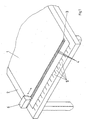
- the printed sheet 1 can be used for visual and measurement purposes Quality control placed on a base 2 become.
- the base 2 is part of a perspective in Figure 1 illustrated measuring desk.
- a measuring strip 3 is also printed on the edge of the printed sheet 1.
- the measuring strip 3 consists of a large number of the measuring fields formed during printing 4.
- the measuring fields 4 result in the measuring strips lying side by side 3 and 5 are the individual ink metering zones 5 in FIG. 1 assigned to the press not shown.
- the ink metering zones 5 are marked on the base 2 (measuring desk) so that the subject located on the printed sheet 1 also with regard to the zonal allocation can be assessed.
- the measuring fields 4 of the color measuring strip 3 point in terms of the individual colors a predetermined order within the Ink metering zones 5. This means, for example, that Measuring field of the color cyan in the individual color metering zones 5 is different in each case. In one color metering zone 5, for example, is the measuring field of the color cyan at the third position, in the next ink metering zone the sixth position, in the next but one ink metering zone 5 again at the second position, etc. For the remaining printing inks and their assignment to the ink metering zones 5 applies appropriate.
- the densitometer measuring head 6 is on a not shown in Figure 1 Suspension articulated and motorized along the direction of extension of the measuring strip can be moved.
- the direction of movement of the densitometer measuring head 6 is in Figure 1 by the double arrow indicated.
- the densitometer measuring head 6 can additionally also a movement perpendicular to the direction of extension of measuring strip 3.
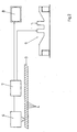
- FIG. 2 shows the densitometer measuring head 6 according to the invention downstream evaluation device 7.
- Densitometer measuring head 6 When scanning the Measuring fields 4 of the measuring strip 3 Densitometer measuring head 6 are designed as computers Evaluation unit 7 supplied to the densitometer measuring head 6 is connected downstream.
- the computer of the evaluation unit 7 is still in shape with a display device 8 of a monitor in operative connection, furthermore the with predefined target values calculated measurement results of the Densitometer measuring head 6 also for setting commands for the Color guidance of a printing press 9 can be used.
- the evaluation unit 7 with the color guide elements (not shown in FIG. 2) of a printing press 9 in Operatively connected.
- the measuring fields 3 one color each of adjacent color metering zones 5.
Landscapes
- Engineering & Computer Science (AREA)
- Quality & Reliability (AREA)
- Inking, Control Or Cleaning Of Printing Machines (AREA)
- Spectrometry And Color Measurement (AREA)
- Printing Methods (AREA)
Claims (2)
- Dispositif pour l'analyse densitométrique de produits imprimés (1), en particulier de feuilles imprimées réalisées dans des machines d'impression offset à feuilles, comportant une tête de mesure densitométrique (6) déplaçable le long d'une bande de mesure (3) de plusieurs champs de mesure (4) d'un type de champ de mesure, dont les signaux peuvent être convertis en valeurs de densité d'encre pouvant être associées à des zones de dosage d'encre (5) dans une unité d'exploitation (7) disposée en aval,
caractérisé en ce que l'unité d'exploitation (7) comporte un calculateur qui mémorise des informations sur l'agencement des champs de mesure (4) des encres imprimées dans les zones de dosage d'encre individuelles (5) et dans lequel les valeurs de densité d'encre d'un champ de mesure (4) peuvent être comparées avec les valeurs de densité d'encre, produites de façon correspondant à la réalisation de la bande de mesure (3), de champs de mesure voisins (4) de la même encre et du même type de champ de mesure, et en ce que, par le calculateur de l'unité d'exploitation (7), pour comparer la valeur de densité d'encre Dn d'un champ de mesure (4) de la zone n avec la valeur de densité d'encre Dn+1 d'un champ de mesure (4) dans une zone voisine n+1, la valeur 4 (Dn+1 - Dn)2 / (Dn+1 + Dn)2 peut être calculée. - Dispositif selon la revendication 1,
caractérisé en ce qu'une identification de la bande de mesure (3) peut être effectuée par le calculateur de l'unité d'exploitation (7) en liaison avec l'association des champs de mesure (4) aux zones de dosage d'encre individuelles (5).
Applications Claiming Priority (2)
| Application Number | Priority Date | Filing Date | Title |
|---|---|---|---|
| DE29916379U | 1999-09-17 | ||
| DE29916379U DE29916379U1 (de) | 1999-09-17 | 1999-09-17 | Vorrichtung zum densitometrischen Ausmessen von Druckprodukten |
Publications (2)
| Publication Number | Publication Date |
|---|---|
| EP1084843A1 EP1084843A1 (fr) | 2001-03-21 |
| EP1084843B1 true EP1084843B1 (fr) | 2003-01-15 |
Family
ID=8079052
Family Applications (1)
| Application Number | Title | Priority Date | Filing Date |
|---|---|---|---|
| EP00117892A Expired - Lifetime EP1084843B1 (fr) | 1999-09-17 | 2000-08-19 | Dispositif pour l'analyse densitométrique de produits imprimés |
Country Status (5)
| Country | Link |
|---|---|
| US (1) | US6446555B1 (fr) |
| EP (1) | EP1084843B1 (fr) |
| JP (1) | JP2001088273A (fr) |
| AT (1) | ATE231072T1 (fr) |
| DE (2) | DE29916379U1 (fr) |
Cited By (1)
| Publication number | Priority date | Publication date | Assignee | Title |
|---|---|---|---|---|
| CN102123868B (zh) * | 2008-08-21 | 2012-11-07 | 柯尼格及包尔公开股份有限公司 | 用于检测至少一个在印刷机中确定的测量值的可信度的方法 |
Families Citing this family (22)
| Publication number | Priority date | Publication date | Assignee | Title |
|---|---|---|---|---|
| ATE552974T1 (de) * | 2001-07-04 | 2012-04-15 | Dainippon Screen Mfg | Vorrichtung und verfahren zum messen des farbmessstreifens |
| JP2003118085A (ja) * | 2001-10-10 | 2003-04-23 | Dainippon Screen Mfg Co Ltd | 印刷装置 |
| JP3880831B2 (ja) * | 2001-10-10 | 2007-02-14 | 大日本スクリーン製造株式会社 | インキプリセット方法 |
| DE60236099D1 (de) * | 2001-10-15 | 2010-06-02 | Toppan Printing Co Ltd | Druckverfahren, druckerzeugnisse und drucksteuerung |
| US6792863B2 (en) * | 2001-10-15 | 2004-09-21 | Dainippon Screen Mfg Co., Ltd. | Printing apparatus for automatically controlling ink supply device |
| JP2003154629A (ja) * | 2001-11-22 | 2003-05-27 | Ryobi Ltd | 両面印刷機の印刷濃度管理装置 |
| JP2003311933A (ja) * | 2002-04-24 | 2003-11-06 | Dainippon Screen Mfg Co Ltd | パッチ測定装置およびそれを組み込んだ印刷装置 |
| JP2003326676A (ja) * | 2002-05-16 | 2003-11-19 | Dainippon Screen Mfg Co Ltd | コントロールストリップ画像データ付加方法およびこのコントロールストリップ画像データ付加方法を用いる画像データ処理装置、製版装置ならびに印刷装置 |
| JP4216001B2 (ja) * | 2002-05-21 | 2009-01-28 | 大日本スクリーン製造株式会社 | 印刷機のインキ供給方法および印刷機のインキ供給装置 |
| JP4279516B2 (ja) * | 2002-07-01 | 2009-06-17 | 大日本スクリーン製造株式会社 | 印刷機 |
| US20040109161A1 (en) * | 2002-12-06 | 2004-06-10 | Stranzl John E. | Method and system for processing color-measurement data |
| JP4072101B2 (ja) | 2003-06-30 | 2008-04-09 | リョービ株式会社 | 両面カラー印刷物におけるカラーバーの認識方法並びにカラー印刷品質管理システム及びカラー印刷品質評価装置 |
| JP4484541B2 (ja) * | 2004-02-20 | 2010-06-16 | 大日本スクリーン製造株式会社 | 印刷機のインキ供給方法 |
| DE102004021601B4 (de) * | 2004-05-03 | 2020-10-22 | Heidelberger Druckmaschinen Ag | Inline-Messung und Regelung bei Druckmaschinen |
| EP2247449B1 (fr) * | 2008-03-01 | 2018-10-31 | Hewlett-Packard Development Company, L.P. | Détection de colorants dans un liquide support |
| DE102008041429B4 (de) * | 2008-08-21 | 2013-09-12 | Koenig & Bauer Aktiengesellschaft | Verfahren zur Prüfung zumindest eines in einem laufenden Druckprozess einer Druckmaschine ermittelten Messwertes auf seine Plausibilität |
| DE102008041426B4 (de) * | 2008-08-21 | 2014-09-04 | Koenig & Bauer Aktiengesellschaft | Verfahren zur Verwendung in einer Druckmaschine mit mindestens einem Farbwerk |
| DE102008041430B4 (de) | 2008-08-21 | 2011-12-08 | Koenig & Bauer Aktiengesellschaft | Verfahren zur Prüfung zumindest eines in einem laufenden Druckprozess einer Druckmaschine ermittelten Messwertes auf seine Plausibilität |
| US8683922B2 (en) * | 2012-06-12 | 2014-04-01 | Goss International Americas, Inc. | Closed loop ink control system for a printing press |
| DE102013109920A1 (de) * | 2013-09-10 | 2015-03-12 | Manroland Web Systems Gmbh | Verfahren zum Bedrucken eines Bedruckstoffs |
| US10647131B2 (en) | 2016-06-22 | 2020-05-12 | Hewlett-Packard Development Company, L.P. | Density modulated auto-duplexing |
| DE102021120841A1 (de) | 2021-08-11 | 2023-02-16 | Koenig & Bauer Ag | Verfahren zur Farbregelung in einer Druckmaschine |
Family Cites Families (21)
| Publication number | Priority date | Publication date | Assignee | Title |
|---|---|---|---|---|
| DE2728738B2 (de) * | 1977-06-25 | 1979-05-10 | Roland Offsetmaschinenfabrik Faber & Schleicher Ag, 6050 Offenbach | Eulrichtung zur Kontrolle und Regelung der Farbgebung an Druckmaschinen |
| ATE15271T1 (de) * | 1981-04-03 | 1985-09-15 | Gretag Ag | Verfahren und vorrichtung zur farbmetrischen analyse eines gedruckten farbmessstreifens. |
| DE3136705C1 (de) * | 1981-09-16 | 1982-10-28 | M.A.N.- Roland Druckmaschinen AG, 6050 Offenbach | Verfahren zur Herstellung passgenauer Drucke in Druckmaschinen |
| DE3331208A1 (de) * | 1983-08-30 | 1985-03-14 | M.A.N.- Roland Druckmaschinen AG, 6050 Offenbach | Verfahren zum einstellen des farbwerks einer druckmaschine und messvorrichtung zu seiner durchfuehrung |
| DE3465930D1 (en) * | 1983-11-04 | 1987-10-15 | Gretag Ag | Method and device for controlling the ink supply in an offset printing machine, and offset printing machine provided with such a device |
| US5182721A (en) * | 1985-12-10 | 1993-01-26 | Heidelberger Druckmaschinen Aktiengesellschaft | Process and apparatus for controlling the inking process in a printing machine |
| JP2657914B2 (ja) * | 1986-12-08 | 1997-09-30 | 株式会社 小森コーポレーション | 走査濃度計の測定位置同期方法 |
| DE3643721A1 (de) * | 1986-12-20 | 1988-06-30 | Heidelberger Druckmasch Ag | Druckkontrollstreifen |
| DE3643720C2 (de) * | 1986-12-20 | 1994-03-10 | Heidelberger Druckmasch Ag | Verfahren zum Ermitteln von Steuer- /Regelgrößen für das Farbwerk von Druckmaschinen |
| DE58901780D1 (de) * | 1988-01-14 | 1992-08-13 | Gretag Ag | Verfahren und vorrichtung zur farbregelung einer druckmaschine. |
| DE3855538T2 (de) * | 1988-11-23 | 1997-01-23 | Komori Printing Mach | Verfahren zum Auswerten des Farbmessstreifens bei selbsttätiger densitometrischer Farbsteuerung |
| DE3942254A1 (de) * | 1989-12-21 | 1991-07-04 | Krzyminski Harald | Druckkontrollstreifen |
| US5224421A (en) * | 1992-04-28 | 1993-07-06 | Heidelberg Harris, Inc. | Method for color adjustment and control in a printing press |
| DE4240077C2 (de) * | 1992-11-28 | 1997-01-16 | Heidelberger Druckmasch Ag | Verfahren zur zonalen Steuerung/Regelung der Farbführung in einer Druckmaschine |
| US5357448A (en) * | 1993-02-02 | 1994-10-18 | Quad/Tech, Inc. | Method and apparatus for controlling the printing of an image having a plurality of printed colors |
| DE4321179A1 (de) * | 1993-06-25 | 1995-01-05 | Heidelberger Druckmasch Ag | Verfahren und Einrichtung zur Steuerung oder Regelung von Betriebsvorgängen einer drucktechnischen Maschine |
| JPH09507040A (ja) * | 1993-10-28 | 1997-07-15 | ペレッタ グラフィクス コーポレーション | インク濃度を保持するためのシステム |
| US6058201A (en) * | 1995-05-04 | 2000-05-02 | Web Printing Controls Co., Inc. | Dynamic reflective density measuring and control system for a web printing press |
| US6318260B1 (en) * | 1997-05-05 | 2001-11-20 | Quad/Tech, Inc. | Ink key control in a printing press including lateral ink spread, ink saturation, and back-flow compensation |
| US5967050A (en) * | 1998-10-02 | 1999-10-19 | Quad/Tech, Inc. | Markless color control in a printing press |
| US6142078A (en) * | 1998-11-10 | 2000-11-07 | Quad/Tech, Inc. | Adaptive color control system and method for regulating ink utilizing a gain parameter and sensitivity adapter |
-
1999
- 1999-09-17 DE DE29916379U patent/DE29916379U1/de not_active Expired - Lifetime
-
2000
- 2000-08-19 EP EP00117892A patent/EP1084843B1/fr not_active Expired - Lifetime
- 2000-08-19 AT AT00117892T patent/ATE231072T1/de active
- 2000-08-19 DE DE50001077T patent/DE50001077D1/de not_active Expired - Lifetime
- 2000-09-15 US US09/662,916 patent/US6446555B1/en not_active Expired - Fee Related
- 2000-09-18 JP JP2000282516A patent/JP2001088273A/ja active Pending
Cited By (1)
| Publication number | Priority date | Publication date | Assignee | Title |
|---|---|---|---|---|
| CN102123868B (zh) * | 2008-08-21 | 2012-11-07 | 柯尼格及包尔公开股份有限公司 | 用于检测至少一个在印刷机中确定的测量值的可信度的方法 |
Also Published As
| Publication number | Publication date |
|---|---|
| EP1084843A1 (fr) | 2001-03-21 |
| US6446555B1 (en) | 2002-09-10 |
| ATE231072T1 (de) | 2003-02-15 |
| JP2001088273A (ja) | 2001-04-03 |
| DE29916379U1 (de) | 1999-12-09 |
| DE50001077D1 (de) | 2003-02-20 |
Similar Documents
| Publication | Publication Date | Title |
|---|---|---|
| EP1084843A1 (fr) | Dispositif pour l'analyse densitométrique de produits imprimés | |
| EP0142470B1 (fr) | Procédé et dispositif d'analyse de la qualité d'impression d'un imprimé, de préférence imprimé sur une rotative offset et rotative offset équipée d'un tel dispositif | |
| DE4431270C2 (de) | Verfahren zur Steuerung der Farbführung einer autotypisch arbeitenden Druckmaschine | |
| DE3643720A1 (de) | Verfahren zum ermitteln von steuer- /regelgroessen fuer das farbwerk von druckmaschinen | |
| EP0659559B1 (fr) | Méthode pour contrÔler l'apport d'encre dans une machine d'impression | |
| DE19749066A1 (de) | Verfahren zur Regelung des Farbauftrages bei einer Druckmaschine | |
| EP0836941B1 (fr) | Groupe de champs de mesure et procédé pour la saisie des données de qualité dans les éditions (tirages) d'impression polychrome | |
| EP0585740B1 (fr) | Méthode pour la commande du processus d'impression dans une presse d'imprimerie à cliché trame en particulier une machine à imprimer offset à feuilles | |
| DE102012004482A1 (de) | Nutzenfarboptimierung | |
| DE3219743C2 (de) | Verfahren zur farbmetrischen Auswertung eines auf der Schöndruck- und auf der Widerdruckseite in einem Maschinendurchgang bedruckten Bogens | |
| DE102010051952B4 (de) | Analyse Farbauszüge | |
| DE4237004A1 (de) | Verfahren zur Online-Farbregelung von Druckmaschinen | |
| DE102020129871B4 (de) | Verfahren zum Einrichten einer Tintenstrahldruckmaschine mit Anpassung von Druckansteuerdaten durch eine Modifikationsfunktion | |
| EP0590282B1 (fr) | Barres de contrÔle pour commander et surveiller le processus d'impression | |
| EP0916491B1 (fr) | Procédé pour déterminer des gradients colorimétriques | |
| DE4038574C2 (de) | Verfahren zur Steuerung des Druckfarbenauftrages bei der Herstellung von mehrfarbigen Druckerzeugnissen | |
| DE102008056170B4 (de) | Farbmessgerät mit automatischer Seitenerkennung | |
| DE3855538T2 (de) | Verfahren zum Auswerten des Farbmessstreifens bei selbsttätiger densitometrischer Farbsteuerung | |
| DE102005060893B4 (de) | Verfahren zur Ermittlung eines drucktechnischen Messwertes | |
| DE3942254C2 (fr) | ||
| DE3440706C2 (fr) | ||
| DE102022108751A1 (de) | Verfahren zum Betreiben einer Tintenstrahldruckmaschine zum Erzeugen reproduzierbarer Druckergebnisse | |
| DE102004044763B4 (de) | Messfeldanordnung | |
| EP0734862B1 (fr) | Procédé pour détecter des impuretés de couleur | |
| DE19845915A1 (de) | Verfahren und Vorrichtung zur Farbzufuhrsteuerung |
Legal Events
| Date | Code | Title | Description |
|---|---|---|---|
| PUAI | Public reference made under article 153(3) epc to a published international application that has entered the european phase |
Free format text: ORIGINAL CODE: 0009012 |
|
| AK | Designated contracting states |
Kind code of ref document: A1 Designated state(s): AT BE CH CY DE DK ES FI FR GB GR IE IT LI LU MC NL PT SE |
|
| AX | Request for extension of the european patent |
Free format text: AL;LT;LV;MK;RO;SI |
|
| 17P | Request for examination filed |
Effective date: 20010201 |
|
| 17Q | First examination report despatched |
Effective date: 20011030 |
|
| AKX | Designation fees paid |
Free format text: AT BE CH CY DE DK ES FI FR GB GR IE IT LI LU MC NL PT SE |
|
| GRAH | Despatch of communication of intention to grant a patent |
Free format text: ORIGINAL CODE: EPIDOS IGRA |
|
| GRAH | Despatch of communication of intention to grant a patent |
Free format text: ORIGINAL CODE: EPIDOS IGRA |
|
| GRAA | (expected) grant |
Free format text: ORIGINAL CODE: 0009210 |
|
| AK | Designated contracting states |
Kind code of ref document: B1 Designated state(s): AT BE CH CY DE DK ES FI FR GB GR IE IT LI LU MC NL PT SE |
|
| PG25 | Lapsed in a contracting state [announced via postgrant information from national office to epo] |
Ref country code: GR Free format text: LAPSE BECAUSE OF FAILURE TO SUBMIT A TRANSLATION OF THE DESCRIPTION OR TO PAY THE FEE WITHIN THE PRESCRIBED TIME-LIMIT Effective date: 20030115 Ref country code: IE Free format text: LAPSE BECAUSE OF FAILURE TO SUBMIT A TRANSLATION OF THE DESCRIPTION OR TO PAY THE FEE WITHIN THE PRESCRIBED TIME-LIMIT Effective date: 20030115 Ref country code: FI Free format text: LAPSE BECAUSE OF FAILURE TO SUBMIT A TRANSLATION OF THE DESCRIPTION OR TO PAY THE FEE WITHIN THE PRESCRIBED TIME-LIMIT Effective date: 20030115 |
|
| REG | Reference to a national code |
Ref country code: GB Ref legal event code: FG4D Free format text: NOT ENGLISH Ref country code: CH Ref legal event code: EP |
|
| REG | Reference to a national code |
Ref country code: CH Ref legal event code: NV Representative=s name: E. BLUM & CO. PATENTANWAELTE |
|
| GBT | Gb: translation of ep patent filed (gb section 77(6)(a)/1977) |
Effective date: 20030115 |
|
| REG | Reference to a national code |
Ref country code: IE Ref legal event code: FG4D Free format text: GERMAN |
|
| REF | Corresponds to: |
Ref document number: 50001077 Country of ref document: DE Date of ref document: 20030220 Kind code of ref document: P |
|
| PG25 | Lapsed in a contracting state [announced via postgrant information from national office to epo] |
Ref country code: DK Free format text: LAPSE BECAUSE OF FAILURE TO SUBMIT A TRANSLATION OF THE DESCRIPTION OR TO PAY THE FEE WITHIN THE PRESCRIBED TIME-LIMIT Effective date: 20030415 Ref country code: PT Free format text: LAPSE BECAUSE OF FAILURE TO SUBMIT A TRANSLATION OF THE DESCRIPTION OR TO PAY THE FEE WITHIN THE PRESCRIBED TIME-LIMIT Effective date: 20030415 |
|
| REG | Reference to a national code |
Ref country code: SE Ref legal event code: TRGR |
|
| ET | Fr: translation filed | ||
| PG25 | Lapsed in a contracting state [announced via postgrant information from national office to epo] |
Ref country code: ES Free format text: LAPSE BECAUSE OF FAILURE TO SUBMIT A TRANSLATION OF THE DESCRIPTION OR TO PAY THE FEE WITHIN THE PRESCRIBED TIME-LIMIT Effective date: 20030730 |
|
| PG25 | Lapsed in a contracting state [announced via postgrant information from national office to epo] |
Ref country code: CY Free format text: LAPSE BECAUSE OF FAILURE TO SUBMIT A TRANSLATION OF THE DESCRIPTION OR TO PAY THE FEE WITHIN THE PRESCRIBED TIME-LIMIT Effective date: 20030819 Ref country code: LU Free format text: LAPSE BECAUSE OF NON-PAYMENT OF DUE FEES Effective date: 20030819 |
|
| REG | Reference to a national code |
Ref country code: IE Ref legal event code: FD4D Ref document number: 1084843E Country of ref document: IE |
|
| PG25 | Lapsed in a contracting state [announced via postgrant information from national office to epo] |
Ref country code: MC Free format text: LAPSE BECAUSE OF NON-PAYMENT OF DUE FEES Effective date: 20030831 |
|
| PLBE | No opposition filed within time limit |
Free format text: ORIGINAL CODE: 0009261 |
|
| STAA | Information on the status of an ep patent application or granted ep patent |
Free format text: STATUS: NO OPPOSITION FILED WITHIN TIME LIMIT |
|
| 26N | No opposition filed |
Effective date: 20031016 |
|
| REG | Reference to a national code |
Ref country code: CH Ref legal event code: PFA Owner name: MAN ROLAND DRUCKMASCHINEN AG Free format text: MAN ROLAND DRUCKMASCHINEN AG#MUEHLHEIMER STRASSE 341#63075 OFFENBACH (DE) -TRANSFER TO- MAN ROLAND DRUCKMASCHINEN AG#MUEHLHEIMER STRASSE 341#63075 OFFENBACH (DE) |
|
| REG | Reference to a national code |
Ref country code: CH Ref legal event code: PFA Owner name: MANROLAND AG Free format text: MAN ROLAND DRUCKMASCHINEN AG#MUEHLHEIMER STRASSE 341#63075 OFFENBACH (DE) -TRANSFER TO- MANROLAND AG#MUEHLHEIMER STRASSE 341#63075 OFFENBACH (DE) |
|
| NLT1 | Nl: modifications of names registered in virtue of documents presented to the patent office pursuant to art. 16 a, paragraph 1 |
Owner name: MANROLAND AG |
|
| REG | Reference to a national code |
Ref country code: FR Ref legal event code: CD |
|
| PGFP | Annual fee paid to national office [announced via postgrant information from national office to epo] |
Ref country code: NL Payment date: 20100813 Year of fee payment: 11 |
|
| PGFP | Annual fee paid to national office [announced via postgrant information from national office to epo] |
Ref country code: AT Payment date: 20100812 Year of fee payment: 11 Ref country code: SE Payment date: 20100812 Year of fee payment: 11 Ref country code: IT Payment date: 20100823 Year of fee payment: 11 Ref country code: FR Payment date: 20100901 Year of fee payment: 11 |
|
| PGFP | Annual fee paid to national office [announced via postgrant information from national office to epo] |
Ref country code: GB Payment date: 20100819 Year of fee payment: 11 |
|
| PGFP | Annual fee paid to national office [announced via postgrant information from national office to epo] |
Ref country code: BE Payment date: 20100810 Year of fee payment: 11 |
|
| PGFP | Annual fee paid to national office [announced via postgrant information from national office to epo] |
Ref country code: CH Payment date: 20110824 Year of fee payment: 12 |
|
| PGFP | Annual fee paid to national office [announced via postgrant information from national office to epo] |
Ref country code: DE Payment date: 20110823 Year of fee payment: 12 |
|
| BERE | Be: lapsed |
Owner name: MANROLAND A.G. Effective date: 20110831 |
|
| REG | Reference to a national code |
Ref country code: NL Ref legal event code: V1 Effective date: 20120301 |
|
| REG | Reference to a national code |
Ref country code: SE Ref legal event code: EUG |
|
| GBPC | Gb: european patent ceased through non-payment of renewal fee |
Effective date: 20110819 |
|
| REG | Reference to a national code |
Ref country code: FR Ref legal event code: ST Effective date: 20120430 |
|
| PG25 | Lapsed in a contracting state [announced via postgrant information from national office to epo] |
Ref country code: IT Free format text: LAPSE BECAUSE OF NON-PAYMENT OF DUE FEES Effective date: 20110819 Ref country code: BE Free format text: LAPSE BECAUSE OF NON-PAYMENT OF DUE FEES Effective date: 20110831 Ref country code: NL Free format text: LAPSE BECAUSE OF NON-PAYMENT OF DUE FEES Effective date: 20120301 |
|
| REG | Reference to a national code |
Ref country code: DE Ref legal event code: R081 Ref document number: 50001077 Country of ref document: DE Owner name: MANROLAND SHEETFED GMBH, DE Free format text: FORMER OWNER: MANROLAND AG, 63075 OFFENBACH, DE Effective date: 20120509 |
|
| PG25 | Lapsed in a contracting state [announced via postgrant information from national office to epo] |
Ref country code: GB Free format text: LAPSE BECAUSE OF NON-PAYMENT OF DUE FEES Effective date: 20110819 Ref country code: FR Free format text: LAPSE BECAUSE OF NON-PAYMENT OF DUE FEES Effective date: 20110831 |
|
| REG | Reference to a national code |
Ref country code: AT Ref legal event code: MM01 Ref document number: 231072 Country of ref document: AT Kind code of ref document: T Effective date: 20110819 |
|
| PG25 | Lapsed in a contracting state [announced via postgrant information from national office to epo] |
Ref country code: AT Free format text: LAPSE BECAUSE OF NON-PAYMENT OF DUE FEES Effective date: 20110819 |
|
| REG | Reference to a national code |
Ref country code: CH Ref legal event code: PL |
|
| PG25 | Lapsed in a contracting state [announced via postgrant information from national office to epo] |
Ref country code: SE Free format text: LAPSE BECAUSE OF NON-PAYMENT OF DUE FEES Effective date: 20110820 Ref country code: LI Free format text: LAPSE BECAUSE OF NON-PAYMENT OF DUE FEES Effective date: 20120831 Ref country code: CH Free format text: LAPSE BECAUSE OF NON-PAYMENT OF DUE FEES Effective date: 20120831 |
|
| PG25 | Lapsed in a contracting state [announced via postgrant information from national office to epo] |
Ref country code: DE Free format text: LAPSE BECAUSE OF NON-PAYMENT OF DUE FEES Effective date: 20130301 |
|
| REG | Reference to a national code |
Ref country code: DE Ref legal event code: R119 Ref document number: 50001077 Country of ref document: DE Effective date: 20130301 |