EP1084846B1 - Druckkopf für einen Tintenstrahldrucker - Google Patents
Druckkopf für einen Tintenstrahldrucker Download PDFInfo
- Publication number
- EP1084846B1 EP1084846B1 EP00203071A EP00203071A EP1084846B1 EP 1084846 B1 EP1084846 B1 EP 1084846B1 EP 00203071 A EP00203071 A EP 00203071A EP 00203071 A EP00203071 A EP 00203071A EP 1084846 B1 EP1084846 B1 EP 1084846B1
- Authority
- EP
- European Patent Office
- Prior art keywords
- nozzle
- print head
- reserve
- sub
- regular
- Prior art date
- Legal status (The legal status is an assumption and is not a legal conclusion. Google has not performed a legal analysis and makes no representation as to the accuracy of the status listed.)
- Expired - Lifetime
Links
- 230000002950 deficient Effects 0.000 claims description 27
- 238000000034 method Methods 0.000 claims description 17
- 239000011295 pitch Substances 0.000 description 18
- 238000010586 diagram Methods 0.000 description 5
- 239000007787 solid Substances 0.000 description 3
- 230000015556 catabolic process Effects 0.000 description 1
- 238000010276 construction Methods 0.000 description 1
- 238000006073 displacement reaction Methods 0.000 description 1
Images

Classifications
-
- B—PERFORMING OPERATIONS; TRANSPORTING
- B41—PRINTING; LINING MACHINES; TYPEWRITERS; STAMPS
- B41J—TYPEWRITERS; SELECTIVE PRINTING MECHANISMS, i.e. MECHANISMS PRINTING OTHERWISE THAN FROM A FORME; CORRECTION OF TYPOGRAPHICAL ERRORS
- B41J2/00—Typewriters or selective printing mechanisms characterised by the printing or marking process for which they are designed
- B41J2/005—Typewriters or selective printing mechanisms characterised by the printing or marking process for which they are designed characterised by bringing liquid or particles selectively into contact with a printing material
- B41J2/01—Ink jet
- B41J2/21—Ink jet for multi-colour printing
- B41J2/2132—Print quality control characterised by dot disposition, e.g. for reducing white stripes or banding
- B41J2/2139—Compensation for malfunctioning nozzles creating dot place or dot size errors
-
- B—PERFORMING OPERATIONS; TRANSPORTING
- B41—PRINTING; LINING MACHINES; TYPEWRITERS; STAMPS
- B41J—TYPEWRITERS; SELECTIVE PRINTING MECHANISMS, i.e. MECHANISMS PRINTING OTHERWISE THAN FROM A FORME; CORRECTION OF TYPOGRAPHICAL ERRORS
- B41J2/00—Typewriters or selective printing mechanisms characterised by the printing or marking process for which they are designed
- B41J2/485—Typewriters or selective printing mechanisms characterised by the printing or marking process for which they are designed characterised by the process of building-up characters or image elements applicable to two or more kinds of printing or marking processes
- B41J2/505—Typewriters or selective printing mechanisms characterised by the printing or marking process for which they are designed characterised by the process of building-up characters or image elements applicable to two or more kinds of printing or marking processes from an assembly of identical printing elements
- B41J2/5056—Typewriters or selective printing mechanisms characterised by the printing or marking process for which they are designed characterised by the process of building-up characters or image elements applicable to two or more kinds of printing or marking processes from an assembly of identical printing elements using dot arrays providing selective dot disposition modes, e.g. different dot densities for high speed and high-quality printing, array line selections for multi-pass printing, or dot shifts for character inclination
Definitions
- the invention also relates to a method of printing an image built up from a number of sub-images.
- a print head of this kind is known from EP-A-0 783 973.
- the distance between the reserve nozzle and the end is also a multiple of the regular nozzle pitch.
- the print head is moved from a starting position over an "outgoing pass" and thus an image is printed by properly operating regular nozzles.
- the nozzle which is not operative is recorded.
- the print head is then displaced over one or more nozzle pitches in a direction perpendicular to the outgoing pass so that a properly operating nozzle comes into the position of a non-printed line due to a defective nozzle.
- the non-printed line from the "outgoing" pass is then printed during the movement of the print head in the opposite direction to the outgoing pass, the "return” pass, with the associated properly operating regular nozzle.
- the other nozzles are not activated on this return pass.
- the print head is moved back in a direction perpendicular to the outgoing pass into the original starting position and the print head is moved up over a "swath" length, i.e. over the complete length of the row of regular nozzles, in a direction perpendicular to the outgoing and return pass into a new starting position.
- Print heads are also known with an interlacing pass n>1, for example from US-A-5640183.
- a print head of the type described above is characterised according to the invention in that the number of interlacing passes required, n, is larger than 1 (n>1) and the distance between the reserve nozzle and the associated end of the row is l*ds, where I is an integer and is not equal to (p/k)*n , where p is an integer, and k is an integer smaller than n. Since interlacing is effected, an image is built up from different sub-images, the number of sub-images being equal to n. When the distance satisfies this condition, the reserve nozzle is not situated at a distance of a multiple of the regular nozzle pitch from the end. Consequently, on displacement of the reserve nozzle to a position of a missing line, in order to fill in the line in a following pass, this avoids regular nozzles being disposed in a following pass at locations of lines which have already been filled in.
- the loss of productivity is further limited by disposing a reserve nozzle at both ends.
- the latter is provided with a plurality of reserve nozzles at one end.
- the invention further applies to a method of printing an image built up from a number of sub-images, wherein neighbouring sub-images are spaced apart by a dot pitch ds, in which method a print head is used in accordance with the invention, said method comprising the steps of:
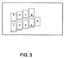
- a first series of four sub-images is first printed.
- the print head then shifts over a print head length and a second series of four sub-images is printed.
- the two blank lines finally remaining in these conditions due to the defective nozzle are printed in the extra pass, sub-image No. 9.
- This method is for use on print heads with an arbitrary interlacing pass n, by performing the extra pass after the nth printing pass, only the first and second reserve nozzles printing in this case.
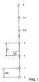
- Fig. 1 is a diagram showing a print head with x regular nozzles and a reserve nozzle.
- Fig. 2 is a diagram showing a print head with x regular nozzles and a reserve nozzle at both ends.
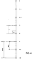
- Fig. 4 is a diagram showing a print head with x regular nozzles with a plurality of reserve nozzles at one end.
- Fig. 1 shows the print head for an inkjet printer according to the invention.
- the distance between adjacent regular nozzles, i.e. the nozzle pitch, is denoted by N.
- the distance over which the print head is displaced in the printing of consecutive sub-images, i.e. the dot pitch, is denoted by ds.
- the number of sub-images from which an image is built up is termed the interlacing pass, and according to the invention it is an integer greater than 1.
- the following relationship exists between the nozzle pitch, the dot pitch and the interlacing pass: n N/ds.
- a print head comprises x regular nozzles. Printing takes place with these regular nozzles.
- the number of x regular nozzles is, for example: 128, 256 or 512.
- the invention will be explained hereinafter by reference to an example with four interlacing passes. However, it will be clear that the invention can also be applied to any other number of interlacing passes greater than 1.
- interlacing printing is effected by building up the image from a number of sub-images, neighbouring sub-images being spaced apart by the dot pitch ds. This is done as follows: first of all the first sub-image is printed by the regular nozzles. The print head is then moved up perpendicularly to the printing direction over a dot pitch ds and a second sub-image is printed by the regular nozzles.
- the print head is then again moved up over a dot pitch ds and the third sub-image is printed.
- the printing of sub-images takes place four times in all.
- the print head is then displaced over a print head length, perpendicularly to the printing direction, and repeats the printing of the four sub-images followed by the moving of the print head up over a print head length.
- N 40 ⁇ m
- ds 10 ⁇ m
- the second sub-image is then printed, in which case both the properly operating regular nozzles and the reserve nozzle E print.
- the white line due to the defective nozzle 3 of the first sub-image printing is now effected by the reserve nozzle E while the regular nozzles print lines on positions which have not yet been printed.
- a second sub-image is printed in this way.
- a white line will also form in this second sub-image as a result of the defective nozzle 3.
- This line can again be printed by moving the print head up over a distance such that the reserve nozzle E comes to rest in the position of the white line in the second sub-image due to the defective nozzle 3.
- the inventive method should be used independently of the location of the defective regular nozzle. If the defective nozzle is far away from the reserve nozzle, then in the first instance an unsharp image will form because the print head is displaced over a relatively large distance between two sub-images. If, for example, a regular nozzle breaks down at the other end from where the reserve nozzle is situated, then the print head will still be displaced over substantially one print head distance during the printing of consecutive sub-images. This results in an unsharp image. This phenomenon, however, can be eliminated by so programming the print head that the missing lines due to the movement of the print head are filled in prior to or following on the printing of the sub-images. In this way and with this print head a print of acceptable quality is obtained in efficient manner.
- 3*ds can be selected, for example, for the distance from the reserve nozzle to the end of the row of regular nozzles. According to the equation for determining this distance, 1*ds would also be admissible, but this distance can be obtained only with considerable difficulty in view of the small distance of 10 ⁇ m in this exemplified embodiment. A distance of 3*ds (30 m ⁇ ) is easier to embody in practice.
- Fig. 2 shows a print head according to the invention with a reserve nozzle E1, E2 at both ends of the row of regular nozzles, respectively formed by regular nozzle 1 and x.
- the distance between the reserve nozzles E1, E2 is so selected that the two missing lines left after printing the eight sub-images and resulting from a defective nozzle can be filled in in one extra pass, as will be explained hereinafter.
- the first sub-image is printed with properly operating regular nozzles (pass 1).
- the white line due to the defective nozzle is shown as a solid black line in the first sub-image.
- the print head is then moved up over a distance such that the first reserve nozzle E1 fills in the missing line due to the defective nozzle; in this case the properly operating regular nozzles simultaneously print the second sub-image (pass 2).
- the white line forming as a result of the defective nozzle in this second sub-image is again shown as a solid black line.
- the first reserve nozzle E1 has now printed at the location of the white line due to the defective nozzle, which formed during the printing of the first sub-image; the solid black line in Fig.
- the print head is then moved up over a print head length and again four sub-images are printed (passes 5 to 8 inclusive) in accordance with the above-described method.
- the eighth sub-image belonging to pass 8 will still have a white line.
- Fig. 4 shows an alternative embodiment of a print head according to the invention with a number of reserve nozzles at one end.
- pass 9 can then be filled in, for example, by reserve nozzle E2 and regular nozzle x-1.
- the invention is effective irrespective of the number of nozzles of the print head and the location of the defective nozzle.
- the distance from the reserve nozzle to the associated end should satisfy the inventive relationship, and it will be clear that in order to keep the print head compact the distance is preferably made as small as possible in practice.
- the invention is not limited to a print head with one row of regular nozzles, but can also be applied to a print head having a plurality of rows of regular nozzles.
Landscapes
- Engineering & Computer Science (AREA)
- Quality & Reliability (AREA)
- Ink Jet (AREA)
- Particle Formation And Scattering Control In Inkjet Printers (AREA)
Claims (6)
- Druckkopf für einen Tintenstrahldrucker mit n verschachtelten Passagen, mit n > 1, welcher Druckkopf eine Anzahl von in einer Reihe angeordneten regulären Düsen aufweist, wobei die Reihe ein erstes und ein zweites Ende hat, die jeweils durch eine zugehörige reguläre Düse gebildet werden, und benachbarte reguläre Düsen in einem regulären Düsenabstand N zueinander angeordnet sind, wobei N = n*ds, wobei ds der Punktabstand ist, und wobei eine Reservedüse in einem Abstand zu wenigstens einem der Enden der Reihe und in Verlängerung der Reihe angeordnet ist, dadurch gekennzeichnet, daß der Abstand zwischen der Reservedüse und dem zugehörigen Ende der Reihe l*ds ist, wobei l eine ganze Zahl ungleich (p/k)*n ist, p eine ganze Zahl ist und k eine ganze Zahl kleiner als n ist.
- Druckkopf-nach Anspruch 1, dadurch gekennzeichnet, daß eine Reserve düse an beiden Enden angeordnet ist.
- Druckkopf nach Anspruch 1, dadurch gekennzeichnet, daß mehrere Reservedüsen an einem Ende angeordnet sind.
- Druckkopf nach Anspruch 1, dadurch gekennzeichnet, daß n = 4 und l ungerade ist.
- Verfahren zum Drucken eines Bildes, das aus einer Anzahl von Teilbildern aufgebaut ist, wobei benachbarte Teilbilder um einen Punktabstand ds zueinander beabstandet sind, mit den folgenden Schritten:bereitstellen eines Druckkopfes nach einem der vorstehenden Ansprüche 1-4,ausführen einer Anzahl von Druckpassagen des Druckkopfes, um die Anzahl von Teilbildern zu bilden,detektieren der Position einer schadhaften regulären Düse vor bzw. während einer ersten Druckpassage undverschieben des Druckkopfes zwischen einer vorhergehenden und einer nachfolgenden Druckpassage um einen solchen Abstand, daß die Reservedüse während der nachfolgenden Druckpassage in die Position gelangt, in der sich in der vorhergehenden Druckpassage die schadhafte Düse befunden hat.
- Verfahren nach Anspruch 5, bei dem ein Gitter aus acht Teilbildern hergestellt wird, dadurch gekennzeichnet, daß eine erste Reservedüse und eine zweite Reservedüse verwendet werden und daß eine zusätzliche Passage, Teilbild Nr. 9, gemacht wird, während der beide Reservedüsen simultan in solcher Weise drucken, daß keine durch eine schadhafte Düse verursachte leere Zeile mehr in dem Gitter verbleibt.
Applications Claiming Priority (2)
| Application Number | Priority Date | Filing Date | Title |
|---|---|---|---|
| NL1013063A NL1013063C2 (nl) | 1999-09-16 | 1999-09-16 | Printkop voor een inkjet printer. |
| NL1013063 | 1999-09-16 |
Publications (2)
| Publication Number | Publication Date |
|---|---|
| EP1084846A1 EP1084846A1 (de) | 2001-03-21 |
| EP1084846B1 true EP1084846B1 (de) | 2005-12-28 |
Family
ID=19769884
Family Applications (1)
| Application Number | Title | Priority Date | Filing Date |
|---|---|---|---|
| EP00203071A Expired - Lifetime EP1084846B1 (de) | 1999-09-16 | 2000-09-06 | Druckkopf für einen Tintenstrahldrucker |
Country Status (5)
| Country | Link |
|---|---|
| US (1) | US6450613B1 (de) |
| EP (1) | EP1084846B1 (de) |
| JP (1) | JP4397112B2 (de) |
| DE (1) | DE60025100T2 (de) |
| NL (1) | NL1013063C2 (de) |
Families Citing this family (13)
| Publication number | Priority date | Publication date | Assignee | Title |
|---|---|---|---|---|
| DE60140323D1 (de) * | 2001-10-31 | 2009-12-10 | Agfa Graphics Nv | Verfahren und Gerät zur Aufrechterhaltung der Farbenreihenfolge während des Druckens |
| DE60116327T2 (de) * | 2001-10-31 | 2006-08-03 | Agfa-Gevaert | Druckverfahren und Druckgerät zum gegenseitigen interstitiellen und wahlweisen verketteten Drucken |
| US6682172B2 (en) | 2001-10-31 | 2004-01-27 | Agfa-Gevaert | Method and apparatus for maintaining colour sequence when printing |
| US7025437B2 (en) | 2001-10-31 | 2006-04-11 | Agfa-Gevaert | Printing methods and apparatus for mutually interstitial printing and optional interlacing |
| EP1621353B1 (de) * | 2001-10-31 | 2009-10-28 | Agfa Graphics N.V. | Verfahren und Gerät zur Aufrechterhaltung der Farbenreihenfolge während des Druckens |
| JP4010889B2 (ja) * | 2002-07-01 | 2007-11-21 | 富士フイルム株式会社 | 記録ヘッドおよび画像記録方法ならびに画像記録装置 |
| JP4227489B2 (ja) * | 2003-09-03 | 2009-02-18 | キヤノン株式会社 | 記録装置及び記録方法 |
| JP4262165B2 (ja) * | 2003-09-03 | 2009-05-13 | キヤノン株式会社 | 記録装置及びデータ処理方法 |
| CN100363800C (zh) * | 2003-12-29 | 2008-01-23 | 财团法人工业技术研究院 | 以喷墨打印修补元件的方法 |
| US7543903B2 (en) * | 2004-05-26 | 2009-06-09 | Hewlett-Packard Development Company, L.P. | Image-forming device diagnosis |
| KR20070008226A (ko) * | 2005-07-13 | 2007-01-17 | 삼성전자주식회사 | 잉크젯 화상형성장치 및 잉크젯 화상형성장치의 고해상도인쇄 방법 |
| JP6607043B2 (ja) * | 2016-01-05 | 2019-11-20 | セイコーエプソン株式会社 | 液体吐出装置、液体吐出方法 |
| US11260652B2 (en) | 2017-01-27 | 2022-03-01 | Hewlett-Packard Development Company, L.P. | Print head nozzle spitting |
Family Cites Families (9)
| Publication number | Priority date | Publication date | Assignee | Title |
|---|---|---|---|---|
| US5124720A (en) * | 1990-08-01 | 1992-06-23 | Hewlett-Packard Company | Fault-tolerant dot-matrix printing |
| US5640183A (en) * | 1994-07-20 | 1997-06-17 | Hewlett-Packard Company | Redundant nozzle dot matrix printheads and method of use |
| JP3606403B2 (ja) * | 1995-04-27 | 2005-01-05 | セイコーエプソン株式会社 | 印刷装置および印刷方法 |
| JP3175539B2 (ja) * | 1995-06-21 | 2001-06-11 | 富士ゼロックス株式会社 | 記録装置および印字制御方法 |
| JP3359211B2 (ja) | 1995-12-28 | 2002-12-24 | キヤノン株式会社 | 記録方法および記録装置 |
| JP3486906B2 (ja) * | 1996-06-19 | 2004-01-13 | セイコーエプソン株式会社 | インクジェットプリンタ |
| JP3595663B2 (ja) * | 1996-10-30 | 2004-12-02 | キヤノン株式会社 | インクジェット記録装置およびインクジェット記録方法 |
| JP3412506B2 (ja) * | 1997-05-07 | 2003-06-03 | セイコーエプソン株式会社 | ドット記録方法および装置、並びに、そのためのプログラムを記録した記録媒体 |
| US6076910A (en) * | 1997-11-04 | 2000-06-20 | Lexmark International, Inc. | Ink jet printing apparatus having redundant nozzles |
-
1999
- 1999-09-16 NL NL1013063A patent/NL1013063C2/nl not_active IP Right Cessation
-
2000
- 2000-09-06 DE DE60025100T patent/DE60025100T2/de not_active Expired - Lifetime
- 2000-09-06 EP EP00203071A patent/EP1084846B1/de not_active Expired - Lifetime
- 2000-09-13 JP JP2000277917A patent/JP4397112B2/ja not_active Expired - Fee Related
- 2000-09-15 US US09/662,882 patent/US6450613B1/en not_active Expired - Lifetime
Also Published As
| Publication number | Publication date |
|---|---|
| JP4397112B2 (ja) | 2010-01-13 |
| NL1013063C2 (nl) | 2001-03-19 |
| JP2001113702A (ja) | 2001-04-24 |
| DE60025100D1 (de) | 2006-02-02 |
| EP1084846A1 (de) | 2001-03-21 |
| US6450613B1 (en) | 2002-09-17 |
| DE60025100T2 (de) | 2006-08-03 |
Similar Documents
| Publication | Publication Date | Title |
|---|---|---|
| EP0865927B1 (de) | Vorrichtung und Verfahren zum Drucken unter Verwendung von Mehrfachdüsengruppen | |
| US6450613B1 (en) | Print head for an inkjet printer | |
| EP0992937A3 (de) | Tintenstrahldruck mit Mehrfach-Durchlauf | |
| JPH08244256A (ja) | プリント・モード間の移行方法 | |
| US6953237B2 (en) | Printing up to edge of printing paper without platen soiling | |
| DE69730190T2 (de) | Tintenstrahldruckgerät und Verfahren zur Verminderung von Ungleichmässigkeiten in der Dichte eines gedruckten Bildes, verursacht durch die Abweichung in der Lage des Tintenauftrages | |
| US6302517B1 (en) | Printing apparatus and printing method using multiple nozzle groups | |
| EP2150920B1 (de) | Tintenstrahldruckverfahren mit maschenrahmen | |
| EP1075954A1 (de) | Verfahren zum Bedrucken eines Substrats und eine Druckvorrichtung geeignet zur Verwendung dieses Verfahrens | |
| US6530646B2 (en) | Color printing using a vertical nozzle array head | |
| EP1014299B1 (de) | Farbdruck unter Verwendung eines vertikalen Düsenreihenkopfes | |
| US5959646A (en) | Method of printing with an ink jet printer using independent shingling on a raster by raster basis | |
| US6416162B1 (en) | Color printing using a vertical nozzle array head | |
| JP3840846B2 (ja) | 縦配列ヘッドを用いた印刷 | |
| JP4713689B2 (ja) | 画像記録装置 | |
| EP0927633A4 (de) | Drucker und druckverfahren dazu | |
| JPH10157137A (ja) | 記録装置および方法 | |
| JP3485065B2 (ja) | 複数の送り量を組み合わせた副走査を行う印刷処理 | |
| US20020060718A1 (en) | Method for the formation of pixel elements and print head and inkjet printing device for application of the method | |
| US6629752B1 (en) | Method of ink jet printing with enhanced shingling and printer apparatuses for the same | |
| EP2189289B1 (de) | Punktmatrixdruckverfahren und Vorrichtung mit Zuführungsalternation | |
| EP1075953B1 (de) | Verfahren zum Bedrucken eines Substrates | |
| DE69932542T2 (de) | Tintenstrahldruckverfahren mit verbesserter überlappung und zugehöriges druckgerät | |
| JP3740918B2 (ja) | 縦配列ヘッドを用いたカラー印刷装置及び印刷方法、並びに、記録媒体 | |
| JP2004066725A (ja) | 印刷ヘッドの機械的な振動を考慮した双方向印刷 |
Legal Events
| Date | Code | Title | Description |
|---|---|---|---|
| PUAI | Public reference made under article 153(3) epc to a published international application that has entered the european phase |
Free format text: ORIGINAL CODE: 0009012 |
|
| AK | Designated contracting states |
Kind code of ref document: A1 Designated state(s): DE FR GB NL |
|
| AX | Request for extension of the european patent |
Free format text: AL;LT;LV;MK;RO;SI |
|
| 17P | Request for examination filed |
Effective date: 20010921 |
|
| AKX | Designation fees paid |
Free format text: DE FR GB NL |
|
| GRAP | Despatch of communication of intention to grant a patent |
Free format text: ORIGINAL CODE: EPIDOSNIGR1 |
|
| GRAS | Grant fee paid |
Free format text: ORIGINAL CODE: EPIDOSNIGR3 |
|
| GRAA | (expected) grant |
Free format text: ORIGINAL CODE: 0009210 |
|
| AK | Designated contracting states |
Kind code of ref document: B1 Designated state(s): DE FR GB NL |
|
| REG | Reference to a national code |
Ref country code: GB Ref legal event code: FG4D |
|
| REF | Corresponds to: |
Ref document number: 60025100 Country of ref document: DE Date of ref document: 20060202 Kind code of ref document: P |
|
| ET | Fr: translation filed | ||
| PLBE | No opposition filed within time limit |
Free format text: ORIGINAL CODE: 0009261 |
|
| STAA | Information on the status of an ep patent application or granted ep patent |
Free format text: STATUS: NO OPPOSITION FILED WITHIN TIME LIMIT |
|
| 26N | No opposition filed |
Effective date: 20060929 |
|
| REG | Reference to a national code |
Ref country code: FR Ref legal event code: PLFP Year of fee payment: 17 |
|
| PGFP | Annual fee paid to national office [announced via postgrant information from national office to epo] |
Ref country code: DE Payment date: 20160921 Year of fee payment: 17 Ref country code: GB Payment date: 20160920 Year of fee payment: 17 Ref country code: NL Payment date: 20160908 Year of fee payment: 17 |
|
| PGFP | Annual fee paid to national office [announced via postgrant information from national office to epo] |
Ref country code: FR Payment date: 20160921 Year of fee payment: 17 |
|
| REG | Reference to a national code |
Ref country code: DE Ref legal event code: R119 Ref document number: 60025100 Country of ref document: DE |
|
| REG | Reference to a national code |
Ref country code: NL Ref legal event code: MM Effective date: 20171001 |
|
| GBPC | Gb: european patent ceased through non-payment of renewal fee |
Effective date: 20170906 |
|
| PG25 | Lapsed in a contracting state [announced via postgrant information from national office to epo] |
Ref country code: NL Free format text: LAPSE BECAUSE OF NON-PAYMENT OF DUE FEES Effective date: 20171001 |
|
| REG | Reference to a national code |
Ref country code: FR Ref legal event code: ST Effective date: 20180531 |
|
| PG25 | Lapsed in a contracting state [announced via postgrant information from national office to epo] |
Ref country code: GB Free format text: LAPSE BECAUSE OF NON-PAYMENT OF DUE FEES Effective date: 20170906 Ref country code: DE Free format text: LAPSE BECAUSE OF NON-PAYMENT OF DUE FEES Effective date: 20180404 |
|
| PG25 | Lapsed in a contracting state [announced via postgrant information from national office to epo] |
Ref country code: FR Free format text: LAPSE BECAUSE OF NON-PAYMENT OF DUE FEES Effective date: 20171002 |