EP1084893B1 - Instrument combiné - Google Patents
Instrument combiné Download PDFInfo
- Publication number
- EP1084893B1 EP1084893B1 EP00116854A EP00116854A EP1084893B1 EP 1084893 B1 EP1084893 B1 EP 1084893B1 EP 00116854 A EP00116854 A EP 00116854A EP 00116854 A EP00116854 A EP 00116854A EP 1084893 B1 EP1084893 B1 EP 1084893B1
- Authority
- EP
- European Patent Office
- Prior art keywords
- circuit board
- printed circuit
- instrument cluster
- cluster according
- supporting body
- Prior art date
- Legal status (The legal status is an assumption and is not a legal conclusion. Google has not performed a legal analysis and makes no representation as to the accuracy of the status listed.)
- Expired - Lifetime
Links
Images

Classifications
-
- B—PERFORMING OPERATIONS; TRANSPORTING
- B60—VEHICLES IN GENERAL
- B60K—ARRANGEMENT OR MOUNTING OF PROPULSION UNITS OR OF TRANSMISSIONS IN VEHICLES; ARRANGEMENT OR MOUNTING OF PLURAL DIVERSE PRIME-MOVERS IN VEHICLES; AUXILIARY DRIVES FOR VEHICLES; INSTRUMENTATION OR DASHBOARDS FOR VEHICLES; ARRANGEMENTS IN CONNECTION WITH COOLING, AIR INTAKE, GAS EXHAUST OR FUEL SUPPLY OF PROPULSION UNITS IN VEHICLES
- B60K35/00—Instruments specially adapted for vehicles; Arrangement of instruments in or on vehicles
- B60K35/20—Output arrangements, i.e. from vehicle to user, associated with vehicle functions or specially adapted therefor
- B60K35/21—Output arrangements, i.e. from vehicle to user, associated with vehicle functions or specially adapted therefor using visual output, e.g. blinking lights or matrix displays
- B60K35/22—Display screens
-
- B—PERFORMING OPERATIONS; TRANSPORTING
- B60—VEHICLES IN GENERAL
- B60K—ARRANGEMENT OR MOUNTING OF PROPULSION UNITS OR OF TRANSMISSIONS IN VEHICLES; ARRANGEMENT OR MOUNTING OF PLURAL DIVERSE PRIME-MOVERS IN VEHICLES; AUXILIARY DRIVES FOR VEHICLES; INSTRUMENTATION OR DASHBOARDS FOR VEHICLES; ARRANGEMENTS IN CONNECTION WITH COOLING, AIR INTAKE, GAS EXHAUST OR FUEL SUPPLY OF PROPULSION UNITS IN VEHICLES
- B60K35/00—Instruments specially adapted for vehicles; Arrangement of instruments in or on vehicles
- B60K35/50—Instruments characterised by their means of attachment to or integration in the vehicle
-
- B—PERFORMING OPERATIONS; TRANSPORTING
- B60—VEHICLES IN GENERAL
- B60K—ARRANGEMENT OR MOUNTING OF PROPULSION UNITS OR OF TRANSMISSIONS IN VEHICLES; ARRANGEMENT OR MOUNTING OF PLURAL DIVERSE PRIME-MOVERS IN VEHICLES; AUXILIARY DRIVES FOR VEHICLES; INSTRUMENTATION OR DASHBOARDS FOR VEHICLES; ARRANGEMENTS IN CONNECTION WITH COOLING, AIR INTAKE, GAS EXHAUST OR FUEL SUPPLY OF PROPULSION UNITS IN VEHICLES
- B60K2360/00—Indexing scheme associated with groups B60K35/00 or B60K37/00 relating to details of instruments or dashboards
- B60K2360/20—Optical features of instruments
- B60K2360/33—Illumination features
Definitions
- the invention relates to a combination instrument with a base body bearing a rigid printed circuit board on its rear side, which has display areas which run at different angles to one another and of which at least one has a different height level compared with another display area.
- Instrument cluster of the above type are provided in today's motor vehicles and therefore well known.
- the central area of the pointer of a speedometer is often covered by a display area on which, for example, a display for a car navigation system is arranged.
- additional secondary displays are often provided, which are at an obtuse angle to the plane of the tachometer, so that they can be read by the driver optimally.
- At different angles and with different height level extending display areas require a complex arrangement and contacting the different electrical and electronic components of the instrument cluster, so that such instrument clusters are much more expensive than instrument clusters in which all displays are aligned in one plane.
- the invention is based on the problem of designing an instrument cluster of the type mentioned above so that, despite different angular positions and levels of the display areas, the arrangement and contacting of the electrical and electronic components of the instrument cluster is as simple as possible.
- the defined angle can be for example about 180 °.
- the assembly of the items of the instrument cluster according to the invention is particularly simple, since the main body has a transverse to its main extension plane web, at its free end a support body for a second display area z. B. is attached by means of a hinge.
- the support body can first assume a position in which it does not hinder the assembly of the components on the body. Only when the main body is completely equipped with the parts to be supported by him, you fold the support body on the body, so that only then other display levels, positions and / or angular positions of z. B. also other elements arise.
- the locking of the support body is advantageously carried out by clips.
- the required electronic and electrical components can be optimally arranged. Furthermore, those areas of the instrument cluster can be easily achieved with the flexible circuit board, which are offset in height and / or angularly offset to the rigid circuit board or the base body of the instrument cluster.
- connection between the rigid printed circuit board and the flexible printed circuit board is to be produced at low cost if, according to an advantageous development of the invention, the connecting region is replaced by an ironing, conductive bonding or zero force plug is connected to the rigid circuit board. The same can be achieved with a rigid / flexible circuit board.
- the combination instrument is particularly cost-effective if, according to another development of the invention, the hinge of the supporting body is a film hinge.
- the support body is inevitably fixed in pivoting about the base body in its aligned parallel to the base body position when at least one transverse to its main extension aligned latching body is arranged on the back of the support body and the web has at least one catch for locking with the detent body as soon as the Supporting body is located in a position defined to the body.
- the flexible circuit board can be positioned on the body and the support body in a very simple manner, when the flexible circuit board has a plurality of openings, through which each projecting from the main body or the support body z.
- the final and permanent fixation of the flexible circuit board can be done without separate fixing means when pointer drives and / or light boxes are arranged on the flexible printed circuit board, which are rigidly connected to the main body or support body.
- the pointer drives and / or light boxes can reach through with locking feet through the flexible circuit board and be locked in the main body or support body.
- dials can press on the light boxes and these on the flexible circuit board and so press the flexible circuit board on the body or ratchet body.
- Soldering for the pointer drives, and / or other components lamps in the light boxes can be omitted if according to another embodiment of the invention, the pointer drives and / or lamps and / or other components have resilient contacts which rest in the mounted state resiliently on tracks of the flexible circuit board ,
- the pointer drive for the speedometer can be particularly easily arranged and is covered to the driver side, when a pointer drive for a speedometer is arranged on the rigid circuit board and the support body in the locked state covers the pointer drive having area.
- a liquid crystal display is arranged on the support body, because then it is possible to arrange, for example, a vehicle navigation system for the driver in a clearly visible manner in a central area.
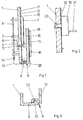
- FIG. 1 shows, from an instrument cluster, a base body 1 made of plastic, which has spacers 2 on its rear side, which keep a rigid printed circuit board 3 at a distance from the main body 1.
- a pointer drive 4 is attached, with an indicator shaft 5 penetrates an opening 6 of the base body 1.
- a pointer 7 is attached to this pointer shaft 5.
- the main body 1 has on its lower side a transverse to its main extension plane web 8, which is connected via a hinge 9 formed as a hinge with a support body 10.
- This support body 10 extends parallel to the base body 1 and covers a the pointer shaft 5 and the aperture 6 comprehensive range of the base body 1 from.
- a liquid crystal display 11 is arranged, the driver information z. B. a vehicle navigation system visualized.
- the pointer 7 of the instrument cluster according to the invention covers a first display area 15, while the liquid crystal display 11 forms a second display area 16.
- a flexible circuit board 12 which extends over the front of the base body 1 and the support body 10 and which has a defined angle bent connecting portion 13, which leads to the rigid circuit board 3 and with it by a z. B. temple soldering 14 is connected.
- Both the base body 1 and the support body 10 have a plurality of conical body, for example, 17, 18, which penetrate the flexible circuit board 12 and thereby fix them.
- dials not shown press the light boxes on the flexible circuit board 12 and so hold the flexible circuit board 12.
- the dials may be latched to the base body 1, for example, at the edge.
- FIG. 2 shows that pointer drives 19 can also be arranged on the flexible circuit board 12 with a pointer shaft 21, which penetrate the flexible printed circuit board 12 and the main body 1 with snap feet 20 and are latched on the rear side of the main body 1.
- these pointer drives 19 hold the flexible circuit board 12 on the base body 1.
- light boxes not shown, can be arranged and held on the base body 1 or the support body 10.
- dials not shown press the light boxes on the flexible circuit board 12 and so hold the flexible circuit board 12. The dials may be latched to the base body 1, for example, at the edge.
- the pointer drive 19 has resilient contacts on its underside, which rest resiliently on printed conductors of the flexible printed circuit board 12, so that a contact takes place without soldering.
- FIG. 3 shows a partial region of the web 8 and of the support body 10 connected thereto via the hinge 9. It can be seen that the support body 10 has a latching body 22 which, in the position of the support body 10 defined by the web 8, has a catch 23 of FIG Web 8 is snapped and thereby the support body 10 in the illustrated angular position in which it extends to the main body 1, fixed.
- Figure 4 illustrates how the flexible circuit board 12 by the z. B. iron soldering 14 is connected to the rigid circuit board 3. Furthermore, a horseshoe-shaped cut-out 24 is known, through which a central region 25 arises, which rests on the support body 10 shown in FIGS. 1 and 3. In contrast, edge regions 26, 27 and a region 28 surrounding the cutout 24 on the outside serve to rest on the base body 1.
- the flexible circuit board 12 can be optimally adapted by this design different angular orientations and different heights of the base body 1 and the support body 10. Also visible in the figure 4 openings 29, 30, through which the conical bodies 17, 18 shown in Figure 1 lead to fix the flexible circuit board 12. Through openings 31, 32, the locking feet 20 of the pointer drives 19 can be performed.
Landscapes
- Engineering & Computer Science (AREA)
- Chemical & Material Sciences (AREA)
- Combustion & Propulsion (AREA)
- Transportation (AREA)
- Mechanical Engineering (AREA)
- Instrument Panels (AREA)
- Mounting Of Printed Circuit Boards And The Like (AREA)
- Multi-Conductor Connections (AREA)
- Coupling Device And Connection With Printed Circuit (AREA)
- Combinations Of Printed Boards (AREA)
Claims (11)
- Instrument combiné ayant un corps de base (1) portant, sur Sa face arrière, une carte à circuits imprimés rigide (3) et comportant des zones d'affichage, où une carte à circuits imprimés souple (12) est disposée sur la face avant du corps de base (1) et a une zone de raccordement (13) placée sous un angle défini dans une direction différente à une zone de bordure de la carte à circuits imprimés rigide (3), caractérisé par le fait que les zones d'affichage s'étendent sous divers angles l'une par rapport à l'autre et parmi lesquelles au moins l'une est à un niveau de hauteur différent par rapport à une autre zone d'affichage, que le corps de base (1) a une barrette (8) perpendiculaire au plan principal du corps de base et à l'extrémité libre de laquelle est fixé, au moyen d'une charnière (9), un support (10) pour au moins une deuxième zone d'affichage (16), que la carte à circuits imprimés souple (12) s'étend sur la face avant du support (10).
- Instrument combiné selon la revendication 1, caractérisé par le fait que la zone de raccordement (13) est reliée à la carte à circuits imprimés rigide (3) par un brasage en étrier (14), un collage conducteur de l'électricité ou une fiche à force d'insertion nulle.
- Instrument combiné selon la revendication 1, caractérisé par le fait que la carte à circuits imprimés rigide (3) et la carte à circuits imprimés souple (12) sont fabriquées en une seule pièce en tant que carte à circuits imprimés rigide/souple.
- Instrument combiné selon la revendication 1, caractérisé par le fait que la charnière (9) du support (10) est une charnière à membrane.
- Instrument combiné selon au moins l'une des revendications précédentes, caractérisé par le fait que, sur la face arrière du support (10), est disposé au moins un corps d' arrêt (22) dirigé perpendiculairement à la direction principale du support et que la barrette (8) comporte au moins un crochet (23) destiné à s'encliqueter avec le corps d'arrêt (22) lorsque le support (10) se trouve dans une position définie par rapport au corps de base (1).
- Instrument combiné selon au moins l'une des revendications précédentes, caractérisé par le fait que la carte à circuits imprimés souple (12) a plusieurs ouvertures (29, 30) à travers chacune desquelles fait saillie un corps conique (17, 18) dépassant du corps de base (1) ou du support (10).
- Instrument combiné selon au moins l'une des revendications précédentes, caractérisé par le fait que, sur la carte à circuits imprimés souple (12), sont disposés des entraînements d'aiguille (19), des lampes et / ou d'autres composants, qui passent, par des pattes de fixation (20), à travers la carte à circuits imprimés souple (12) et s'encliquettent dans le corps de base (1) ou le support (10).
- Instrument combiné selon la revendication 7, caractérisé par le fait que les entraînements d'aiguille (19), et / ou les lampes et / ou les autres composants ont des contacts élastiques qui, dans l'état assemblé, s'appliquent en faisant ressort sur des pistes conductibles de la carte à circuits imprimés souple (12) et établissent le raccordement électrique.
- Instrument combiné selon au moins l'une des revendications précédentes, caractérisé par le fait que, sur la carte à circuits imprimés rigide (3), est disposé un entraînement d'aiguille (4) pour un tachymètre ou un autre affichage analogique et que le support (10) recouvre, dans l'état encliqueté, une zone comportant l'entraînement d'aiguille (4).
- Instrument combiné selon au moins l'une des revendications précédentes, caractérisé par le fait qu'un affichage à cristaux liquides (11) et/ou d'autres affichages sont installés sur le support (10).
- Instrument combiné selon au moins l'une des revendications précédentes, caractérisé par le fait que la connectique électronique est, dans l'espace, séparée des composants électroniques.
Applications Claiming Priority (2)
| Application Number | Priority Date | Filing Date | Title |
|---|---|---|---|
| DE19943571 | 1999-09-13 | ||
| DE19943571A DE19943571A1 (de) | 1999-09-13 | 1999-09-13 | Kombiinstrument |
Publications (3)
| Publication Number | Publication Date |
|---|---|
| EP1084893A2 EP1084893A2 (fr) | 2001-03-21 |
| EP1084893A3 EP1084893A3 (fr) | 2004-03-24 |
| EP1084893B1 true EP1084893B1 (fr) | 2006-10-11 |
Family
ID=7921675
Family Applications (1)
| Application Number | Title | Priority Date | Filing Date |
|---|---|---|---|
| EP00116854A Expired - Lifetime EP1084893B1 (fr) | 1999-09-13 | 2000-08-04 | Instrument combiné |
Country Status (3)
| Country | Link |
|---|---|
| US (1) | US6433701B1 (fr) |
| EP (1) | EP1084893B1 (fr) |
| DE (2) | DE19943571A1 (fr) |
Families Citing this family (7)
| Publication number | Priority date | Publication date | Assignee | Title |
|---|---|---|---|---|
| DE10214038C1 (de) * | 2002-03-27 | 2003-07-03 | Sai Automotive Sal Gmbh | Vorrichtung zum Halten eines Kombiinstruments und Instrumententafel |
| DE102004028481A1 (de) | 2004-06-11 | 2005-12-29 | Volkswagen Ag | Anzeigevorrichtung für ein Kraftfahrzeug |
| DE102005042695B4 (de) | 2004-12-30 | 2018-01-25 | Volkswagen Ag | Kraftfahrzeug mit einer Anzeigeanordnung |
| JP4762590B2 (ja) * | 2005-03-31 | 2011-08-31 | 日本精機株式会社 | 指示計器 |
| US7427143B1 (en) * | 2005-06-30 | 2008-09-23 | Yazaki North America, Inc. | Instrument cluster with three-dimensional display |
| DE102006032118B4 (de) | 2006-07-12 | 2022-03-03 | Volkswagen Ag | Kombiinstrument für ein Kraftfahrzeug und Kraftfahrzeug |
| CN111288364A (zh) * | 2018-12-07 | 2020-06-16 | 上海航空电器有限公司 | 一种告警信号灯盒导光板结构 |
Family Cites Families (17)
| Publication number | Priority date | Publication date | Assignee | Title |
|---|---|---|---|---|
| US4025896A (en) * | 1975-06-11 | 1977-05-24 | Amp Incorporated | Illuminated display system and method of wiring said system |
| US4304976A (en) * | 1978-03-16 | 1981-12-08 | Texas Instruments Incorporated | Capacitive touch switch panel |
| DE3800572A1 (de) * | 1987-10-30 | 1989-07-20 | Vdo Schindling | Kombinationsinstrument fuer kraftfahrzeuge |
| FR2626536B1 (fr) * | 1988-02-01 | 1990-07-13 | Sagem | Agencement de tableau de bord ou de partie de tableau de bord, notamment pour vehicules automobiles |
| DE476322T1 (de) * | 1990-09-10 | 1992-07-02 | Yokogawa Electric Corp., Musashino, Tokio/Tokyo | Gehaeusenanordnung fuer eine elektronische anlage. |
| US5255155A (en) * | 1990-09-19 | 1993-10-19 | Sumitomo Wiring Systems, Ltd. | Structure of electric circuit panel for instrument panel of automobile and method for forming the same |
| JPH04154436A (ja) * | 1990-10-17 | 1992-05-27 | Hitachi Ltd | 車載用液晶表示計器盤のシールド構造 |
| US5138528A (en) * | 1991-02-06 | 1992-08-11 | Amp Incorporated | Electrical packaging system and components therefor |
| DE4240456A1 (de) * | 1992-12-02 | 1994-07-28 | Vdo Schindling | Zifferblattanordnung für ein Kombinations-Instrument |
| DE4315027A1 (de) * | 1992-12-02 | 1994-06-09 | Vdo Schindling | Kombinations-Instrument |
| DE4332716A1 (de) * | 1993-09-25 | 1995-03-30 | Vdo Schindling | Kombinations-Instrument |
| JP3101993B2 (ja) * | 1994-10-31 | 2000-10-23 | 日本精機株式会社 | 液晶表示装置 |
| DE19632381A1 (de) * | 1996-08-10 | 1998-02-12 | Mannesmann Vdo Ag | Kombinationsinstrument |
| US5917149A (en) * | 1997-05-15 | 1999-06-29 | Daimlerchrysler Corporation | Flexible circuit board interconnect with strain relief |
| DE19737787B4 (de) * | 1997-08-29 | 2006-05-24 | Robert Bosch Gmbh | Anzeigeeinrichtung |
| DE19819393C2 (de) * | 1998-04-30 | 2001-10-18 | Bosch Gmbh Robert | Kombiinstrument und entpsrechendes Herstellungsverfahren |
| DE19819821C1 (de) * | 1998-05-04 | 1999-09-30 | Bosch Gmbh Robert | Kombiinstrument und entsprechendes Herstellungsverfahren |
-
1999
- 1999-09-13 DE DE19943571A patent/DE19943571A1/de not_active Withdrawn
-
2000
- 2000-08-04 DE DE50013598T patent/DE50013598D1/de not_active Expired - Lifetime
- 2000-08-04 EP EP00116854A patent/EP1084893B1/fr not_active Expired - Lifetime
- 2000-08-28 US US09/649,339 patent/US6433701B1/en not_active Expired - Fee Related
Also Published As
| Publication number | Publication date |
|---|---|
| DE19943571A1 (de) | 2001-03-15 |
| US6433701B1 (en) | 2002-08-13 |
| DE50013598D1 (de) | 2006-11-23 |
| EP1084893A3 (fr) | 2004-03-24 |
| EP1084893A2 (fr) | 2001-03-21 |
Similar Documents
| Publication | Publication Date | Title |
|---|---|---|
| EP2076413B1 (fr) | Systeme de raccordement comprenant un cablage externe sur des logements de moteurs d'essuie-glaces | |
| DE102004031707B4 (de) | Intelligenter Anschlusskasten für Kraftfahrzeuge | |
| DE102010023293B4 (de) | Kamera für ein Kraftfahrzeug | |
| DE3903229A1 (de) | Elektronischer schaltkreis | |
| DE20018538U1 (de) | Sensormodul | |
| DE3902956A1 (de) | Anordnung fuer eine instrumententafel oder einen instrumententafelteil, insbesondere fuer kraftfahrzeuge | |
| EP1080977B1 (fr) | Combiné indicateur | |
| EP1084893A2 (fr) | Instrument combiné | |
| WO2005094145A1 (fr) | Dispositif comprenant un moteur electrique et une carte de circuits imprimes principale et procede de montage | |
| DE102008040186B4 (de) | Trägerstruktur für ein Kombiinstrument, Kombiinstrument und Kraftfahrzeug | |
| DE19819393C2 (de) | Kombiinstrument und entpsrechendes Herstellungsverfahren | |
| DE102008035420A1 (de) | Modulare Schaltungsanordnung | |
| DE19819821C1 (de) | Kombiinstrument und entsprechendes Herstellungsverfahren | |
| EP2332396B1 (fr) | Boîtier pour un circuit électrique | |
| DE102008023714B4 (de) | Anordnung mit einem Hauptträger und einer Leiterplatte mit Bauelementen | |
| DE2805583A1 (de) | Anordnung fuer betaetigungselemente und zugeordnete funktionselemente | |
| DE4107620A1 (de) | Elektrisches geraet, insbesondere schalt- oder steuergeraet fuer kraftfahrzeuge | |
| EP1005693B1 (fr) | Transducteur ultrasonore comportant une platine montee dans le sens longitudinal dudit transducteur, pour un circuit electrique | |
| AT10686U1 (de) | Mobiles elektrisches gerät für fahrzeuge | |
| DE10337443A1 (de) | Schaltungsanordnung insbesondere für ein Kraftfahrzeug- Insassenschutzsystem | |
| DE102010047521A1 (de) | Anzeigevorrichtung für einen Kraftwagen | |
| DE102024133659A1 (de) | Fahrzeugsteuereinheit, Fahrzeug und Verfahren zur Montage einer Fahrzeugsteuereinheit | |
| DE4339314C2 (de) | Anzeigeeinheit, insbesondere Kombinationsinstrument | |
| DE19813044A1 (de) | Armaturentafel | |
| DE102024210210A1 (de) | Stanzbiegeteil für eine Knopfzellenbatteriehalterung, Knopfzellenbatteriehalterung und Vorrichtung |
Legal Events
| Date | Code | Title | Description |
|---|---|---|---|
| PUAI | Public reference made under article 153(3) epc to a published international application that has entered the european phase |
Free format text: ORIGINAL CODE: 0009012 |
|
| AK | Designated contracting states |
Kind code of ref document: A2 Designated state(s): AT BE CH CY DE DK ES FI FR GB GR IE IT LI LU MC NL PT SE |
|
| AX | Request for extension of the european patent |
Free format text: AL;LT;LV;MK;RO;SI |
|
| RAP1 | Party data changed (applicant data changed or rights of an application transferred) |
Owner name: SIEMENS AKTIENGESELLSCHAFT |
|
| PUAL | Search report despatched |
Free format text: ORIGINAL CODE: 0009013 |
|
| AK | Designated contracting states |
Kind code of ref document: A3 Designated state(s): AT BE CH CY DE DK ES FI FR GB GR IE IT LI LU MC NL PT SE |
|
| AX | Request for extension of the european patent |
Extension state: AL LT LV MK RO SI |
|
| 17P | Request for examination filed |
Effective date: 20040924 |
|
| AKX | Designation fees paid |
Designated state(s): DE FR GB |
|
| 17Q | First examination report despatched |
Effective date: 20050124 |
|
| GRAP | Despatch of communication of intention to grant a patent |
Free format text: ORIGINAL CODE: EPIDOSNIGR1 |
|
| GRAS | Grant fee paid |
Free format text: ORIGINAL CODE: EPIDOSNIGR3 |
|
| GRAA | (expected) grant |
Free format text: ORIGINAL CODE: 0009210 |
|
| AK | Designated contracting states |
Kind code of ref document: B1 Designated state(s): DE FR GB |
|
| REG | Reference to a national code |
Ref country code: GB Ref legal event code: FG4D Free format text: NOT ENGLISH |
|
| REF | Corresponds to: |
Ref document number: 50013598 Country of ref document: DE Date of ref document: 20061123 Kind code of ref document: P |
|
| ET | Fr: translation filed | ||
| GBV | Gb: ep patent (uk) treated as always having been void in accordance with gb section 77(7)/1977 [no translation filed] |
Effective date: 20061011 |
|
| PLBE | No opposition filed within time limit |
Free format text: ORIGINAL CODE: 0009261 |
|
| STAA | Information on the status of an ep patent application or granted ep patent |
Free format text: STATUS: NO OPPOSITION FILED WITHIN TIME LIMIT |
|
| 26N | No opposition filed |
Effective date: 20070712 |
|
| PG25 | Lapsed in a contracting state [announced via postgrant information from national office to epo] |
Ref country code: GB Free format text: LAPSE BECAUSE OF FAILURE TO SUBMIT A TRANSLATION OF THE DESCRIPTION OR TO PAY THE FEE WITHIN THE PRESCRIBED TIME-LIMIT Effective date: 20061011 |
|
| REG | Reference to a national code |
Ref country code: FR Ref legal event code: TP |
|
| PGFP | Annual fee paid to national office [announced via postgrant information from national office to epo] |
Ref country code: DE Payment date: 20130831 Year of fee payment: 14 |
|
| PGFP | Annual fee paid to national office [announced via postgrant information from national office to epo] |
Ref country code: FR Payment date: 20130823 Year of fee payment: 14 |
|
| REG | Reference to a national code |
Ref country code: DE Ref legal event code: R119 Ref document number: 50013598 Country of ref document: DE |
|
| REG | Reference to a national code |
Ref country code: DE Ref legal event code: R119 Ref document number: 50013598 Country of ref document: DE Effective date: 20150303 |
|
| REG | Reference to a national code |
Ref country code: FR Ref legal event code: ST Effective date: 20150430 |
|
| PG25 | Lapsed in a contracting state [announced via postgrant information from national office to epo] |
Ref country code: DE Free format text: LAPSE BECAUSE OF NON-PAYMENT OF DUE FEES Effective date: 20150303 |
|
| PG25 | Lapsed in a contracting state [announced via postgrant information from national office to epo] |
Ref country code: FR Free format text: LAPSE BECAUSE OF NON-PAYMENT OF DUE FEES Effective date: 20140901 |