EP1084951A2 - Ensemble nacelle pour turbo-moteur à combustion - Google Patents
Ensemble nacelle pour turbo-moteur à combustion Download PDFInfo
- Publication number
- EP1084951A2 EP1084951A2 EP00307682A EP00307682A EP1084951A2 EP 1084951 A2 EP1084951 A2 EP 1084951A2 EP 00307682 A EP00307682 A EP 00307682A EP 00307682 A EP00307682 A EP 00307682A EP 1084951 A2 EP1084951 A2 EP 1084951A2
- Authority
- EP
- European Patent Office
- Prior art keywords
- gas turbine
- engine
- assembly
- nacelle assembly
- mounting
- Prior art date
- Legal status (The legal status is an assumption and is not a legal conclusion. Google has not performed a legal analysis and makes no representation as to the accuracy of the status listed.)
- Granted
Links
Images


Classifications
-
- B—PERFORMING OPERATIONS; TRANSPORTING
- B64—AIRCRAFT; AVIATION; COSMONAUTICS
- B64D—EQUIPMENT FOR FITTING IN OR TO AIRCRAFT; FLIGHT SUITS; PARACHUTES; ARRANGEMENT OR MOUNTING OF POWER PLANTS OR PROPULSION TRANSMISSIONS IN AIRCRAFT
- B64D33/00—Arrangement in aircraft of power plant parts or auxiliaries not otherwise provided for
- B64D33/02—Arrangement in aircraft of power plant parts or auxiliaries not otherwise provided for of combustion air intakes
-
- B—PERFORMING OPERATIONS; TRANSPORTING
- B64—AIRCRAFT; AVIATION; COSMONAUTICS
- B64D—EQUIPMENT FOR FITTING IN OR TO AIRCRAFT; FLIGHT SUITS; PARACHUTES; ARRANGEMENT OR MOUNTING OF POWER PLANTS OR PROPULSION TRANSMISSIONS IN AIRCRAFT
- B64D33/00—Arrangement in aircraft of power plant parts or auxiliaries not otherwise provided for
- B64D33/02—Arrangement in aircraft of power plant parts or auxiliaries not otherwise provided for of combustion air intakes
- B64D2033/0206—Arrangement in aircraft of power plant parts or auxiliaries not otherwise provided for of combustion air intakes comprising noise reduction means, e.g. acoustic liners
-
- B—PERFORMING OPERATIONS; TRANSPORTING
- B64—AIRCRAFT; AVIATION; COSMONAUTICS
- B64D—EQUIPMENT FOR FITTING IN OR TO AIRCRAFT; FLIGHT SUITS; PARACHUTES; ARRANGEMENT OR MOUNTING OF POWER PLANTS OR PROPULSION TRANSMISSIONS IN AIRCRAFT
- B64D33/00—Arrangement in aircraft of power plant parts or auxiliaries not otherwise provided for
- B64D33/02—Arrangement in aircraft of power plant parts or auxiliaries not otherwise provided for of combustion air intakes
- B64D2033/0266—Arrangement in aircraft of power plant parts or auxiliaries not otherwise provided for of combustion air intakes specially adapted for particular type of power plants
- B64D2033/0286—Arrangement in aircraft of power plant parts or auxiliaries not otherwise provided for of combustion air intakes specially adapted for particular type of power plants for turbofan engines
Definitions
- the present invention relates to a ducted gas turbine engine and includes a nacelle assembly which is detachably connected to a ducted gas turbine engine.
- Ducted gas turbine engines usually comprise a core engine which drives a propulsive fan assembly.
- the fan assembly comprises a number of radially extending aerofoil blades mounted on a common hub and enclosed within a generally cylindrical casing assembly.
- the fan assembly and casing assembly are encircled by a generally annular nacelle assembly which forms the air intake of the engine and is aerodynamically shaped.
- the nacelle may extend both forward and rearward, relative to the direction of airflow, of the fan assembly.
- the occurrence of a part or all of one or more of the fan blades becoming detached from the fan assembly and impacting the casing assembly is hereinafter termed a FBO (fan blade off) event.
- the casing assembly surrounding the fan assembly is specifically designed to contain the detached blade or blade portion.
- the nacelle is not damaged during the FBO event as the casing assembly is subject to distortion. It is also important to remove the possibility of further damage to the nacelle, after the FBO event, resulting from vibrations during run down and subsequent windmilling due to the fan assembly being out of balance.
- Run down being hereinafter defined as the deceleration of axial rotational speed of the engine from the rotational speed at which a fan blade or part of a fan blade has been released and caused safety systems to shut down the engine.
- Windmilling being hereinafter defined as the axial rotation of the fan assembly arising from air ingressing the engine due to the forward speed of the aircraft after engine shut down.
- the nacelle assembly may be attached to a component of the engine and/or an engine support pylon assembly with the necessary access to the engine and engine core mounted accessories usually made by either opening fan cowl doors located in the body of the nacelle as described in WO93/02920 or by the nacelle assembly comprising two part-circular portions acting in a clam-shell like manner as described in US5205513.
- the nacelle assembly is commonly attached to the fan casing as described in US4044973, with such attachments being required to be particularly robust to maintain attachment after a FBO event.
- the nacelle designs, in particular the attachment means to the engine and/or pylon, of the prior art herein cited lend themselves to complex and heavy, thus expensive, assemblies.
- the nacelle assemblies also appear to be prone to damage during a FBO event and subsequent vibrational damage caused by windmilling of the out of balance fan assembly during fly home.
- a nacelle assembly adapted for mounting on a ducted fan gas turbine engine comprising a generally annular body having an air inlet and an air outlet, the generally annular body encircling a region of the engine when working in operative association with the engine and has a first attachment means to a rigid member and a second attachment means to a casing assembly on the engine wherein the second attachment means is frangible.
- the nacelle assembly is adapted for mounting on a gas turbine engine wherein the casing assembly comprises a containment casing and surrounds a fan assembly.
- the nacelle assembly is adapted for mounting on a gas turbine engine wherein the second attachment means provides support in the radial direction.
- the nacelle assembly is adapted for mounting on a gas turbine wherein the second attachment means detaches the nacelle assembly from the casing assembly during a FBO event.
- a nacelle assembly adapted for mounting on a gas turbine wherein the rigid member is a component of the engine.
- the nacelle assembly is adapted for mounting on a gas turbine engine wherein the rigid member is a component of a pylon structure or an aircraft structure.
- the nacelle assembly is adapted for mounting on a gas turbine engine wherein the first attachment means provides support for the nacelle in the radial, axial and circumferential directions.
- the nacelle assembly is adapted for mounting on a gas turbine engine wherein the first attachment means is a releasable attachment.
- the nacelle assembly is adapted for mounting on a gas turbine engine wherein the annular body comprises a radially outer facing and a radially inner facing defining a space therebetween.
- the nacelle assembly is adapted for mounting on a gas turbine engine wherein the annular body comprises the outer facing and inner facing joining and extending rearward of the space to form a single skin.
- the nacelle assembly is adapted for mounting on a gas turbine engine wherein the outer facing and inner facing are constructed from sandwich constructions.
- the nacelle assembly is adapted for mounting on a gas turbine engine wherein the space contains a lightweight core, the lightweight core attached to both the outer facing and the inner facing.
- the nacelle assembly is adapted for mounting on a gas turbine engine wherein the space contains a connector, the connector attached to both the outer facing and the inner facing.
- the nacelle assembly is adapted for mounting on a gas turbine engine wherein the connector extends substantially in the axial direction.
- the nacelle assembly is adapted for mounting on a gas turbine engine wherein the connector extends substantially in the circumferential direction.
- the nacelle assembly is adapted for mounting on a gas turbine wherein the annular body includes an access panel.
- the nacelle assembly is adapted for mounting on a gas turbine engine wherein an engine accessory is operationally located within the space in the annular body.
- a method for assembling a nacelle assembly with an engine comprises the steps aligning the nacelle assembly and the engine substantially parallel to the engine rotation axis, translating the nacelle assembly along the axis to engage the first and second attachments, and securing the first attachment.
- a method for removing a nacelle assembly from an engine comprises the steps releasing the first attachment, translating the nacelle assembly substantially parallel to the axis of the engine.
- a ducted gas turbine engine 20 of known general configuration and method of operation, comprises a rotational axis 21 of the engine 20, an engine core 22 surrounded by a core casing 24 and which drives a propulsive fan assembly 26.
- the fan assembly 26 comprises a retention disc 28 with an array of radially extending aerofoil blades 30.
- the engine 20 is secured to an aircraft wing (not shown) from the engine core casing 24 by an engine support pylon assembly 32 in known manner.
- the engine 20 may be mounted to the aircraft structure (not shown)
- a nacelle assembly 40 encircles a region of the engine 20.
- a casing assembly 34 surrounding the fan assembly 26 and secured to an annular array of radially extending vanes 36 comprises a containment casing 38 for retention of a blade 30 or a portion of a blade 30 during a FBO event.
- the nacelle assembly 40 comprises an air inlet 42 and an air outlet 44 and a generally annular body 46 which encircles a region of the engine 20.
- the nacelle 40 encircles a region of both the casing assembly 34 and the fan assembly 26 and is extended rearwards for attachment by a first attachment means 48 to a strengthening ring 50.
- the first attachment 48 means is made by conventional means as known in the art so as to provide axial, radial and circumferential support to the nacelle assembly 40.
- the nacelle assembly 40 is also attached at the front of the casing assembly 34 by a second attachment means 52, the second attachment means 52 is a frangible attachment 52 of construction as known in the art.
- the second attachment means 52 located upstream of the first attachment means 48, provides support in the radial direction assisting alignment of a gas washed inner nacelle surface 54 and a casing assembly inner surface 56.
- the frangible attachment 52 is designed to detach the nacelle 40 and the engine casing assembly 34 during a FBO event.
- a blade 30 or blade portion 30 is released from the fan assembly 26 and strikes the containment casing 38, part of the casing assembly 34, causing the containment casing 38 and the casing assembly 34 to distort form their original shape.
- the nacelle 40 detaches from the engine casing assembly 34 during the FBO event so that the nacelle assembly 40 is not damaged.
- the nacelle assembly 40 is no longer attached to the casing assembly 34 after the FBO event as it is not subject to the consequential vibrations arising from the out of balance of the fan assembly during run down and windmilling.
- the strengthening ring 50 is attached to the engine core casing 24 by a rigid member 58 as known in the art.
- the nacelle assembly 40 also comprises an acoustic lining 60 configured and implemented as known in the art.
- the nacelle assembly 40 also comprises an anti-icing means 62 as known in the art.
- the nacelle assembly 40 is configured to form an annular space 64 radially outward of the casing assembly 34 to accommodate an engine accessory 66.
- the annular space 64 also provides a space for the casing assembly 34 to deflect without contacting the nacelle assembly 40 during a FBO event.
- the nacelle assembly 40 provides an aerodynamic external profile for the engine 20 and an aerodynamic air inlet 42 and air outlet 44 for the propulsive fan assembly 26.
- the construction of the nacelle assembly 40 and in particular the annular body 46 is intrinsic to the implementation of the invention. It is intended that the nacelle body 46 is both lightweight and strong.
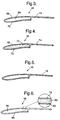
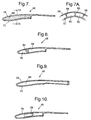
- the following descriptions with reference to figures 3 to 10 give details of further embodiments of the annular body 46 in accordance with the present invention.
- the nacelle assembly 40 carries aerodynamic loads and loads generated from flexural displacements of the engine 20 and/or the pylon assembly 32.
- the method for removal of the nacelle assembly 40, particularly for access to the engine 20, is by way of releasing the first attachment means 48 and translating the nacelle assembly 40 in a generally forward axial direction relative to the engine 20.
- the second attachment means 52 being so arranged as to disengage the nacelle assembly from the casing assembly 34 when the nacelle assembly 40 is translated forward with respect to the engine 20.
- the method for attachment of the nacelle assembly 40 to the engine 20 is by way of translating the nacelle assembly 40 in a generally rearward axial direction relative to the engine 20 thereby engaging the second attachment means 52 and first attachment means 48.
- the first attachment means 48 may be conventional clamps, "V"-blades or latches.
- annular body 46 which performs the aforementioned load carrying. It is important for the annular body 46 to be lightweight and relatively strong particularly after a FBO event. The annular body 46 is required to remain intact and operational throughout the remainder of the flight of the aircraft (not shown) . After a FBO event the annular body 46 is attached only by the first attachment means 48 and is subject to aerodynamic loads and loads generated from flexural displacements of the engine 20 and/or the pylon assembly 32. The construction of the annular body 46 is therefore required to be lightweight and strong and the following embodiments hereafter of the present invention describe such constructions.
- the construction of the nacelle body 46 is generally annular with respect to the rotational axis 21 of the engine 20 and comprises a radially outer facing 68 and radially inner facing 70. Both the outer facing 68 and the inner facing 70 are relatively thin, strong and stiff and define an internal space 86 therebetween.
- the configuration of the nacelle assembly 46 is designed to form a annular space 64 (figure 2) radially outward of the casing assembly 34 to accommodate engine accessories 66. This is achieved by discontinuing the internal space 86 in the region of the second attachment means 52 and joining the outer facing 68 with the inner facing 70 to form a single skin 74.
- the single skin 74 extends rearward to the first attachment means 48 at the strengthening ring 50.
- the construction of the nacelle body 46 comprises a relatively thin, strong and stiff radially outer facing 68 and radially inner facing 70 generally surrounding a lightweight main core 72 as known in the art as a sandwich construction.
- the purpose of the main core 66 being to transfer bending shear, torque, compressive and tensile stresses and loads between the outer facing 68 and the inner facing 70.
- annular body 46 as described with reference to the embodiment shown in figure 3 having an access panel 76 located in the single skin 74.
- the access panel 76 allowing access to the engine accessory 66 without removal of the nacelle assembly 40.
- annular body 46 as described with reference to the embodiment shown in figures 3, 4 and 5 comprising items that are common to both, the outer facing 68 and the inner facing 70 are formed from sandwich constructions themselves with an outer sub-facing 78 and an inner sub-facing 80 generally surrounding a sub-core 82.
- the outer sub-facing 78 relating to an exterior surface 84 of the annular body 46.
- the embodiment described with reference to figure 5 may also comprise an internal space 86 rather than a main core 72.
- the embodiment described with reference to figure 5 may also comprise an access panel 76 as described with reference to figure 5.
- annular body 46 as described with reference to the embodiments shown in figures 3, 5, 6, 6A comprising an annular array of webs 88 connecting the outer facing 68 and the inner facing 70.
- Each web 88 extends axially to thereby define an array of voids 90 (figure 7A).
- the webs 88 may extend for the entire axial distance of the void 90 (figure 7A) or may extend for a portion of the axial distance of the void 90, so that the voids 90 are interconnected with each other.
- annular body 46 as described with reference to the embodiments shown in figures 3, 5, 6, 6A comprising a substantially annular connector 92 connecting the outer facing 68 and the inner facing 70.
- the connector 92 extends substantially radially between the outer facing 68 and the inner facing 70.
- annular body 46 as described with reference to the embodiments shown in figures 3, 4, 5, 6, 6A, 7, 7A, 8 comprising extending the internal space 86 rearward in the annular body 46.
- the internal space 86 may also comprise a main core 72 or any of the features such as the web 90 or the connector 92.
- an annular body 46 as described with reference to the embodiments shown in figures 3, 4, 5, 6, 6A, 7, 7A, 8, 9 comprising arranging the engine accessory 66 between the outer facing 68 and inner facing 70 of the annular body 46.
- the engine accessory 66 may be positioned substantially within the internal space 86, the void 92 or the annular void 94.
- first attachment means 48 may also be attached in a similar manner to any relatively rigid engine 20 component, such as the casing assembly 34, the annular array of vanes 36 or the rigid member 58.
- Suitable materials for the facing 68, 70, 78, 80 and single skin 74, access panel 76 and the web 88 and the connector 92 include thermoplastics and thermosets (eg. polythene, polycarbonate, polyethersulphone, polyetheretherketone (PEEK), polyvinylchloride (PVC), epoxy resin cured by amines, nylon, polytetraflouroethelene (PTFE)), resins (e.g. Epoxy, polyamides, phenolic, silicone, cyanoacrylates, anaerobics and acrylics), ceramics (e.g. silicon nitride, silicon carbide, glass-ceramics), aluminium alloys (e.g.
- thermoplastics and thermosets eg. polythene, polycarbonate, polyethersulphone, polyetheretherketone (PEEK), polyvinylchloride (PVC), epoxy resin cured by amines, nylon, polytetraflouroethelene (PTFE)),
- Suitable materials for the main core 72 and the sub-core 82 include expanded plastics (e.g. polyurethane), low density woods, honeycomb structures (e.g. aluminium, paper).
Landscapes
- Engineering & Computer Science (AREA)
- Chemical & Material Sciences (AREA)
- Combustion & Propulsion (AREA)
- Aviation & Aerospace Engineering (AREA)
- Structures Of Non-Positive Displacement Pumps (AREA)
- Wind Motors (AREA)
Applications Claiming Priority (2)
| Application Number | Priority Date | Filing Date | Title |
|---|---|---|---|
| GB9921935 | 1999-09-17 | ||
| GBGB9921935.4A GB9921935D0 (en) | 1999-09-17 | 1999-09-17 | A nacelle assembly for a gas turbine engine |
Publications (3)
| Publication Number | Publication Date |
|---|---|
| EP1084951A2 true EP1084951A2 (fr) | 2001-03-21 |
| EP1084951A3 EP1084951A3 (fr) | 2001-10-10 |
| EP1084951B1 EP1084951B1 (fr) | 2002-11-20 |
Family
ID=10861051
Family Applications (1)
| Application Number | Title | Priority Date | Filing Date |
|---|---|---|---|
| EP00307682A Expired - Lifetime EP1084951B1 (fr) | 1999-09-17 | 2000-09-06 | Ensemble nacelle pour turbo-moteur à combustion |
Country Status (4)
| Country | Link |
|---|---|
| US (1) | US6360989B1 (fr) |
| EP (1) | EP1084951B1 (fr) |
| DE (1) | DE60000813T2 (fr) |
| GB (1) | GB9921935D0 (fr) |
Cited By (10)
| Publication number | Priority date | Publication date | Assignee | Title |
|---|---|---|---|---|
| FR2855497A1 (fr) * | 2003-06-02 | 2004-12-03 | Rolls Royce Plc | Nacelle pour moteur a turbine a gaz |
| FR2898870A1 (fr) * | 2006-03-24 | 2007-09-28 | Aircelle Sa | Structure de virole d'entree d'air |
| FR2934247A1 (fr) * | 2008-07-25 | 2010-01-29 | Snecma | Nacelle de turboreacteur. |
| WO2010059301A3 (fr) * | 2008-11-19 | 2010-07-22 | General Electric Company | Conception d'entrée intégrée |
| US8186934B2 (en) | 2007-03-14 | 2012-05-29 | Rolls-Royce Plc | Casing assembly |
| EP2431578A3 (fr) * | 2010-09-16 | 2013-03-13 | Rolls-Royce plc | Agencement de palier de moteur à turbine à gaz |
| EP2148064A3 (fr) * | 2008-07-24 | 2013-10-23 | Rolls-Royce plc | Nacelle de turboréacteur |
| US8591172B2 (en) | 2009-09-25 | 2013-11-26 | Rolls-Royce Plc | Containment casing for an aero engine |
| FR2990928A1 (fr) * | 2012-05-24 | 2013-11-29 | Snecma | Nacelle de moteur a turbine a gaz |
| CN108327915A (zh) * | 2017-01-20 | 2018-07-27 | 通用电气公司 | 用于飞行器后风扇的机舱 |
Families Citing this family (28)
| Publication number | Priority date | Publication date | Assignee | Title |
|---|---|---|---|---|
| GB2385382B (en) * | 2002-02-13 | 2006-02-15 | Rolls Royce Plc | A cowl structure for a gas turbine engine |
| US20040244357A1 (en) * | 2003-06-05 | 2004-12-09 | Sloan Mark L. | Divergent chevron nozzle and method |
| US6920958B2 (en) * | 2003-10-17 | 2005-07-26 | The Boeing Company | Annular acoustic panel |
| US7866440B2 (en) * | 2006-07-21 | 2011-01-11 | Rohr, Inc. | System for joining acoustic cellular panel sections in edge-to-edge relation |
| US7797944B2 (en) | 2006-10-20 | 2010-09-21 | United Technologies Corporation | Gas turbine engine having slim-line nacelle |
| US7870721B2 (en) * | 2006-11-10 | 2011-01-18 | United Technologies Corporation | Gas turbine engine providing simulated boundary layer thickness increase |
| US8408491B2 (en) | 2007-04-24 | 2013-04-02 | United Technologies Corporation | Nacelle assembly having inlet airfoil for a gas turbine engine |
| US8205430B2 (en) * | 2007-05-16 | 2012-06-26 | United Technologies Corporation | Variable geometry nacelle assembly for a gas turbine engine |
| US8727267B2 (en) * | 2007-05-18 | 2014-05-20 | United Technologies Corporation | Variable contraction ratio nacelle assembly for a gas turbine engine |
| US8082726B2 (en) * | 2007-06-26 | 2011-12-27 | United Technologies Corporation | Tangential anti-swirl air supply |
| US8402739B2 (en) * | 2007-06-28 | 2013-03-26 | United Technologies Corporation | Variable shape inlet section for a nacelle assembly of a gas turbine engine |
| US9091214B2 (en) * | 2007-06-28 | 2015-07-28 | United Technologies Corporation | Reduced gearbox size by separate electrically powered engine oil system |
| US9228534B2 (en) * | 2007-07-02 | 2016-01-05 | United Technologies Corporation | Variable contour nacelle assembly for a gas turbine engine |
| US9004399B2 (en) * | 2007-11-13 | 2015-04-14 | United Technologies Corporation | Nacelle flow assembly |
| US9719428B2 (en) * | 2007-11-30 | 2017-08-01 | United Technologies Corporation | Gas turbine engine with pylon mounted accessory drive |
| US8186942B2 (en) * | 2007-12-14 | 2012-05-29 | United Technologies Corporation | Nacelle assembly with turbulators |
| US8192147B2 (en) * | 2007-12-14 | 2012-06-05 | United Technologies Corporation | Nacelle assembly having inlet bleed |
| US8769924B2 (en) * | 2008-05-30 | 2014-07-08 | United Technologies Corporation | Gas turbine engine assembly including accessory components within the nacelle |
| FR2932160B1 (fr) * | 2008-06-06 | 2010-11-26 | Airbus France | Support d'appareils de mesure intercale entre une motorisation et une entree d'air d'une nacelle d'aeronef |
| FR2938236B1 (fr) * | 2008-11-13 | 2011-04-15 | Aircelle Sa | Nacelle pour turboreacteur |
| US8469309B2 (en) * | 2008-12-24 | 2013-06-25 | General Electric Company | Monolithic structure for mounting aircraft engine |
| US8262050B2 (en) * | 2008-12-24 | 2012-09-11 | General Electric Company | Method and apparatus for mounting and dismounting an aircraft engine |
| US20140352797A1 (en) * | 2013-06-04 | 2014-12-04 | Rohr, Inc. | Aircraft jet engine |
| US9664113B2 (en) * | 2014-03-15 | 2017-05-30 | The Boeing Company | One piece inlet lip skin design |
| US10589869B2 (en) | 2018-07-25 | 2020-03-17 | General Electric Company | Nacelle inlet lip fuse structure |
| CN110805496B (zh) * | 2018-08-06 | 2020-09-08 | 中国航发商用航空发动机有限责任公司 | 航空发动机风扇叶片脱落事件降载装置 |
| US11085373B2 (en) | 2019-01-31 | 2021-08-10 | Rolls-Royce North American Technologies Inc. | Gas turbine engine with mount for interchangeable inlets |
| FR3097260B1 (fr) * | 2019-06-12 | 2021-06-11 | Safran Aircraft Engines | Carter de soufflante de turboréacteur |
Family Cites Families (12)
| Publication number | Priority date | Publication date | Assignee | Title |
|---|---|---|---|---|
| US4044973A (en) | 1975-12-29 | 1977-08-30 | The Boeing Company | Nacelle assembly and mounting structures for a turbofan jet propulsion engine |
| US4500252A (en) * | 1981-12-21 | 1985-02-19 | United Technologies Corporation | Beam for a containment structure |
| EP0104174B1 (fr) * | 1982-03-26 | 1987-12-16 | The Boeing Company | Structure de capot deformable pour entretoise de turbine a gaz |
| GB2228639B (en) | 1989-02-17 | 1992-07-15 | Motorola Semiconducteurs | Protected darlington transistor arrangement |
| GB9116986D0 (en) | 1991-08-07 | 1991-10-09 | Rolls Royce Plc | Gas turbine engine nacelle assembly |
| US5205513A (en) * | 1991-09-26 | 1993-04-27 | General Electric Company | Method and system for the removal of large turbine engines |
| GB2265418B (en) * | 1992-03-26 | 1995-03-08 | Rolls Royce Plc | Gas turbine engine casing |
| US5259724A (en) * | 1992-05-01 | 1993-11-09 | General Electric Company | Inlet fan blade fragment containment shield |
| GB9301457D0 (en) * | 1993-01-26 | 1993-03-17 | Short Brothers Plc | An aircraft propulsuve power unit |
| US5447411A (en) * | 1993-06-10 | 1995-09-05 | Martin Marietta Corporation | Light weight fan blade containment system |
| US5524847A (en) | 1993-09-07 | 1996-06-11 | United Technologies Corporation | Nacelle and mounting arrangement for an aircraft engine |
| FR2757823B1 (fr) * | 1996-12-26 | 1999-03-12 | Aerospatiale | Nacelle de turboreacteur a ecoulement laminaire |
-
1999
- 1999-09-17 GB GBGB9921935.4A patent/GB9921935D0/en not_active Ceased
-
2000
- 2000-09-06 EP EP00307682A patent/EP1084951B1/fr not_active Expired - Lifetime
- 2000-09-06 DE DE60000813T patent/DE60000813T2/de not_active Expired - Lifetime
- 2000-09-07 US US09/657,266 patent/US6360989B1/en not_active Expired - Lifetime
Cited By (15)
| Publication number | Priority date | Publication date | Assignee | Title |
|---|---|---|---|---|
| FR2855497A1 (fr) * | 2003-06-02 | 2004-12-03 | Rolls Royce Plc | Nacelle pour moteur a turbine a gaz |
| FR2898870A1 (fr) * | 2006-03-24 | 2007-09-28 | Aircelle Sa | Structure de virole d'entree d'air |
| WO2007110491A1 (fr) * | 2006-03-24 | 2007-10-04 | Aircelle | Structure de virole d'entree d'air |
| US8231332B2 (en) | 2006-03-24 | 2012-07-31 | Aircelle | Air inlet shroud structure |
| US8186934B2 (en) | 2007-03-14 | 2012-05-29 | Rolls-Royce Plc | Casing assembly |
| EP2148064A3 (fr) * | 2008-07-24 | 2013-10-23 | Rolls-Royce plc | Nacelle de turboréacteur |
| FR2934247A1 (fr) * | 2008-07-25 | 2010-01-29 | Snecma | Nacelle de turboreacteur. |
| JP2012509440A (ja) * | 2008-11-19 | 2012-04-19 | ゼネラル・エレクトリック・カンパニイ | 一体型吸気口設計 |
| US8152461B2 (en) | 2008-11-19 | 2012-04-10 | Mra Systems, Inc. | Integrated inlet design |
| WO2010059301A3 (fr) * | 2008-11-19 | 2010-07-22 | General Electric Company | Conception d'entrée intégrée |
| US8591172B2 (en) | 2009-09-25 | 2013-11-26 | Rolls-Royce Plc | Containment casing for an aero engine |
| EP2305985A3 (fr) * | 2009-09-25 | 2014-03-12 | Rolls-Royce plc | Boîtier de confinement pour moteur d'avion |
| EP2431578A3 (fr) * | 2010-09-16 | 2013-03-13 | Rolls-Royce plc | Agencement de palier de moteur à turbine à gaz |
| FR2990928A1 (fr) * | 2012-05-24 | 2013-11-29 | Snecma | Nacelle de moteur a turbine a gaz |
| CN108327915A (zh) * | 2017-01-20 | 2018-07-27 | 通用电气公司 | 用于飞行器后风扇的机舱 |
Also Published As
| Publication number | Publication date |
|---|---|
| EP1084951B1 (fr) | 2002-11-20 |
| DE60000813T2 (de) | 2003-03-27 |
| EP1084951A3 (fr) | 2001-10-10 |
| US6360989B1 (en) | 2002-03-26 |
| GB9921935D0 (en) | 1999-11-17 |
| DE60000813D1 (de) | 2003-01-02 |
Similar Documents
| Publication | Publication Date | Title |
|---|---|---|
| EP1084951B1 (fr) | Ensemble nacelle pour turbo-moteur à combustion | |
| US7434303B2 (en) | Nacelle assembly for a gas turbine engine | |
| US8267642B2 (en) | Inlet section of an aircraft engine nacelle | |
| EP2202153B1 (fr) | Structure monolithique pour l'assemblage de moteur d'avion | |
| EP2336500B1 (fr) | Méthode pour fabriquer un dispositif d'admission d'un moteur-fusée | |
| US5725354A (en) | Forward swept fan blade | |
| US4055041A (en) | Integrated gas turbine engine-nacelle | |
| US7866939B2 (en) | Liner for a gas turbine engine casing | |
| EP2346736B1 (fr) | Conception d'entrée intégrée | |
| EP3623295B1 (fr) | Entrée de nacelle, nacelle de moteur à turbine à gaz comportant une telle entrée et procédé de fabrication d'une telle entrée | |
| EP2333251A2 (fr) | Anneau de rétention de soufflante | |
| EP3009649B1 (fr) | Conduite d'écoulement externe intégrée et système de cadre avant destiné à être utilisé dans un moteur à turboréacteur et son procédé de fabrication | |
| US7850116B2 (en) | Ducted open rotor apparatus and method | |
| CN101210577A (zh) | 导叶和制造导叶的方法 | |
| US11725524B2 (en) | Engine airfoil metal edge | |
| JP2001041002A (ja) | 複合材翼 | |
| US20260071550A1 (en) | Variable pitch airfoil | |
| Blackhurst | Reinforced Plastics Design Rolls-Royce RB. 162 Lift Engine |
Legal Events
| Date | Code | Title | Description |
|---|---|---|---|
| PUAI | Public reference made under article 153(3) epc to a published international application that has entered the european phase |
Free format text: ORIGINAL CODE: 0009012 |
|
| AK | Designated contracting states |
Kind code of ref document: A2 Designated state(s): AT BE CH CY DE DK ES FI FR GB GR IE IT LI LU MC NL PT SE Kind code of ref document: A2 Designated state(s): DE FR GB |
|
| AX | Request for extension of the european patent |
Free format text: AL;LT;LV;MK;RO;SI |
|
| PUAL | Search report despatched |
Free format text: ORIGINAL CODE: 0009013 |
|
| AK | Designated contracting states |
Kind code of ref document: A3 Designated state(s): AT BE CH CY DE DK ES FI FR GB GR IE IT LI LU MC NL PT SE |
|
| AX | Request for extension of the european patent |
Free format text: AL;LT;LV;MK;RO;SI |
|
| 17P | Request for examination filed |
Effective date: 20010907 |
|
| GRAG | Despatch of communication of intention to grant |
Free format text: ORIGINAL CODE: EPIDOS AGRA |
|
| 17Q | First examination report despatched |
Effective date: 20011218 |
|
| GRAG | Despatch of communication of intention to grant |
Free format text: ORIGINAL CODE: EPIDOS AGRA |
|
| GRAH | Despatch of communication of intention to grant a patent |
Free format text: ORIGINAL CODE: EPIDOS IGRA |
|
| GRAH | Despatch of communication of intention to grant a patent |
Free format text: ORIGINAL CODE: EPIDOS IGRA |
|
| AKX | Designation fees paid |
Free format text: DE FR GB |
|
| GRAA | (expected) grant |
Free format text: ORIGINAL CODE: 0009210 |
|
| AK | Designated contracting states |
Kind code of ref document: B1 Designated state(s): DE FR GB |
|
| REG | Reference to a national code |
Ref country code: GB Ref legal event code: FG4D |
|
| REF | Corresponds to: |
Ref document number: 60000813 Country of ref document: DE Date of ref document: 20030102 |
|
| ET | Fr: translation filed | ||
| PLBE | No opposition filed within time limit |
Free format text: ORIGINAL CODE: 0009261 |
|
| STAA | Information on the status of an ep patent application or granted ep patent |
Free format text: STATUS: NO OPPOSITION FILED WITHIN TIME LIMIT |
|
| 26N | No opposition filed |
Effective date: 20030821 |
|
| REG | Reference to a national code |
Ref country code: FR Ref legal event code: PLFP Year of fee payment: 16 |
|
| REG | Reference to a national code |
Ref country code: FR Ref legal event code: PLFP Year of fee payment: 17 |
|
| REG | Reference to a national code |
Ref country code: FR Ref legal event code: PLFP Year of fee payment: 18 |
|
| PGFP | Annual fee paid to national office [announced via postgrant information from national office to epo] |
Ref country code: GB Payment date: 20170927 Year of fee payment: 18 Ref country code: FR Payment date: 20170925 Year of fee payment: 18 |
|
| PGFP | Annual fee paid to national office [announced via postgrant information from national office to epo] |
Ref country code: DE Payment date: 20170927 Year of fee payment: 18 |
|
| REG | Reference to a national code |
Ref country code: DE Ref legal event code: R119 Ref document number: 60000813 Country of ref document: DE |
|
| GBPC | Gb: european patent ceased through non-payment of renewal fee |
Effective date: 20180906 |
|
| PG25 | Lapsed in a contracting state [announced via postgrant information from national office to epo] |
Ref country code: DE Free format text: LAPSE BECAUSE OF NON-PAYMENT OF DUE FEES Effective date: 20190402 |
|
| PG25 | Lapsed in a contracting state [announced via postgrant information from national office to epo] |
Ref country code: FR Free format text: LAPSE BECAUSE OF NON-PAYMENT OF DUE FEES Effective date: 20180930 |
|
| PG25 | Lapsed in a contracting state [announced via postgrant information from national office to epo] |
Ref country code: GB Free format text: LAPSE BECAUSE OF NON-PAYMENT OF DUE FEES Effective date: 20180906 |