EP1084979A1 - Greifer einer heb- und senkbaren Aufnahmevorrichtung für von oben zu greifende Behälter - Google Patents
Greifer einer heb- und senkbaren Aufnahmevorrichtung für von oben zu greifende Behälter Download PDFInfo
- Publication number
- EP1084979A1 EP1084979A1 EP00250288A EP00250288A EP1084979A1 EP 1084979 A1 EP1084979 A1 EP 1084979A1 EP 00250288 A EP00250288 A EP 00250288A EP 00250288 A EP00250288 A EP 00250288A EP 1084979 A1 EP1084979 A1 EP 1084979A1
- Authority
- EP
- European Patent Office
- Prior art keywords
- cross member
- gripping
- elements
- gripper according
- hook
- Prior art date
- Legal status (The legal status is an assumption and is not a legal conclusion. Google has not performed a legal analysis and makes no representation as to the accuracy of the status listed.)
- Granted
Links
- 238000003780 insertion Methods 0.000 claims description 4
- 230000037431 insertion Effects 0.000 claims description 4
- 238000003698 laser cutting Methods 0.000 claims description 4
- 238000000034 method Methods 0.000 claims description 4
- 239000002184 metal Substances 0.000 abstract 1
- 238000010276 construction Methods 0.000 description 3
- 238000004519 manufacturing process Methods 0.000 description 3
- 230000035515 penetration Effects 0.000 description 2
- 241000196324 Embryophyta Species 0.000 description 1
- 240000006829 Ficus sundaica Species 0.000 description 1
- 239000000853 adhesive Substances 0.000 description 1
- 230000001070 adhesive effect Effects 0.000 description 1
- 238000005452 bending Methods 0.000 description 1
- 239000000969 carrier Substances 0.000 description 1
- 238000005520 cutting process Methods 0.000 description 1
- 238000006073 displacement reaction Methods 0.000 description 1
- 230000000284 resting effect Effects 0.000 description 1
Images



Classifications
-
- B—PERFORMING OPERATIONS; TRANSPORTING
- B66—HOISTING; LIFTING; HAULING
- B66C—CRANES; LOAD-ENGAGING ELEMENTS OR DEVICES FOR CRANES, CAPSTANS, WINCHES, OR TACKLES
- B66C1/00—Load-engaging elements or devices attached to lifting or lowering gear of cranes or adapted for connection therewith for transmitting lifting forces to articles or groups of articles
- B66C1/10—Load-engaging elements or devices attached to lifting or lowering gear of cranes or adapted for connection therewith for transmitting lifting forces to articles or groups of articles by mechanical means
- B66C1/62—Load-engaging elements or devices attached to lifting or lowering gear of cranes or adapted for connection therewith for transmitting lifting forces to articles or groups of articles by mechanical means comprising article-engaging members of a shape complementary to that of the articles to be handled
- B66C1/66—Load-engaging elements or devices attached to lifting or lowering gear of cranes or adapted for connection therewith for transmitting lifting forces to articles or groups of articles by mechanical means comprising article-engaging members of a shape complementary to that of the articles to be handled for engaging holes, recesses, or abutments on articles specially provided for facilitating handling thereof
Definitions
- the invention relates to a gripper of a lifting and lowering receiving device for containers to be gripped from above according to the preamble of claim 1.
- a generic gripper for from above loads to be gripped is provided.
- the gripper consists of a frame that is made of Cross and side members is formed, and is attached to an eyelet with a hoist connected.
- a pair of gripping elements are arranged on the cross beams, whose distance corresponds approximately to the length of the cross member. So that's the distance large compared to the gripping element dimensions (width, length, thickness).
- Each Gripping element consists of two hook elements in a common vertical Lay level and the hook tips are facing away from each other. The the Hook tips opposite surfaces of the two hook elements are each other facing and lie against each other in the ready position of the gripping element.
- the gripping elements extend vertically downwards and dive when they are put on of the frame onto the container in each case in a container opening, the Container openings in the container side wall are slit-shaped.
- the gripper is specially designed for standard containers which are open at the top and which are located in the vertical Side walls in the upper edge area extending into the side wall Have container openings.
- the hook elements are each Gripping elements in a gripping position can be swung apart (spreadable) where they are under grab the edge of the slit-shaped opening.
- the document DE 42 29 346 describes a vertical gripper for system containers in which a pair of gripping elements is assigned to each of two cross members. The gripping elements can be moved transversely to the stroke direction.
- the object of the invention is to provide a structurally simple gripper that consists of a few inexpensive to produce individual parts.
- each cross member has at least a pair of gripping elements and that the gripping elements of each pair are linearly displaceable in opposite directions along the cross member.
- the gripping elements for example, each fastened to a supporting element, are moved into the gripping position in that the supporting elements are each linearly displaced until the gripping elements engage under the corresponding adhesive elements on the container.
- the gripping elements of each pair are moved until they come to rest on the edges of the container opening.
- each cross member is made of two longitudinally displaceable Formed cross member plates and a gripping element of the pair is arranged on each cross member plate, so that the gripping elements of each pair are mutually displaceable along the cross member.
- the safety of gripping can be increased in that each gripping element of the Pair of two hook elements is formed, the one hook element on the one and the other hook element is arranged on the other cross member plate.
- each gripping element is expediently each other turned away, so that this the container opening on opposite side edges reach under.
- the trouble-free moving of the gripping elements from the pushed apart in the overlapping position is ensured by the fact that the two pushed apart hook elements of each gripping element transverse to Seen in the longitudinal direction overlap each other.
- the shift of the Hook elements is so limited that when pushed apart in No gap is formed between the hook elements in the transverse direction Entangling the hook elements could cause.
- each cross member sheet together with the associated hook elements from a sheet cut out, especially by means of the laser cutting process. so you are expediently formed in one piece.
- a firm connection between the hook element and the cross member plate is achieved in that each cross member sheet and the associated hook elements are integrally formed.
- the lower end of one of the two hook elements of the Gripping elements is designed so that there is a gap between the hook elements covers. This can be done simply by bending the lower end and using the Cutting off this end is done at an angle so that a gap covering edge arises.
- the insertion of the gripping elements is trouble-free when the two pushed together hook elements of each gripping element transversely to the longitudinal direction seen overlap each other in such a way that they taper downwards in form the container opening easily insertable insertion element.
- the gripping elements have a hook-free shape.
- the bolts can also be formed on the ends of the side members, what results in a simple construction.
- the parallel longitudinal beams are telescopically displaceable.
- the bolts are on the outside rotatably mounted support rollers to rest on the edge of the container, which the Frictional resistance reduced.
- Fig. 1 shows a perspective view of a gripper 1 of a liftable and lowerable Receiving device for containers.
- the gripper 1 consists of a from above on the Container attachable frame 2, which consists of two cross members 3 and two side members 4 is formed.
- two gripping elements 6 are arranged, which are extend downwards and immerse into a container opening each time you put it on or intervene.
- the distance between the gripping elements 6 of each pair is greater than that largest dimension of the gripping elements 6, i.e. greater than their length, width and Height. In the exemplary embodiment, the distance between the gripping elements 6 corresponds approximately to that 6 times the downward gripping element length.
- the two parallel longitudinal beams 4 consist of tubular elements 7, which are telescopically slidable. In this way, the side members 4 separable and collapsible, so that the size of the frame 2 different container sizes can be adapted.
- the ends of the longitudinal beams 4 are designed like bolts. These bolts 5 are inserted through the cross member 3 and connect the Cross member 3 with the side members 4. At the ends, the bolts 5 are freely rotatable Support rollers 14 for resting on the edge of the container.
- FIG. 2 shows a front view and a top view of the gripper 1 according to FIG. 1 Fig. 2 can be seen that two parallel each arranged transversely to the side members 4 a connecting member 10 forming connecting elements 11, the two side members 4 connect with each other. As the top view shows, they exist Connecting elements 11 each made of three parallel firmly connected Connection plates that are structurally simple e.g. by means of the laser cutting process are producible.
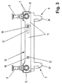
- Fig. 3 shows a sectional view with a view of the connection carrier 10 according to the Section line in Fig. 2.
- the connecting elements 11 of each connecting bracket 10 are each provided with an elongated hole 12 and a circular opening 13 and are on the side to each other so that an elongated hole 12 is opposite a circular opening 13.
- By the circular openings 13 of the two connection carriers 10 are transverse to their Longitudinal direction, that is, parallel to the side members 4, articulated bolt 16 inserted and axially secured so that the two connecting elements 11 each Connection carrier 10 guided longitudinally freely against each other by means of the elongated holes 12 are longitudinally displaceable.
- the connection carrier 10 further point to the outer ends of a through opening 15 through which the Is inserted through the side member tube; the fixation 8 takes place.
- a hinge parallelogram (not shown) is at the bottom of the hinge pin 16 and above hinged to a support unit (also not shown).
- the two parallel ones are each in a horizontal Flat side member 4 when placed on the container by the Dead weight of the carrying unit pushed apart synchronously.
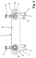
- Fig. 4 and Fig. 5 show the cross member 3, each of two by means of Laser cutting method easily produced cross support plates 19 (see FIG. 2) are. As can be seen in FIGS. 4 and 5, each cross member plate 19 has two Hook elements 17, the hook tips 18 of which point in the same direction.
- the one-piece design of the cross member plate 19 has the advantage that it is stable and is easy to manufacture.
- each cross member plate 19 has a Elongated hole 20 and a circular opening 21 provided in the longitudinal direction are spaced.
- the longitudinal displacement of the two cross member sheets 19 is thereby ensuring that in each cross member 19 each transverse to the longitudinal direction one of the bolts 5 of the side members 4 rotatably through the opening 21 (FIGS. 4 and 5, 4) and then passed through the elongated hole 20 is, or in reverse order.
- This arrangement is like FIGS. 4 and 5 show on both sides, but the elongated hole 20 is once from and once rear arranged.
- the two cross member sheets 19 are left with a small gap (approx. 0.1 mm) slidably connected to each other.
- each gripping element 6 is made of two in the exemplary embodiment Hook elements 17 formed, the two hook elements 17 each Gripping elements 6 belong to different cross member sheets 19.
- the two Hook elements 17 of each gripping element 6 face away from each other. They form in pushed together state (s. Fig. 4) - seen transversely to the longitudinal direction - itself tapering, insertable into the container opening 22, wherein the Hook tips 18 not over the outer contour of the other hook element 17 protrude, but cover the hook tip 18 each.
- the gripping elements 6 of each pair are therefore in opposite directions to each other along the cross member 3 can be moved synchronously.
- the hook elements 17 reach under after being completely immersed in the Container opening in the pushed apart state in the Container side wall formed web (not shown). Sliding apart takes place until the hook element shaft 23 strikes the container opening, at the same time the bolts 5 in the elongated holes at the corresponding end Plant come.
- the lower end is one of the two hook elements each Gripping elements 6 provided with a nose 24, which the narrow gap between the covers two directly opposite hook elements 17, so that there is no penetration of thin container walls, ribs or webs between two hook elements 17 when placed incorrectly on the container can come.
- the hook is simply bent through 90 ° in this area and then cut at an angle of 30 ° to the horizontal.
- the gripper 1 has in particular due to the two Hook elements 17 per gripping element 6 have a high gripping security.
- each crossmember plate 19 can also be used only with be provided with a single hook, in which case the two hook elements 17 of the Cross member 3 must be facing or facing away from each other.
Landscapes
- Engineering & Computer Science (AREA)
- Mechanical Engineering (AREA)
- Load-Engaging Elements For Cranes (AREA)
- Manipulator (AREA)
Abstract
Description
jedem von zwei Querträgem ein Paar Greifelemente zugeordnet ist. Die Greifelemente sind quer zur Hubrichtung verschiebbar.
Die Aufgabe der Erfindung ist es, einen konstruktiv einfachen Greifer zu schaffen, der aus wenigen kostengünstig herstellbaren Einzelteilen besteht.
Erfindungsgemäß ist jeder Querträger aus zwei längsverschiebbaren
Querträgerblechen gebildet und ist an jedem Querträgerblech jeweils ein Greifelement des Paares angeordnet, so dass die Greifelemente jedes Paares gegenläufig zueinander längs des Querträgers verschiebbar sind. Der Vorteil dieser Lösung besteht darin, daß die Querträgerbleche in nahezu beliebiger Kontur leicht und kostengünstig herstellbar sind.
Die Konstruktion des Greifers läßt sich weiter vereinfachen, wenn die Länge der beiden Querträger zur Bewegung der Greifelemente in ihre Greif- und Bereitschaftsstellung synchron veränderbar ist. Die Greifelemente sind hierbei fest an den Querträgern befestigt.
- Fig. 1
- eine perspektivische Ansicht eines Greifers,
- Fig. 2
- zwei Ansichten des Greifers gemäß Fig. 1,
- Fig. 3
- eine Schnittansicht gemäß der Schnittlinie in Fig. 2 mit Blick auf den Verbindungsträger,
- Fig. 4
- eine Seitenansicht des Greifers gemäß Fig. 1 mit zusammengeschobenen Hakenelementen und
- Fig. 5
- eine Seitenansicht des Greifers gemäß Fig. 1 mit auseinandergeschobenen Hakenelementen.
- 1
- Greifer
- 2
- Rahmen
- 3
- Querträger
- 4
- Längsträger
- 5
- Bolzen
- 6
- Greifelement
- 7
- Element
- 8
- Feststeller
- 9
- Durchgangsbohrung
- 10
- Verbindungsträger
- 11
- Verbindungselement
- 12
- Langloch
- 13
- Kreisöffnung
- 14
- Auflagerolle
- 15
- Durchgangsöffnung
- 16
- Gelenkbolzen
- 17
- Hakenelement
- 18
- Hakenspitze
- 19
- Querträgerblech
- 20
- Langloch
- 21
- kreisförmige Öffnung
- 22
- Einführelement
- 23
- Hakenelementschaft
- 24
- Nase
Claims (13)
- Greifer einer heb- und senkbaren Aufnahmevorrichtung für Behälter, mit einem von oben auf den Behälter aufsetzbaren Rahmen, mit an Querträgern des Rahmens angeordneten, sich nach unten erstreckenden und beim Aufsetzen in eine Behälteröffnung eintauchenden Greifelementen, die jeweils aus einer Bereitschaftsstellung in eine Greifstellung bewegbar sind und deren Abstand voneinander größer als die Greifelementabmessungen sind, wobei jeder Querträger (3) mindestens ein Paar Greifelemente (6) aufweist
dadurch gekennzeichnet,
daß jeder Querträger (3) aus zwei längsverschiebbaren Querträgerblechen (19) gebildet ist und daß an jedem Querträgerblech (19) jeweils ein Greifelement (6) des Paars angeordnet ist, so dass die Greifelemente (6) jedes Paars gegenläufig zueinander längs des Querträgers (3) verschiebbar sind. - Greifer nach Anspruch 1,
dadurch gekennzeichnet,
daß die Länge der beiden Querträger (3) zur Bewegung der Greifelemente (6) in ihre Greif- bzw. Bereitschaftsstellung synchron veränderbar ist. - Greifer nach Anspruch 1,
dadurch gekennzeichnet,
daß an jedem Querträgerblech (19) quer zur Längsrichtung ein Bolzen (5) in einer Kreisöffnung 13 und längsbeabstandet von diesem ein Langloch (20) vorgesehen ist, wobei der Bolzen (5) jeweils in das Langloch (20) des anderen Querträgerblechs (19) desselben Querträgers (3) eingreift. - Greifer nach einem der Ansprüche 1 oder 3,
dadurch gekennzeichnet,
daß jedes Greifelement (6) des Paars aus zwei Hakenelementen (17) gebildet ist, wobei das eine Hakenelement (17) an dem einen und das andere Hakenelement (17) an dem anderen Querträgerblech (19) angeordnet ist. - Greifer nach Anspruch 4,
dadurch gekennzeichnet,
daß die beiden Hakenelemente (17) jedes Greifelements (6) einander abgewandt sind. - Greifer nach einem der Ansprüche 4 oder 5,
dadurch gekennzeichnet,
daß die beiden auseinandergeschobenen Hakenelemente (17) jedes Greifelements (6) quer zur Längsrichtung gesehen einander überschneiden. - Greifer nach einem der Ansprüche 4 - 6
dadurch gekennzeichnet,
daß jedes Querträgerblech (19) und die zugehörigen Hakenelemente (17) einstückig ausgebildet sind. - Greifer nach einem der Ansprüche 4 - 7,
dadurch gekennzeichnet,
daß jedes Querträgerblech (19) und die zugehörigen Hakenelemente (17) aus einem Blech herausgeschnitten sind, insbesondere mittels des Laserschneidverfahrens. - Greifer nach einem der Ansprüche 4 - 8,
dadurch gekennzeichnet,
daß das untere Ende eines der beiden Hakenelemente (17) des Greifelements (6) so ausgebildet ist, daß deren Spalt abgedeckt ist. - Greifer nach einem der Ansprüche 4 - 9,
dadurch gekennzeichnet,
daß die beiden zusammengeschobenen Hakenelemente (17) jedes Greifelements (6) quer zur Längsrichtung gesehen einander derart abdecken, daß sie ein sich nach unten verjüngendes, in die Behälteröffnung einführbares Einführelement (22) bilden. - Greifer nach einem der Ansprüche 1 - 10,
dadurch gekennzeichnet,
daß der Rahmen (2) mit den Querträgern (3) verbundene Längsträger (4) aufweist, an deren Enden die Bolzen (5) angeordnet sind. - Greifer nach Anspruch 11,
dadurch gekennzeichnet,
daß die parallelen Längsträger (4) teleskopisch verschiebbar sind. - Greifer nach einem der Ansprüche 11 oder 12,
dadurch gekennzeichnet,
daß außen an den Bolzen (5) drehgelagerte Auflagerollen (14) zur Auflage auf dem Behälterrand aufgesteckt sind.
Applications Claiming Priority (2)
| Application Number | Priority Date | Filing Date | Title |
|---|---|---|---|
| DE19946122 | 1999-09-20 | ||
| DE19946122A DE19946122C2 (de) | 1999-09-20 | 1999-09-20 | Greifer einer heb- und senkbaren Aufnahmevorrichtung für von oben zu greifende Behälter |
Publications (2)
| Publication Number | Publication Date |
|---|---|
| EP1084979A1 true EP1084979A1 (de) | 2001-03-21 |
| EP1084979B1 EP1084979B1 (de) | 2004-02-18 |
Family
ID=7923364
Family Applications (1)
| Application Number | Title | Priority Date | Filing Date |
|---|---|---|---|
| EP00250288A Expired - Lifetime EP1084979B1 (de) | 1999-09-20 | 2000-08-30 | Greifer einer heb- und senkbaren Aufnahmevorrichtung für von oben zu greifende Behälter |
Country Status (4)
| Country | Link |
|---|---|
| US (1) | US6471274B1 (de) |
| EP (1) | EP1084979B1 (de) |
| JP (1) | JP2001129781A (de) |
| DE (2) | DE19946122C2 (de) |
Cited By (3)
| Publication number | Priority date | Publication date | Assignee | Title |
|---|---|---|---|---|
| US7618479B2 (en) | 2004-04-14 | 2009-11-17 | Mann & Hummel Gmbh | Adsorber for adsorbing hydrocarbon vapors from return flows through an intake tract of an internal combustion engine |
| WO2010112231A1 (de) | 2009-04-03 | 2010-10-07 | Sms Siemag Ag | Traverse |
| CN115490133A (zh) * | 2022-11-14 | 2022-12-20 | 四川航天系统工程研究所 | 一种多规格负载质心调整装置 |
Families Citing this family (9)
| Publication number | Priority date | Publication date | Assignee | Title |
|---|---|---|---|---|
| AUPO289296A0 (en) * | 1996-10-10 | 1996-10-31 | Securency Pty Ltd | Self-verifying security documents |
| JP4533094B2 (ja) * | 2004-11-10 | 2010-08-25 | サントリーホールディングス株式会社 | 樽状容器用吊り下げ搬送装置 |
| RU2291100C1 (ru) * | 2005-06-01 | 2007-01-10 | Общество с ограниченной ответственностью "Специальное конструкторское технологическое бюро" (ООО "СКТБ") | Захватное устройство для контейнеров с фитингами |
| CN100418709C (zh) * | 2005-12-27 | 2008-09-17 | 中国科学院沈阳自动化研究所 | 一种强作业型水下机器人用可移动起吊点结构 |
| GB2510878A (en) * | 2013-02-18 | 2014-08-20 | Terra Roadways Ltd Fa | A crane grab head |
| JP6756415B2 (ja) * | 2018-03-12 | 2020-09-16 | 日立化成株式会社 | 保持装置及び鋳造部材製造装置 |
| KR102395115B1 (ko) * | 2019-04-12 | 2022-05-09 | 김희영 | 카트리지 이송보조장치 |
| GB202019712D0 (en) * | 2020-12-14 | 2021-01-27 | Ocado Innovation Ltd | Gripping device |
| CN112853999B (zh) * | 2021-02-05 | 2022-09-30 | 泰州职业技术学院 | 一种桥梁施工用防撞护栏用吊具 |
Citations (5)
| Publication number | Priority date | Publication date | Assignee | Title |
|---|---|---|---|---|
| US2597128A (en) * | 1947-06-10 | 1952-05-20 | Arthur O Reinking | Bottle handling device |
| FR1487616A (fr) * | 1965-07-23 | 1967-07-07 | Dispositif pour saisir et déplacer des récipients | |
| DE4229346A1 (de) * | 1991-09-04 | 1993-03-11 | Heinz Schmidt | Vertikalgreifer fuer systembehaelter |
| DE4304723A1 (en) * | 1992-02-17 | 1993-08-19 | Heinz Schmidt | Lifting grab for containers of different sizes - has centring members adjustable horizontally to suit container width and sliding claw mechanism |
| DE29516996U1 (de) * | 1995-09-28 | 1996-04-11 | Ainedter, Dieter, Dipl.-Ing., Salzburg | Portal-Krananlage zum Anheben und Transportieren von mit Gitterträgern oder vorstehenden Greifbügeln versehenen Betonplatten und Eingriffselement zum Erfassen der Gitterträger oder Greifbügel |
Family Cites Families (6)
| Publication number | Priority date | Publication date | Assignee | Title |
|---|---|---|---|---|
| US3302968A (en) * | 1965-09-29 | 1967-02-07 | Rca Corp | Gripper bar |
| US3727965A (en) * | 1971-07-12 | 1973-04-17 | Cranston Machiner Co Inc | Lifting tool for bound packages |
| US3762754A (en) * | 1971-09-13 | 1973-10-02 | Clark Equipment Co | Universal coupling means for container handling |
| AT391459B (de) * | 1989-04-04 | 1990-10-10 | Sticht Fertigungstech Stiwa | Einrichtung zum handhaben von bauteilen mit einer greifvorrichtung |
| DE4229215A1 (de) | 1991-09-04 | 1993-03-11 | Heinz Schmidt | Vertikalgreifer mit transportsicherung |
| WO1997030928A1 (en) * | 1996-02-21 | 1997-08-28 | Hyco-Cascade Pty. Ltd. | Container handling assembly |
-
1999
- 1999-09-20 DE DE19946122A patent/DE19946122C2/de not_active Expired - Fee Related
-
2000
- 2000-08-30 EP EP00250288A patent/EP1084979B1/de not_active Expired - Lifetime
- 2000-08-30 DE DE50005311T patent/DE50005311D1/de not_active Expired - Lifetime
- 2000-09-13 US US09/660,801 patent/US6471274B1/en not_active Expired - Fee Related
- 2000-09-20 JP JP2000284618A patent/JP2001129781A/ja active Pending
Patent Citations (5)
| Publication number | Priority date | Publication date | Assignee | Title |
|---|---|---|---|---|
| US2597128A (en) * | 1947-06-10 | 1952-05-20 | Arthur O Reinking | Bottle handling device |
| FR1487616A (fr) * | 1965-07-23 | 1967-07-07 | Dispositif pour saisir et déplacer des récipients | |
| DE4229346A1 (de) * | 1991-09-04 | 1993-03-11 | Heinz Schmidt | Vertikalgreifer fuer systembehaelter |
| DE4304723A1 (en) * | 1992-02-17 | 1993-08-19 | Heinz Schmidt | Lifting grab for containers of different sizes - has centring members adjustable horizontally to suit container width and sliding claw mechanism |
| DE29516996U1 (de) * | 1995-09-28 | 1996-04-11 | Ainedter, Dieter, Dipl.-Ing., Salzburg | Portal-Krananlage zum Anheben und Transportieren von mit Gitterträgern oder vorstehenden Greifbügeln versehenen Betonplatten und Eingriffselement zum Erfassen der Gitterträger oder Greifbügel |
Cited By (3)
| Publication number | Priority date | Publication date | Assignee | Title |
|---|---|---|---|---|
| US7618479B2 (en) | 2004-04-14 | 2009-11-17 | Mann & Hummel Gmbh | Adsorber for adsorbing hydrocarbon vapors from return flows through an intake tract of an internal combustion engine |
| WO2010112231A1 (de) | 2009-04-03 | 2010-10-07 | Sms Siemag Ag | Traverse |
| CN115490133A (zh) * | 2022-11-14 | 2022-12-20 | 四川航天系统工程研究所 | 一种多规格负载质心调整装置 |
Also Published As
| Publication number | Publication date |
|---|---|
| US6471274B1 (en) | 2002-10-29 |
| DE50005311D1 (de) | 2004-03-25 |
| DE19946122A1 (de) | 2001-04-26 |
| JP2001129781A (ja) | 2001-05-15 |
| DE19946122C2 (de) | 2001-08-02 |
| EP1084979B1 (de) | 2004-02-18 |
Similar Documents
| Publication | Publication Date | Title |
|---|---|---|
| EP1754897B1 (de) | Lagerungsvorrichtung | |
| DE69929670T2 (de) | Schubgliederkette für Lasten | |
| EP0116281B1 (de) | Anbaugerät für verfahrbare Stapler in der Form eines Zinkenverstellgerätes mit Seitenschub und vier Zinken | |
| DE2922420C2 (de) | ||
| DE19901496C1 (de) | Klemmgreifer für von oben zu greifende Lasten | |
| DE2525866A1 (de) | Gestell fuer aufgestapelte bleche | |
| EP1084979B1 (de) | Greifer einer heb- und senkbaren Aufnahmevorrichtung für von oben zu greifende Behälter | |
| EP2953887B1 (de) | Vorrichtung zur aufnahme und zum transport von lasten | |
| DE1781058B1 (de) | Hublader mit querschiebbarem rahmenfuer lasttraeger am hubschlitten | |
| EP4397566B1 (de) | Lastbeförderungsvorrichtung | |
| EP3290264B1 (de) | Transportwagen | |
| DE69209733T2 (de) | Einsperrgitter | |
| DE2943274C2 (de) | Stapelsicherung, bestehend aus wenigstens einer an einer vertikalen Stapelkante anliegenden Winkelschiene | |
| DE3712657C2 (de) | ||
| EP3538454B1 (de) | Vorrichtung zur unterteilung einer fläche in teilflächen | |
| DE3132952C2 (de) | Wendevorrichtung, insbesondere für Paletten | |
| DE2813762A1 (de) | Vorrichtung zum zuschneiden von platten | |
| DE2755651A1 (de) | Aufsatzgeraet fuer gabelstaplerfahrzeuge | |
| DE2308487A1 (de) | Halterung fuer lasthandhaben an hubfahrzeugen | |
| EP1066774B1 (de) | Lagerregal | |
| DE19618212A1 (de) | Handhabungsvorrichtung | |
| DE1781058C (de) | Hublader mit querschiebbarem Rahmen fur Lastträger am Hubschlitten | |
| DE2049286C3 (de) | Regal | |
| DE1807629C (de) | Hubmast für Hublader | |
| DE1402118C (de) | Abkantmatrize |
Legal Events
| Date | Code | Title | Description |
|---|---|---|---|
| PUAI | Public reference made under article 153(3) epc to a published international application that has entered the european phase |
Free format text: ORIGINAL CODE: 0009012 |
|
| AK | Designated contracting states |
Kind code of ref document: A1 Designated state(s): CH DE ES FR GB IT LI |
|
| AX | Request for extension of the european patent |
Free format text: AL;LT;LV;MK;RO;SI |
|
| 17P | Request for examination filed |
Effective date: 20010308 |
|
| AKX | Designation fees paid |
Free format text: CH DE ES FR GB IT LI |
|
| GRAP | Despatch of communication of intention to grant a patent |
Free format text: ORIGINAL CODE: EPIDOSNIGR1 |
|
| GRAS | Grant fee paid |
Free format text: ORIGINAL CODE: EPIDOSNIGR3 |
|
| RAP1 | Party data changed (applicant data changed or rights of an application transferred) |
Owner name: DEMAG CRANES & COMPONENTS GMBH |
|
| GRAA | (expected) grant |
Free format text: ORIGINAL CODE: 0009210 |
|
| AK | Designated contracting states |
Kind code of ref document: B1 Designated state(s): CH DE ES FR GB IT LI |
|
| REG | Reference to a national code |
Ref country code: GB Ref legal event code: FG4D Free format text: NOT ENGLISH |
|
| REG | Reference to a national code |
Ref country code: CH Ref legal event code: EP |
|
| REF | Corresponds to: |
Ref document number: 50005311 Country of ref document: DE Date of ref document: 20040325 Kind code of ref document: P |
|
| PG25 | Lapsed in a contracting state [announced via postgrant information from national office to epo] |
Ref country code: ES Free format text: LAPSE BECAUSE OF FAILURE TO SUBMIT A TRANSLATION OF THE DESCRIPTION OR TO PAY THE FEE WITHIN THE PRESCRIBED TIME-LIMIT Effective date: 20040529 |
|
| GBT | Gb: translation of ep patent filed (gb section 77(6)(a)/1977) |
Effective date: 20040520 |
|
| PG25 | Lapsed in a contracting state [announced via postgrant information from national office to epo] |
Ref country code: CH Free format text: LAPSE BECAUSE OF NON-PAYMENT OF DUE FEES Effective date: 20040831 Ref country code: LI Free format text: LAPSE BECAUSE OF NON-PAYMENT OF DUE FEES Effective date: 20040831 |
|
| ET | Fr: translation filed | ||
| PLBE | No opposition filed within time limit |
Free format text: ORIGINAL CODE: 0009261 |
|
| STAA | Information on the status of an ep patent application or granted ep patent |
Free format text: STATUS: NO OPPOSITION FILED WITHIN TIME LIMIT |
|
| 26N | No opposition filed |
Effective date: 20041119 |
|
| REG | Reference to a national code |
Ref country code: CH Ref legal event code: PL |
|
| PGFP | Annual fee paid to national office [announced via postgrant information from national office to epo] |
Ref country code: DE Payment date: 20140821 Year of fee payment: 15 |
|
| PGFP | Annual fee paid to national office [announced via postgrant information from national office to epo] |
Ref country code: FR Payment date: 20140821 Year of fee payment: 15 Ref country code: GB Payment date: 20140820 Year of fee payment: 15 |
|
| PGFP | Annual fee paid to national office [announced via postgrant information from national office to epo] |
Ref country code: IT Payment date: 20140827 Year of fee payment: 15 |
|
| REG | Reference to a national code |
Ref country code: DE Ref legal event code: R119 Ref document number: 50005311 Country of ref document: DE |
|
| GBPC | Gb: european patent ceased through non-payment of renewal fee |
Effective date: 20150830 |
|
| PG25 | Lapsed in a contracting state [announced via postgrant information from national office to epo] |
Ref country code: IT Free format text: LAPSE BECAUSE OF NON-PAYMENT OF DUE FEES Effective date: 20150830 |
|
| REG | Reference to a national code |
Ref country code: FR Ref legal event code: ST Effective date: 20160429 |
|
| PG25 | Lapsed in a contracting state [announced via postgrant information from national office to epo] |
Ref country code: GB Free format text: LAPSE BECAUSE OF NON-PAYMENT OF DUE FEES Effective date: 20150830 Ref country code: DE Free format text: LAPSE BECAUSE OF NON-PAYMENT OF DUE FEES Effective date: 20160301 |
|
| PG25 | Lapsed in a contracting state [announced via postgrant information from national office to epo] |
Ref country code: FR Free format text: LAPSE BECAUSE OF NON-PAYMENT OF DUE FEES Effective date: 20150831 |