EP1084980A1 - Wagen, vorzugsweise Kran-Laufkatze - Google Patents
Wagen, vorzugsweise Kran-Laufkatze Download PDFInfo
- Publication number
- EP1084980A1 EP1084980A1 EP00119929A EP00119929A EP1084980A1 EP 1084980 A1 EP1084980 A1 EP 1084980A1 EP 00119929 A EP00119929 A EP 00119929A EP 00119929 A EP00119929 A EP 00119929A EP 1084980 A1 EP1084980 A1 EP 1084980A1
- Authority
- EP
- European Patent Office
- Prior art keywords
- wheel axles
- track
- trolley
- carriage according
- frame
- Prior art date
- Legal status (The legal status is an assumption and is not a legal conclusion. Google has not performed a legal analysis and makes no representation as to the accuracy of the status listed.)
- Granted
Links
Images




Classifications
-
- B—PERFORMING OPERATIONS; TRANSPORTING
- B66—HOISTING; LIFTING; HAULING
- B66C—CRANES; LOAD-ENGAGING ELEMENTS OR DEVICES FOR CRANES, CAPSTANS, WINCHES, OR TACKLES
- B66C9/00—Travelling gear incorporated in or fitted to trolleys or cranes
- B66C9/06—Travelling gear incorporated in or fitted to trolleys or cranes for more than one rail gauge
Definitions
- the invention relates to a carriage, preferably a crane trolley, with a Device for driving from a wider and a narrower, from each other parallel girders or rails existing track, preferably for driving the lower corner straps forming the rails of an outer boom part and one from this telescopic inner boom part, which from static closed three- or four-belt systems exist.
- a cantilever arm that is not documented in print is known from practice from an outer, cross-sectionally U-shaped open at the bottom Cantilever part and an inner, from this telescopic boom part, which has a triangular cross-section, the upper side Corner belts are guided in guides of the outer boom part and with the middle lower belt side guide rails are connected in such a way that Double trolley wheel sets projecting upwards always with one wheel each either run on guide rails that are on the inside of the lower leg of the outer support part or on both sides of the middle lower belt of the extendable boom part are arranged.
- This well-known boom construction is, however, disadvantageous in that the outer U-shaped boom part is due to its profile has only a relatively low strength.
- the object of the invention is therefore to provide a trolley or a crane trolley to create the type specified at the outset, which is an automatic and secure It is possible to change lanes at full speed even if those forming the lanes Carrier or rails Parts of statically closed three or four belt systems are.
- this object is achieved in that on the frame of the Wagens two opposing wheels, which from the outside Reach over carriers of the wider track, and two more opposite each other Wheels are stored, which are the carriers of the narrower from the outside Overlap the track and its overhung axially supported axially and by a shifting device into its active position inwards and in theirs inactive position are displaceable to the outside.
- the car according to the invention or the crane trolley according to the invention runs hanging on the side lower straps of a supporting structure or a jib, that of a statically closed three or four belt system in the usual lattice construction consists.
- the trolley runs on the lower belts of a boom link only carry the four wheels that are rotatable on rigid axles of the frame are stored. However, the trolley passes over the connection area between the outer and the telescoped inner boom part, the four on the slidable axles mounted wheels towards each other so that they run on the side lower chords of the outer boom section and that of wheels running down the lower belts of the outer boom part and are inoperative.
- the displacement device preferably consists of the displaceable wheel axles springs shifting to their extended positions, e.g. Compression springs, with guides provided between the tracks of different widths are on which sliding blocks connected to the movable wheel axles or run rolls.
- the springs load those that can be moved in the axial direction Wheel axles in their extended positions, so that the wheel axles pushed together on the narrower track when the over the guides running rollers or sliding blocks a corresponding pushing the Allow wheel axles on the narrower track.
- the movable ones Wheel axles when the trolley returns through those running over the guides Sliding blocks or rollers are moved back to their inactive position.
- pins connected to the displaceable wheel axles are in the transition area of the tracks in with the carriers of the wider track connected guides that move the wheel axles between the gauges.
- the movable Wheel axles are provided with anti-rotation locks that protect against frame-fixed Support abutment.
- the anti-rotation devices can be angled Carrier exist, one leg with a groove or an elongated hole frame-fixed sliding block or a role.
- the side sliding blocks or rollers are advantageously in the angled Carrier arranged.
- the movable Wheel axles are spring-loaded support levers that are connected to each other to the extended position of the wheel axles against frame-fixed abutments can put on, ineffective when the wheel axles are retracted support the abutments and between their active and ineffective positions are pivoted.
- These support levers prevent that when moving the trolley on the narrower track through this lateral forces acting on the trolley laterally against the action of the springs can be pushed away.
- lateral forces act on the trolley supports the pivoted support lever against the frame-fixed abutment of the trolley from, so that a lateral emigration or swimming prevents the trolley is.
- the movable axes rotatably mounted rollers with respect to the through the Impellers defined running levels are higher than those on the fixed axles Casters. This configuration ensures that the axially The castors with movable axes are not on the one that defines the wider track lower straps of the outer boom part run so that an undesirable, statically indefinite running of all wheels on the lower belts of the outer boom part is avoided.
- rollers are mounted, which are against the outer sides or edges the bearer of the wider track can put on. These rollers support the Wagon or trolley against lateral forces if this on the wider Run track.
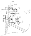
- FIG. 1 is a front view of a two-part boom of a tower crane can be seen, which consists of an outer boom part 1 and an inner boom part 2 consists of the outer boom part 1 telescopic and in this again is retractable.
- the guidance of the telescopic inner boom part 1 in the outer is known per se and is therefore not explained in more detail here.
- Both boom parts 1, 2 consist of conventional lattice girders consisting of closed Three belt systems with belt braces stiffening the corners.
- the lower Belt carrier 3, 4 of the outer boom part 1 and 5, 6 of the inner boom part 2 serve in the usual way as rails for the roles of the crane trolley 7.
- the trolley 7 is supported with its Impellers on the lower chords 3, 4 of the outer boom part 2.
- the trolley 7 consists of a base frame, whose side supports 8, 9 in their central areas with down projecting support pieces 10, 11 are provided, which by a cross member 13 to the Trolley support frames are connected.
- On the side frame bars 8, 9 are attached two pairs of rollers, namely rollers 14, the axes 15 in the side rails 8, 9 welded sockets 16 immovable and are held non-rotatably and on their freely projecting pins on roller bearings the rollers 14 are mounted.
- These rollers 14 run on the top Treads of the lower straps 3, 4 of the outer boom part 1.
- the upstanding leg 27 of an angled support 28 is welded, the for this purpose is provided with a bore into which the axis 22 in the Fig. 4 is clearly inserted.
- the right angle of the leg 27 angled leg 29 of the carrier 28 runs parallel to the axis 22 and is provided with an elongated hole 30 in which a sliding block 31 is slidably guided the bracket 32 welded to the frame member 8 of the trolley frame is.
- the sliding block 31 slidably guided in the slot 30 thus serves as an anti-rotation device for axis 22.
- journal 34 On the leg 29 of the support 28 there is a journal in the area of the bend 34 welded, which is perpendicular to the axis 22. On this journal 34, a roller 35 is mounted, each on the vertical outer sides the corner straps 3, 5 of the boom parts 1, 2 amounts.
- the bearing legs for a flap-shaped Form lever 36 which is about an axis parallel to the frame spar 8 37 is pivotally mounted on the sheets 35.
- the lever 36 is a two-armed Lever formed, the lever arm 38 by a leg spring in the direction is applied to a block 40 forming an abutment, which in the from the 5 and 6 evident way with the frame spar 8 of the support frame Trolley is welded.
- the inwardly projecting lever arm 42 of the lever 36 is formed as a bearing axis on which a roller 43 is freely rotatable.
- This roller 43 interacts with a curve guide 45 (FIGS. 2 and 5) that in the transition area between the outer and the inner boom part on the outer boom part 1 is attached. If the trolley 7 passes this curve 45, it will the inner lever arm 42 via the roller 43 in the manner shown in FIG. 5 pressed down so that the outer, longer lever arm 38 over the abutment 40 is pivoted out.
- a curve guide 45 FIGS. 2 and 5
- the trolley 7 passes over the curve 45 in the direction of the inner, from the outer Cantilevered boom part 2, pivots the leg spring 30 after the roller 43 has run off the curve 45, the lever arm 38 in FIG. 7 apparent manner on the frame spar 8 such that the one abutting surface Front side of the lever arm 38 lies in front of the abutment 40 and thus against that Abutment 40 abuts when lateral forces act on the trolley against the action of the compression springs 23 to move laterally.
- Fig. 9 shows a side view and a plan view of the belt carrier 3 and 5 of the outer and inner boom part at a time when the leading Wheels 14 of the trolley 7 straight from the belt carriers forming a wider track of the outer boom section and the leading axially displaceable Rollers 25 already pushed together on the narrower track of the inner boom part are and straight on the treads 3, 4 of the narrower Put the track down.
- the left part of FIG. 9 run on the Treads of the belt carrier 3, 4 of the outer boom part 1 only on the rigid Axle-mounted impellers 14, while the axially displaceable impellers 25 are out of engagement with the treads because they are on a higher level.
- Fig. 10 shows the wheels of the trolley in a state in which the front Impellers the connection area between the outer and inner boom part have already run over.
- the wheels 25 run on the through the treads the belt carrier 5, 6 formed narrower track.
- the trailing wheels 14 are freely suspended outside of the treads Track.
Landscapes
- Engineering & Computer Science (AREA)
- Mechanical Engineering (AREA)
- Jib Cranes (AREA)
- Carriers, Traveling Bodies, And Overhead Traveling Cranes (AREA)
- Handcart (AREA)
Abstract
Description
- Fig. 1
- die Vorderansicht eines Kranauslegers, bestehend aus einem äußeren Auslegerteil, in dem ein inneres Auslegerteil austeleskopierbar und einziehbar geführt ist, mit einer auf den unteren seitlichen Gurten des äußeren Auslegerteils laufenden Laufkatze,
- Fig. 2
- eine Seitenansicht des Auslegers mit Laufkatze nach Fig. 1,
- Fig. 3
- eine Draufsicht auf den Ausleger und die Laufkatze nach den Fig. 1 und 2, wobei von den Auslegern der besseren Übersichtlichkeit halber nur die Untergurte dargestellt sind,
- Fig. 4
- einen Horizontalschnitt durch einen Radsatz der Laufkatze,
- Fig. 5
- einen vergrößerten Ausschnitt aus Fig. 1,
- Fig. 6
- eine der Fig. 5 entsprechende Darstellung, in der das Laufrad und die Laufradachse geschnitten dargestellt sind,
- Fig. 7
- eine der Fig. 5 entsprechende Darstellung, in der die axial verschieblichen Laufradachsen auf die schmalere Spur zusammengefahren sind,
- Fig. 8
- eine der Fig. 7 entsprechende Darstellung, in der das Laufrad und die Laufradachse geschnitten dargestellt sind,
- Fig. 9
- eine Draufsicht und eine zugehörige Seitenansicht der Laufräder vor dem Auflauf der verschieblichen Laufräder auf die schmalere Spur in schematischer Darstellung und
- Fig. 10
- eine der Fig. 9 entsprechende Darstellung, in der die Räder der vorderen verschieblichen Achsen auf die Gurte der schmaleren Spur aufgelaufen sind.
Claims (9)
- Wagen, vorzugsweise Kran-Laufkatze (7), mit einer Einrichtung zum Befahren von einer breiteren und einer schmaleren, aus zueinander parallelen Trägern oder Schienen bestehenden Spur, vorzugsweise zum Befahren der Schienen bildenden unteren Eckgurte (2, 4; 5, 6) eines äußeren Auslegerteils (1) und eines aus diesem aus- und in diesen einteleskopierbaren inneren Auslegerteils (2), die aus statisch geschlossenen Drei- oder Viergurtsystemen bestehen,
dadurch gekennzeichnet,
daß an dem Rahmen (8, 9, 10, 11, 13) des Wagens (7) jeweils zwei einander gegenüberliegende Laufräder (14), die von außen her die Träger der breiteren Spur (3, 4) übergreifen, und jeweils zwei weitere einander gegenüberliegende Laufräder (25) gelagert sind, die von außen her die Träger der schmaleren Spur (5, 6) übergreifen und deren fliegend gelagerten Achsen (22) axial verschieblich gelagert und durch eine Verschiebeeinrichtung in ihre aktive Stellung nach innen und ihre inaktive Stellung nach außen verschieblich sind. - Wagen nach Anspruch 1, dadurch gekennzeichnet, daß die Verschiebeeinrichtung aus die verschieblichen Radachsen (22) in ihre aufeinander zu ausgefahrene Stellung verschiebenden Federn (23), z.B. Druckfedern, bestehen, und daß Führungen zwischen den unterschiedlich breiten Spuren vorgesehen sind, auf denen mit den verschieblichen Radachsen verbundene Gleitsteine oder Rollen (35) laufen.
- Wagen nach Anspruch 1 oder 2, dadurch gekennzeichnet, daß mit den verschieblichen Radachsen (22) Zapfen (50) verbunden sind, die im Übergangsbereich der Spuren in mit den Trägern (3, 4) der breiteren Spur verbundenen Führungen (55) greifen, die die Radachsen zwischen den Spurweiten verschieben.
- Wagen nach einem der Ansprüche 1 bis 3, dadurch gekennzeichnet, daß die verschieblichen Radachsen (22) mit Verdrehsicherungen versehen sind, die sich gegen rahmenfeste Widerlager (31) abstützen.
- Wagen nach Anspruch 4, dadurch gekennzeichnet, daß die Verdrehsicherung aus einem abgewinkelten Träger (28) besteht, dessen einer Schenkel (29) mit einer Nut oder einem Langloch (30) einen rahmenfesten Gleitstein (31) oder eine Rolle einfaßt.
- Wagen nach einem der Ansprüche 1 bis 5, dadurch gekennzeichnet, daß die seitlichen Gleitsteine oder Rollen (35) an dem abgewinkelten Träger (28) angeordnet sind.
- Wagen nach einem der Ansprüche 1 bis 6, dadurch gekennzeichnet, daß mit den verschieblichen Radachsen (22) federbelastete Stützhebel (36) verbunden sind, die sich in der aufeinander zu ausgefahrenen Stellung der Radachsen (22) gegen rahmenfeste Widerlager (40) anlegen können, sich im eingefahrenen Zustand der Radachsen (22) wirkungslos auf den Widerlagern (40) aufruhen und durch spurfeste Führungskurven (45) zwischen ihren aktiven und wirkungslosen Stellungen verschwenkt werden.
- Wagen nach einem der Ansprüche 1 bis 7, dadurch gekennzeichnet, daß die an den verschieblichen Achsen (22) drehbar gelagerten Laufräder (25) in Bezug auf deren Laufebenen höher liegen als die an festen Achsen (15) gelagerten Laufräder (14).
- Wagen nach einem der Ansprüche 1 bis 8, dadurch gekennzeichnet, daß an dem Rahmen um zu den Laufräder (14, 25) rechtwinkelige Achsen Stützrollen (18) gelagert sind, die sich gegen die außen liegenden Seiten oder Kanten der Traggurte (3, 4) der breiteren Spur anlegen können.
Applications Claiming Priority (2)
| Application Number | Priority Date | Filing Date | Title |
|---|---|---|---|
| DE29916416U DE29916416U1 (de) | 1999-09-17 | 1999-09-17 | Wagen, vorzugsweise Kran-Laufkatze |
| DE29916416U | 1999-09-17 |
Publications (2)
| Publication Number | Publication Date |
|---|---|
| EP1084980A1 true EP1084980A1 (de) | 2001-03-21 |
| EP1084980B1 EP1084980B1 (de) | 2004-12-08 |
Family
ID=8079082
Family Applications (1)
| Application Number | Title | Priority Date | Filing Date |
|---|---|---|---|
| EP00119929A Expired - Lifetime EP1084980B1 (de) | 1999-09-17 | 2000-09-13 | Wagen, vorzugsweise Kran-Laufkatze |
Country Status (4)
| Country | Link |
|---|---|
| EP (1) | EP1084980B1 (de) |
| AT (1) | ATE284366T1 (de) |
| DE (2) | DE29916416U1 (de) |
| ES (1) | ES2232366T3 (de) |
Cited By (1)
| Publication number | Priority date | Publication date | Assignee | Title |
|---|---|---|---|---|
| EP1512660A1 (de) * | 2003-09-02 | 2005-03-09 | Liebherr-Werk Biberach GmbH | Kran mit Laufkatze |
Families Citing this family (1)
| Publication number | Priority date | Publication date | Assignee | Title |
|---|---|---|---|---|
| DE10022658B4 (de) | 1999-06-28 | 2007-10-04 | Terex-Demag Gmbh & Co. Kg | Teleskopkran |
Citations (7)
| Publication number | Priority date | Publication date | Assignee | Title |
|---|---|---|---|---|
| FR2193773A1 (de) * | 1972-07-26 | 1974-02-22 | Liebherr Hans | |
| FR2211393A1 (de) * | 1972-12-27 | 1974-07-19 | Pingon Pierre Joseph | |
| FR2235078A1 (en) * | 1973-06-29 | 1975-01-24 | Cadillon Roger | Telescopic crane jib - has at least two telescoping open structure members for transporting jib in compact form |
| FR2338889A1 (fr) * | 1976-01-22 | 1977-08-19 | Cattaneo Ambrogio | Dispositif pour le deplacement d'un chariot le long d'une fleche de grue comprenant au moins deux troncons mobiles telescopiquement l'un par rapport a l'autre |
| FR2346277A1 (fr) * | 1976-04-02 | 1977-10-28 | Potain Sa | Perfectionnements pour une fleche telescopique de grue equipee d'un chariot distributeur |
| LU85761A1 (fr) * | 1985-02-06 | 1986-09-02 | Fiordiligi Societe Anonyme | Fleche telescopique d'une grue a tour ou analogue |
| EP0204383A1 (de) * | 1985-06-05 | 1986-12-10 | Fiordiligi S.A. | Teleskopausleger eines Krans oder dergleichen |
Family Cites Families (3)
| Publication number | Priority date | Publication date | Assignee | Title |
|---|---|---|---|---|
| DE7019616U (de) | 1970-05-26 | 1970-11-05 | Demag Ag | Laufkatze, insbesondere unterflansch-haengekatze. |
| FR2236770A1 (en) | 1973-07-03 | 1975-02-07 | Rock Sa | Tower crane telescopic jib crab - has stepped rollers for continuous running on rails of different gauge |
| US3870163A (en) | 1973-12-27 | 1975-03-11 | Pierre Joseph Pingon | Telescopic boom and carriage with shiftable wheels therefor |
-
1999
- 1999-09-17 DE DE29916416U patent/DE29916416U1/de not_active Expired - Lifetime
-
2000
- 2000-09-13 AT AT00119929T patent/ATE284366T1/de active
- 2000-09-13 DE DE2000508893 patent/DE50008893D1/de not_active Expired - Lifetime
- 2000-09-13 ES ES00119929T patent/ES2232366T3/es not_active Expired - Lifetime
- 2000-09-13 EP EP00119929A patent/EP1084980B1/de not_active Expired - Lifetime
Patent Citations (7)
| Publication number | Priority date | Publication date | Assignee | Title |
|---|---|---|---|---|
| FR2193773A1 (de) * | 1972-07-26 | 1974-02-22 | Liebherr Hans | |
| FR2211393A1 (de) * | 1972-12-27 | 1974-07-19 | Pingon Pierre Joseph | |
| FR2235078A1 (en) * | 1973-06-29 | 1975-01-24 | Cadillon Roger | Telescopic crane jib - has at least two telescoping open structure members for transporting jib in compact form |
| FR2338889A1 (fr) * | 1976-01-22 | 1977-08-19 | Cattaneo Ambrogio | Dispositif pour le deplacement d'un chariot le long d'une fleche de grue comprenant au moins deux troncons mobiles telescopiquement l'un par rapport a l'autre |
| FR2346277A1 (fr) * | 1976-04-02 | 1977-10-28 | Potain Sa | Perfectionnements pour une fleche telescopique de grue equipee d'un chariot distributeur |
| LU85761A1 (fr) * | 1985-02-06 | 1986-09-02 | Fiordiligi Societe Anonyme | Fleche telescopique d'une grue a tour ou analogue |
| EP0204383A1 (de) * | 1985-06-05 | 1986-12-10 | Fiordiligi S.A. | Teleskopausleger eines Krans oder dergleichen |
Cited By (1)
| Publication number | Priority date | Publication date | Assignee | Title |
|---|---|---|---|---|
| EP1512660A1 (de) * | 2003-09-02 | 2005-03-09 | Liebherr-Werk Biberach GmbH | Kran mit Laufkatze |
Also Published As
| Publication number | Publication date |
|---|---|
| ATE284366T1 (de) | 2004-12-15 |
| ES2232366T3 (es) | 2005-06-01 |
| DE50008893D1 (de) | 2005-01-13 |
| EP1084980B1 (de) | 2004-12-08 |
| DE29916416U1 (de) | 2000-04-13 |
Similar Documents
| Publication | Publication Date | Title |
|---|---|---|
| EP0096776B1 (de) | Schrägaufzug zur Beförderung von Lasten | |
| DE1283782B (de) | Universalwalzgeruest mit die Staenderfenster ueberbrueckenden Buegeln | |
| DE102015008651A1 (de) | Kran, vorzugsweise Derrickkran | |
| EP2986404B1 (de) | Transportvorrichtung sowie deren verwendung | |
| DE1013047B (de) | Auf einer oder mehr als einer Fahrschiene laufendes Fahrwerk mit angehaengter Last und in Abhaengigkeit von der Last und der Fahrbahnlaengsneigung angedrueckter Gegenrolle | |
| DE2228196C3 (de) | Einrichtung zum Auswechseln von Gleisjochen | |
| DE3122647A1 (de) | Gleisbearbeitungsmaschine mit hebe- und richtwerkzeugen | |
| EP1084980B1 (de) | Wagen, vorzugsweise Kran-Laufkatze | |
| WO2013167315A1 (de) | Hubvorrichtung sowie güterumschlagvorrichtung und güterumschlagverfahren mit zumindest einer derartigen hubvorrichtung | |
| EP0083751B1 (de) | Vorrichtung zum Transport von Profilen und Flacherzeugnissen | |
| EP1190981B1 (de) | Scherenhubtisch | |
| DE3331872A1 (de) | Hubvorrichtung | |
| DE2422692C3 (de) | Fahrzeug mit einem Ladegerat | |
| DE2915262C2 (de) | ||
| DE3437142C2 (de) | ||
| DE19620150C2 (de) | Fahrwerk, insbesondere für Kettenzüge, Lastaufnahmemittel und/oder Schleppkabel | |
| DE2112534A1 (de) | Kran mit Teleskopausleger | |
| DE3624247C2 (de) | Fahrzeug zum Transport von Betonfertiggaragen | |
| DE20016624U1 (de) | Scherenhubtisch | |
| DE1901656A1 (de) | Querverladeeinrichtung | |
| DE971012C (de) | Hubstapler | |
| DE3040515A1 (de) | Transportanhaenger fuer unfallbeschaedigte fahrzeuge | |
| DE2236785B1 (de) | Laufkatzenausleger | |
| DE4447419C2 (de) | Stauförderer | |
| DE20205223U1 (de) | Kran |
Legal Events
| Date | Code | Title | Description |
|---|---|---|---|
| PUAI | Public reference made under article 153(3) epc to a published international application that has entered the european phase |
Free format text: ORIGINAL CODE: 0009012 |
|
| AK | Designated contracting states |
Kind code of ref document: A1 Designated state(s): AT BE CH CY DE DK ES FI FR GB GR IE IT LI LU MC NL PT SE |
|
| AX | Request for extension of the european patent |
Free format text: AL;LT;LV;MK;RO;SI |
|
| 17P | Request for examination filed |
Effective date: 20010830 |
|
| AKX | Designation fees paid |
Free format text: AT BE CH CY DE DK ES FI FR GB GR IE IT LI LU MC NL PT SE |
|
| GRAP | Despatch of communication of intention to grant a patent |
Free format text: ORIGINAL CODE: EPIDOSNIGR1 |
|
| GRAS | Grant fee paid |
Free format text: ORIGINAL CODE: EPIDOSNIGR3 |
|
| GRAA | (expected) grant |
Free format text: ORIGINAL CODE: 0009210 |
|
| AK | Designated contracting states |
Kind code of ref document: B1 Designated state(s): AT BE CH CY DE DK ES FI FR GB GR IE IT LI LU MC NL PT SE |
|
| PG25 | Lapsed in a contracting state [announced via postgrant information from national office to epo] |
Ref country code: IE Free format text: LAPSE BECAUSE OF FAILURE TO SUBMIT A TRANSLATION OF THE DESCRIPTION OR TO PAY THE FEE WITHIN THE PRESCRIBED TIME-LIMIT Effective date: 20041208 Ref country code: GB Free format text: LAPSE BECAUSE OF FAILURE TO SUBMIT A TRANSLATION OF THE DESCRIPTION OR TO PAY THE FEE WITHIN THE PRESCRIBED TIME-LIMIT Effective date: 20041208 Ref country code: FI Free format text: LAPSE BECAUSE OF FAILURE TO SUBMIT A TRANSLATION OF THE DESCRIPTION OR TO PAY THE FEE WITHIN THE PRESCRIBED TIME-LIMIT Effective date: 20041208 |
|
| REG | Reference to a national code |
Ref country code: GB Ref legal event code: FG4D Free format text: NOT ENGLISH |
|
| REG | Reference to a national code |
Ref country code: CH Ref legal event code: EP Ref country code: CH Ref legal event code: NV Representative=s name: BOVARD AG PATENTANWAELTE |
|
| REG | Reference to a national code |
Ref country code: IE Ref legal event code: FG4D Free format text: GERMAN |
|
| REF | Corresponds to: |
Ref document number: 50008893 Country of ref document: DE Date of ref document: 20050113 Kind code of ref document: P |
|
| PG25 | Lapsed in a contracting state [announced via postgrant information from national office to epo] |
Ref country code: SE Free format text: LAPSE BECAUSE OF FAILURE TO SUBMIT A TRANSLATION OF THE DESCRIPTION OR TO PAY THE FEE WITHIN THE PRESCRIBED TIME-LIMIT Effective date: 20050308 Ref country code: DK Free format text: LAPSE BECAUSE OF FAILURE TO SUBMIT A TRANSLATION OF THE DESCRIPTION OR TO PAY THE FEE WITHIN THE PRESCRIBED TIME-LIMIT Effective date: 20050308 Ref country code: GR Free format text: LAPSE BECAUSE OF FAILURE TO SUBMIT A TRANSLATION OF THE DESCRIPTION OR TO PAY THE FEE WITHIN THE PRESCRIBED TIME-LIMIT Effective date: 20050308 |
|
| REG | Reference to a national code |
Ref country code: ES Ref legal event code: FG2A Ref document number: 2232366 Country of ref document: ES Kind code of ref document: T3 |
|
| GBV | Gb: ep patent (uk) treated as always having been void in accordance with gb section 77(7)/1977 [no translation filed] |
Effective date: 20041208 |
|
| REG | Reference to a national code |
Ref country code: IE Ref legal event code: FD4D |
|
| PG25 | Lapsed in a contracting state [announced via postgrant information from national office to epo] |
Ref country code: CY Free format text: LAPSE BECAUSE OF FAILURE TO SUBMIT A TRANSLATION OF THE DESCRIPTION OR TO PAY THE FEE WITHIN THE PRESCRIBED TIME-LIMIT Effective date: 20050913 |
|
| PG25 | Lapsed in a contracting state [announced via postgrant information from national office to epo] |
Ref country code: LU Free format text: LAPSE BECAUSE OF NON-PAYMENT OF DUE FEES Effective date: 20050930 Ref country code: MC Free format text: LAPSE BECAUSE OF NON-PAYMENT OF DUE FEES Effective date: 20050930 |
|
| PLBE | No opposition filed within time limit |
Free format text: ORIGINAL CODE: 0009261 |
|
| STAA | Information on the status of an ep patent application or granted ep patent |
Free format text: STATUS: NO OPPOSITION FILED WITHIN TIME LIMIT |
|
| ET | Fr: translation filed | ||
| 26N | No opposition filed |
Effective date: 20050909 |
|
| PG25 | Lapsed in a contracting state [announced via postgrant information from national office to epo] |
Ref country code: PT Free format text: LAPSE BECAUSE OF NON-PAYMENT OF DUE FEES Effective date: 20050508 |
|
| REG | Reference to a national code |
Ref country code: CH Ref legal event code: PFA Owner name: LIEBHERR-WERK BIBERACH GMBH Free format text: LIEBHERR-WERK BIBERACH GMBH#HANS-LIEBHERR-STRASSE 45#88400 BIBERACH AN DER RISS (DE) -TRANSFER TO- LIEBHERR-WERK BIBERACH GMBH#HANS-LIEBHERR-STRASSE 45#88400 BIBERACH AN DER RISS (DE) |
|
| REG | Reference to a national code |
Ref country code: FR Ref legal event code: PLFP Year of fee payment: 17 |
|
| REG | Reference to a national code |
Ref country code: FR Ref legal event code: PLFP Year of fee payment: 18 |
|
| REG | Reference to a national code |
Ref country code: FR Ref legal event code: PLFP Year of fee payment: 19 |
|
| PGFP | Annual fee paid to national office [announced via postgrant information from national office to epo] |
Ref country code: NL Payment date: 20190927 Year of fee payment: 20 Ref country code: FR Payment date: 20190925 Year of fee payment: 20 |
|
| PGFP | Annual fee paid to national office [announced via postgrant information from national office to epo] |
Ref country code: BE Payment date: 20190925 Year of fee payment: 20 |
|
| PGFP | Annual fee paid to national office [announced via postgrant information from national office to epo] |
Ref country code: AT Payment date: 20190926 Year of fee payment: 20 |
|
| PGFP | Annual fee paid to national office [announced via postgrant information from national office to epo] |
Ref country code: CH Payment date: 20190925 Year of fee payment: 20 Ref country code: DE Payment date: 20191002 Year of fee payment: 20 |
|
| PGFP | Annual fee paid to national office [announced via postgrant information from national office to epo] |
Ref country code: IT Payment date: 20190930 Year of fee payment: 20 Ref country code: ES Payment date: 20191009 Year of fee payment: 20 |
|
| REG | Reference to a national code |
Ref country code: DE Ref legal event code: R071 Ref document number: 50008893 Country of ref document: DE |
|
| REG | Reference to a national code |
Ref country code: CH Ref legal event code: PL |
|
| REG | Reference to a national code |
Ref country code: NL Ref legal event code: MK Effective date: 20200912 |
|
| REG | Reference to a national code |
Ref country code: BE Ref legal event code: MK Effective date: 20200913 |
|
| REG | Reference to a national code |
Ref country code: AT Ref legal event code: MK07 Ref document number: 284366 Country of ref document: AT Kind code of ref document: T Effective date: 20200913 |
|
| PG25 | Lapsed in a contracting state [announced via postgrant information from national office to epo] |
Ref country code: ES Free format text: LAPSE BECAUSE OF EXPIRATION OF PROTECTION Effective date: 20200914 |