EP1085121A2 - Vorrichtung zur Reinigung von Papiermaschinengewebe - Google Patents
Vorrichtung zur Reinigung von Papiermaschinengewebe Download PDFInfo
- Publication number
- EP1085121A2 EP1085121A2 EP00660152A EP00660152A EP1085121A2 EP 1085121 A2 EP1085121 A2 EP 1085121A2 EP 00660152 A EP00660152 A EP 00660152A EP 00660152 A EP00660152 A EP 00660152A EP 1085121 A2 EP1085121 A2 EP 1085121A2
- Authority
- EP
- European Patent Office
- Prior art keywords
- nozzle
- fabric
- water
- cleaning device
- jet
- Prior art date
- Legal status (The legal status is an assumption and is not a legal conclusion. Google has not performed a legal analysis and makes no representation as to the accuracy of the status listed.)
- Granted
Links
- 238000004140 cleaning Methods 0.000 title claims abstract description 56
- 239000004744 fabric Substances 0.000 title claims abstract description 48
- XLYOFNOQVPJJNP-UHFFFAOYSA-N water Substances O XLYOFNOQVPJJNP-UHFFFAOYSA-N 0.000 claims abstract description 63
- 239000000123 paper Substances 0.000 claims description 6
- 239000011087 paperboard Substances 0.000 claims description 3
- 238000005507 spraying Methods 0.000 claims description 2
- 238000000034 method Methods 0.000 claims 1
- 239000007921 spray Substances 0.000 claims 1
- 239000012535 impurity Substances 0.000 description 2
- 230000005611 electricity Effects 0.000 description 1
- 239000000835 fiber Substances 0.000 description 1
- 239000000463 material Substances 0.000 description 1
Images


Classifications
-
- D—TEXTILES; PAPER
- D21—PAPER-MAKING; PRODUCTION OF CELLULOSE
- D21F—PAPER-MAKING MACHINES; METHODS OF PRODUCING PAPER THEREON
- D21F1/00—Wet end of machines for making continuous webs of paper
- D21F1/32—Washing wire-cloths or felts
- D21F1/325—Washing wire-cloths or felts with reciprocating devices
-
- B—PERFORMING OPERATIONS; TRANSPORTING
- B05—SPRAYING OR ATOMISING IN GENERAL; APPLYING FLUENT MATERIALS TO SURFACES, IN GENERAL
- B05B—SPRAYING APPARATUS; ATOMISING APPARATUS; NOZZLES
- B05B15/00—Details of spraying plant or spraying apparatus not otherwise provided for; Accessories
- B05B15/60—Arrangements for mounting, supporting or holding spraying apparatus
- B05B15/65—Mounting arrangements for fluid connection of the spraying apparatus or its outlets to flow conduits
- B05B15/652—Mounting arrangements for fluid connection of the spraying apparatus or its outlets to flow conduits whereby the jet can be oriented
- B05B15/654—Mounting arrangements for fluid connection of the spraying apparatus or its outlets to flow conduits whereby the jet can be oriented using universal joints
Definitions
- the present invention relates to a cleaning device for cleaning a fabric, such as wire or felt used in paper machines, paperboard machines or similar, according to the preamble of the first claim presented below.
- a typical cleaning device comprises a water nozzle having a water jet, with which the fabric is cleaned as the fabric passes over a roll supporting the fabric.
- the cleaning device is movably fastened to a supporting beam or similar extending over the web, whereby the cleaning device can be moved back and forth across the fabric, and the fabric can be cleaned over the whole width of the fabric.
- the water supply conduits for the nozzle can be arranged within the supporting beam.
- the publication WO 97/42373 proposes to mount a motor in the cleaning device in order to rotate the nozzle.
- the publication US 5,783,044 proposes a cleaning device comprising one or more rotating nozzle heads. The nozzle heads are rotated by spraying water from them in a tangential direction. Rotating nozzles provide a good cleaning result.
- the object of the present invention is to provide a new improved cleaning device.
- the object is particularly to provide a cleaning device where the movement of the water jet from the nozzle is obtained with simple means.
- an object is also to provide a cleaning device which avoids the use of moving joints and motors.
- a typical cleaning device according to the invention comprises
- the nozzle of the cleaning device and the tilting means are preferably mounted in a mounting plate which is easy to fit in a desired place of the paper machine. Then the nozzle is preferably fastened so that it is journalled in an opening made in the mounting plate, for instance by a spherical surface valve, and so that the fastening forms a turning point for the nozzle mainly at the bearing, around which turning point the nozzle can freely turn as the tilting means turn the nozzle.
- the first tilting means are advantageously arranged to turn the nozzle back and forth around a turning point so that the water jet discharged from the nozzle obtains a linear motion in the travelling direction of the fabric.
- the second tilting means are advantageously arranged to turn the nozzle back and forth so that the water jet discharged from the nozzle obtains a linear motion which is perpendicular regarding the travelling direction of the fabric.
- the cleaning device is arranged at such a distance from the fabric, and the nozzle is advantageously continuously tilted back and forth so, that the water jet discharged from the nozzle covers an area having a length of about 5 cm in the travelling direction of the fabric and a width of about 5 cm in the cross-direction of the fabric.
- the nozzle is turned about 15°.
- the first and/or the second tilting means are preferably cylinders, such as pneumatic cylinders, with which the upper part of the nozzle can be alternately pushed away from the cylinder and alternately pulled closer to the cylinder.
- the cleaning device can be fastened to a supporting beam arranged transversely above the fabric, along which beam the cleaning device can be moved in the cross-direction of the fabric.
- the apparatus related to the supply of water, compressed air and electricity can be mounted in the beam.
- the water can be easily spread over a large area and the cleaning water jets can hit the fabric's surface at different angles, whereby the fabric and also its knots are well cleaned.
- the cleaning water jets can be directed toward the fabric's surface at different angles without rotating the nozzle and without any motor. Also, the cleaning device does not require moving joints for the water supply, as the water can be directed to the nozzle via a flexible water hose.
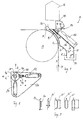
- FIG 1 shows a cleaning device 10 according to the invention when it is arranged above a wire 14 supported by a wire guide roll 12 and combined with a supporting beam 16 and a drainage hood 18.
- the cleaning device 10 comprises a nozzle 20 and two tilting cylinders 22, 24, of which the cylinder 22 is shown in Figure 1.
- the nozzle 20 is connected via a flexible water hose 24 to the water supply means in the beam 12; the supply means are not shown in the Figure.
- the nozzle 20 and the tilting cylinders 22, 24 are fastened to a mounting plate 26 which is fastened to the upper wall 18' of the drainage hood 18.
- the lower part 30 of the nozzle 20 is arranged in the opening 28 located in the mounting plate 26, the lower part being that part where the actual nozzle orifice is located, as shown in more detail in Figure 4.
- the drainage hood 18 At the upper part of the drainage hood 18 it is confined by the upper wall 18' and at its lower part it is confined by the lower wall 18", which, however, covers only a part of the lower part of the hood.
- the part of the drainage hood 18 toward the roll is open, so that it allows the water jet discharged from the nozzle 20 arranged above the hood to flow freely toward the fabric 14.
- the lowest bottom part 18"' of the drainage hood is also open, so that it allows the dirty water collected in the hood to flow out from the hood 18 into the water collecting channel 32.
- a compressed air nozzle 36 is arranged in the upper part 34 of the drainage hood.
- Figure 3 shows cross-sections of the compressed air nozzle 36 and the drainage hood 18, at the locations A to E shown in Figure 1.
- the Figure 3 shows that the hood converges both in the width and the height directions, from the bottom to the top.
- Figure 2 shows the mounting plate 26 of Figure 1 and the nozzle 20 and cylinders 22, 24 arranged in the plate.
- the cylinders are connected via the bearing 38 to the upper part 40 of the nozzle 20, as is best seen in Figure 1.
- the tilting cylinder 22 turns the nozzle 20 in the travelling direction of the fabric, or in the direction shown by the arrow a in Figure 2.
- the tilting cylinder 24 turns the nozzle 20 in the cross-direction of the fabric 14, or in the direction of the arrow b shown in Figure 2.
- FIG 4 shows in more detail the fastening of the nozzle 20 to the tilting cylinder 22 and to the mounting plate 26.
- the upper part 40 of the nozzle is connected via a bearing joint to the tilting cylinder 22.
- the bearing joint comprises a bearing housing 42 connected to the tilting cylinder via a rotating joint 44, and a ball surface bearing 46 arranged in the upper part 40 of the nozzle 20.
- the other tilting cylinder 24 (which is seen in Figure 2) is connected in a corresponding way to the bearing housing 42. Due to the ball surface bearing the nozzle can be turned around the turning point in the lower part of the nozzle into different positions, whereby the nozzle can provide a water jet which is directed at desired angles toward the fabric or wire.
- the lower part 30 of the nozzle is in a corresponding way connected via a ball surface bearing 48 with the bearing housing 50 arranged in the mounting plate 26, whereby the nozzle can be easily turned into different angles.
- the nozzle is advantageously turned about 15 degrees, as shown in Figure 4.
- Figures 5 and 6 show a cleaning device according to the invention in its different extreme positions regarding the movement of the tilting cylinder 22.
- the tilting cylinder 22 has pushed the bearing housing 42 to the left extreme position.
- the ball surface bearing 46 has turned the nozzle 20 so that it directs the water jet to the right, as seen in Figure 5.
- the tilting cylinder 22 has pulled the bearing housing 42 to the right-hand extreme position.
- the ball surface bearing 46 has turned the nozzle 20 so that it directs the water jet to the left, as seen in Figure 6.
- the nozzle turns around the turning point formed by the bearing housing 50 and the ball surface bearing 48 at the opening 28 in the mounting plate 26. In a corresponding way the nozzle can be turned with the second tilting cylinder 24 in the cross-wise direction of the fabric.
- the actual nozzle part of the nozzle i.e. the lower part of the nozzle, can be removed from the nozzle by the joint 54, 56, as seen in Figure 4, for instance for a replacement of the nozzle.
Landscapes
- Paper (AREA)
- Cleaning By Liquid Or Steam (AREA)
- Nozzles (AREA)
- Spray Control Apparatus (AREA)
- Body Washing Hand Wipes And Brushes (AREA)
Applications Claiming Priority (2)
| Application Number | Priority Date | Filing Date | Title |
|---|---|---|---|
| US09/393,293 US6360758B1 (en) | 1999-09-10 | 1999-09-10 | Cleaning device in paper machines, board machines or other similar machines for cleaning a fabric, such as wire or felt |
| US393293 | 1999-09-10 |
Publications (3)
| Publication Number | Publication Date |
|---|---|
| EP1085121A2 true EP1085121A2 (de) | 2001-03-21 |
| EP1085121A3 EP1085121A3 (de) | 2001-07-25 |
| EP1085121B1 EP1085121B1 (de) | 2004-07-21 |
Family
ID=23554109
Family Applications (1)
| Application Number | Title | Priority Date | Filing Date |
|---|---|---|---|
| EP00660152A Expired - Lifetime EP1085121B1 (de) | 1999-09-10 | 2000-09-08 | Vorrichtung zur Reinigung von Papiermaschinengewebe |
Country Status (6)
| Country | Link |
|---|---|
| US (1) | US6360758B1 (de) |
| EP (1) | EP1085121B1 (de) |
| JP (1) | JP3716168B2 (de) |
| AT (1) | ATE271626T1 (de) |
| CA (1) | CA2317263C (de) |
| DE (2) | DE60012280T2 (de) |
Cited By (3)
| Publication number | Priority date | Publication date | Assignee | Title |
|---|---|---|---|---|
| WO2011077263A2 (de) | 2009-12-21 | 2011-06-30 | Paprima Industries Inc. | Reinigungsvorrichtung |
| US9044782B2 (en) | 2010-07-12 | 2015-06-02 | Paprima Industries Inc. | Drain apparatus for a dry strainer cleaning head |
| CN113317662A (zh) * | 2021-06-18 | 2021-08-31 | 读布科技(杭州)有限公司 | 一种用于纺织印染的展示装置 |
Families Citing this family (10)
| Publication number | Priority date | Publication date | Assignee | Title |
|---|---|---|---|---|
| US6530658B1 (en) * | 2000-05-30 | 2003-03-11 | Hewlett-Packard Company | Dispensing applicator and method of use |
| DE10045694A1 (de) * | 2000-09-15 | 2002-04-04 | Infineon Technologies Ag | Halbleiterspeicherzelle mit Grabenkondensator und Auswahltransistor und Verfahren zu ihrer Herstellung |
| JP4532954B2 (ja) * | 2004-03-25 | 2010-08-25 | 淀設計工業株式会社 | 印字装置 |
| US7077260B2 (en) * | 2004-06-29 | 2006-07-18 | Gerald Michael Saballus | Device for cleaning corrugator belts |
| US20090266388A1 (en) * | 2008-04-28 | 2009-10-29 | Accessoires Pour Pates Et Papiers Ekip Ltee | Flexible showering device for a pulp and paper making machine |
| DE102015015949A1 (de) | 2015-12-08 | 2017-06-08 | Messer Austria Gmbh | Verfahren und Vorrichtung zum Behandeln eines Pressfilzes |
| EP3260802B1 (de) * | 2016-06-23 | 2019-10-09 | Valmet Technologies Oy | Düse für eine vorrichtung zur berührungslosen behandlung einer laufenden faserstoffbahn |
| CN110396851B (zh) * | 2019-07-18 | 2024-09-13 | 山鹰国际控股股份公司 | 一种纸页剥离装置 |
| EP4103031B1 (de) * | 2020-02-13 | 2025-05-07 | Kadant Nordic AB | Reinigungskopf mit gerichteter düsenanordnung und geformtem aussenluftmesser für traversierende duschsysteme |
| GB2643710A (en) * | 2024-08-28 | 2026-03-04 | Industrial Packaging Solutions Ltd | Corrugator belt cleaning assembly, system comprising the same, and method of use of the cleaning assembly |
Family Cites Families (17)
| Publication number | Priority date | Publication date | Assignee | Title |
|---|---|---|---|---|
| GB312370A (en) * | 1928-05-25 | 1930-07-31 | Victor Antoine | Apparatus for cleaning and washing the wire cloth of paper making and like machines |
| GB1484681A (en) * | 1974-01-09 | 1977-09-01 | Jwi Ltd | Guide shower for a paper making machine |
| US4073376A (en) * | 1975-04-30 | 1978-02-14 | Krooss Robert J | Conveyor cleaning mechanism |
| SU935404A1 (ru) * | 1980-10-16 | 1982-06-15 | Всесоюзный Проектный И Научно-Исследовательский Институт Промышленного Транспорта "Промтрансниипроект" Госстроя Ссср | Устройство дл очистки ленты конвейера |
| SU988702A1 (ru) * | 1981-08-10 | 1983-01-15 | Московский Ордена Трудового Красного Знамени Геологоразведочный Институт Им.С.Орджоникидзе | Устройство дл очистки ленты конвейера |
| SU1207932A1 (ru) * | 1984-07-27 | 1986-01-30 | Предприятие П/Я Г-4311 | Устройство дл очистки ленты конвейера |
| JPS61130387U (de) * | 1985-01-29 | 1986-08-15 | ||
| FR2600918B1 (fr) * | 1986-07-04 | 1990-11-16 | Adam Michel | Appareil et procede pour laver le plateau de sechage d'un sechoir-tunnel |
| SU1705205A1 (ru) * | 1986-11-26 | 1992-01-15 | Предприятие П/Я В-2262 | Устройство дл очистки ленты конвейера |
| JPS63235590A (ja) * | 1987-03-21 | 1988-09-30 | 中村 徹 | 抄紙機用ワイヤ,フエルト,カンバス等の洗浄方法および洗浄用シヤワ−ノズル |
| DE9208909U1 (de) | 1992-07-03 | 1992-09-24 | J.M. Voith Gmbh, 7920 Heidenheim | Vorrichtung zum Reinigen einer umlaufenden Gewebebahn in einer Papiermaschine |
| ATE209271T1 (de) * | 1995-02-24 | 2001-12-15 | Voith Paper Patent Gmbh | Reinigungsvorrichtung |
| EP0731211B1 (de) * | 1995-02-24 | 2002-06-05 | Voith Paper Patent GmbH | Strahleinrichtung |
| US5706932A (en) * | 1996-03-27 | 1998-01-13 | White; Robert G. | Apparatus and method of cleaning conveyor belts |
| NL1003070C2 (nl) | 1996-05-09 | 1997-11-18 | Robo Paper Engineering B V | Reinigingsinrichting voor het reinigen van een ontwateringszeef in een nat- of droogpartij of een natvilt in een perspartij van een papier- vervaardigingsmachine. |
| DE19627973A1 (de) * | 1996-07-11 | 1998-01-15 | Voith Sulzer Papiermasch Gmbh | Reinigungsvorrichtung |
| DE19702196C5 (de) * | 1997-01-23 | 2010-04-22 | Voith Patent Gmbh | Vorrichtung zum Reinigen eines Transportbandes |
-
1999
- 1999-09-10 US US09/393,293 patent/US6360758B1/en not_active Expired - Fee Related
-
2000
- 2000-08-23 JP JP2000252756A patent/JP3716168B2/ja not_active Expired - Fee Related
- 2000-08-30 CA CA002317263A patent/CA2317263C/en not_active Expired - Fee Related
- 2000-09-08 DE DE60012280T patent/DE60012280T2/de not_active Expired - Fee Related
- 2000-09-08 EP EP00660152A patent/EP1085121B1/de not_active Expired - Lifetime
- 2000-09-08 DE DE1085121T patent/DE1085121T1/de active Pending
- 2000-09-08 AT AT00660152T patent/ATE271626T1/de not_active IP Right Cessation
Cited By (9)
| Publication number | Priority date | Publication date | Assignee | Title |
|---|---|---|---|---|
| WO2011077263A2 (de) | 2009-12-21 | 2011-06-30 | Paprima Industries Inc. | Reinigungsvorrichtung |
| WO2011077263A3 (de) * | 2009-12-21 | 2011-09-01 | Paprima Industries Inc. | Reinigungsvorrichtung |
| CN102666980A (zh) * | 2009-12-21 | 2012-09-12 | 帕普里马工业有限公司 | 清洁装置 |
| EP2516735A4 (de) * | 2009-12-21 | 2014-06-18 | Paprima Ind Inc | Reinigungsvorrichtung |
| CN102666980B (zh) * | 2009-12-21 | 2015-11-25 | 帕普里马工业有限公司 | 清洁装置 |
| US9044782B2 (en) | 2010-07-12 | 2015-06-02 | Paprima Industries Inc. | Drain apparatus for a dry strainer cleaning head |
| US9732471B2 (en) | 2010-07-12 | 2017-08-15 | Paprima Industries Inc. | Drain apparatus for a dry strainer cleaning head |
| CN113317662A (zh) * | 2021-06-18 | 2021-08-31 | 读布科技(杭州)有限公司 | 一种用于纺织印染的展示装置 |
| CN113317662B (zh) * | 2021-06-18 | 2022-06-10 | 读布科技(杭州)有限公司 | 一种用于纺织印染的展示装置 |
Also Published As
| Publication number | Publication date |
|---|---|
| EP1085121B1 (de) | 2004-07-21 |
| DE1085121T1 (de) | 2001-09-06 |
| DE60012280T2 (de) | 2005-07-21 |
| JP2001115383A (ja) | 2001-04-24 |
| JP3716168B2 (ja) | 2005-11-16 |
| ATE271626T1 (de) | 2004-08-15 |
| EP1085121A3 (de) | 2001-07-25 |
| CA2317263C (en) | 2005-06-21 |
| CA2317263A1 (en) | 2001-03-10 |
| DE60012280D1 (de) | 2004-08-26 |
| US6360758B1 (en) | 2002-03-26 |
Similar Documents
| Publication | Publication Date | Title |
|---|---|---|
| US6360758B1 (en) | Cleaning device in paper machines, board machines or other similar machines for cleaning a fabric, such as wire or felt | |
| FI111652B (fi) | Puhdistuslaite | |
| US6364959B1 (en) | Process for cleaning a transport belt | |
| US5879515A (en) | Jet device | |
| PL173855B1 (pl) | Urządzenie do oczyszczania przedmiotów w ruchu | |
| US6050392A (en) | Cleaning device and process | |
| JPH06264390A (ja) | ロールの表面を洗浄する方法及びロールの表面を洗浄する装置 | |
| US6135267A (en) | Device for cleaning a transport belt | |
| CA1040237A (en) | Dust removing apparatus and method | |
| US6136148A (en) | Method for cleaning fabrics of a paper machine | |
| US5660688A (en) | Method and device for washing a wire of a paper or board machine | |
| US4698134A (en) | Method for cleaning papermaking fabrics | |
| EP1736597B1 (de) | Trockenpartie einer Papiermaschine, Anordnung und Methode zur Verminderung der Staubausbreitung darin | |
| US6468397B1 (en) | Scarfing shower for fabric cleaning in a wet papermaking process | |
| NL1003070C2 (nl) | Reinigingsinrichting voor het reinigen van een ontwateringszeef in een nat- of droogpartij of een natvilt in een perspartij van een papier- vervaardigingsmachine. | |
| EP4103031B1 (de) | Reinigungskopf mit gerichteter düsenanordnung und geformtem aussenluftmesser für traversierende duschsysteme | |
| JPH10505391A (ja) | 抄紙機または板紙抄紙機における乾燥ワイヤの洗浄方法および装置 | |
| US6153056A (en) | Device and method for draining a paper machine felt | |
| FI74747C (fi) | Anordning foer tvaettning av mattor. | |
| US20040011492A1 (en) | Application device | |
| FI90363C (fi) | Menetelmä ja laite paperikoneessa pesusumun poistamiseksi | |
| FI115312B (fi) | Puhdistuslaitteisto paperin tai kartongin viimeistelylaitetta varten | |
| US7678234B2 (en) | Dewatering arrangement on the press section of a web-forming machine | |
| US20040050519A1 (en) | Method and a device for removing water from the surface of a roller jacket | |
| CA2163538A1 (en) | Method and apparatus for use in the press or dryer section of a paper machine or similar equipment |
Legal Events
| Date | Code | Title | Description |
|---|---|---|---|
| PUAI | Public reference made under article 153(3) epc to a published international application that has entered the european phase |
Free format text: ORIGINAL CODE: 0009012 |
|
| AK | Designated contracting states |
Kind code of ref document: A2 Designated state(s): AT BE CH CY DE DK ES FI FR GB GR IE IT LI LU MC NL PT SE |
|
| AX | Request for extension of the european patent |
Free format text: AL;LT;LV;MK;RO;SI |
|
| PUAL | Search report despatched |
Free format text: ORIGINAL CODE: 0009013 |
|
| AK | Designated contracting states |
Kind code of ref document: A3 Designated state(s): AT BE CH CY DE DK ES FI FR GB GR IE IT LI LU MC NL PT SE |
|
| AX | Request for extension of the european patent |
Free format text: AL;LT;LV;MK;RO;SI |
|
| DET | De: translation of patent claims | ||
| RAP1 | Party data changed (applicant data changed or rights of an application transferred) |
Owner name: METSO PAPER, INC. |
|
| 17P | Request for examination filed |
Effective date: 20011122 |
|
| AKX | Designation fees paid |
Free format text: AT BE CH CY DE DK ES FI FR GB GR IE IT LI LU MC NL PT SE |
|
| 17Q | First examination report despatched |
Effective date: 20030818 |
|
| GRAP | Despatch of communication of intention to grant a patent |
Free format text: ORIGINAL CODE: EPIDOSNIGR1 |
|
| GRAS | Grant fee paid |
Free format text: ORIGINAL CODE: EPIDOSNIGR3 |
|
| GRAA | (expected) grant |
Free format text: ORIGINAL CODE: 0009210 |
|
| AK | Designated contracting states |
Kind code of ref document: B1 Designated state(s): AT BE CH CY DE DK ES FI FR GB GR IE IT LI LU MC NL PT SE |
|
| PG25 | Lapsed in a contracting state [announced via postgrant information from national office to epo] |
Ref country code: IT Free format text: LAPSE BECAUSE OF FAILURE TO SUBMIT A TRANSLATION OF THE DESCRIPTION OR TO PAY THE FEE WITHIN THE PRESCRIBED TIME-LIMIT;WARNING: LAPSES OF ITALIAN PATENTS WITH EFFECTIVE DATE BEFORE 2007 MAY HAVE OCCURRED AT ANY TIME BEFORE 2007. THE CORRECT EFFECTIVE DATE MAY BE DIFFERENT FROM THE ONE RECORDED. Effective date: 20040721 Ref country code: CY Free format text: LAPSE BECAUSE OF FAILURE TO SUBMIT A TRANSLATION OF THE DESCRIPTION OR TO PAY THE FEE WITHIN THE PRESCRIBED TIME-LIMIT Effective date: 20040721 Ref country code: CH Free format text: LAPSE BECAUSE OF FAILURE TO SUBMIT A TRANSLATION OF THE DESCRIPTION OR TO PAY THE FEE WITHIN THE PRESCRIBED TIME-LIMIT Effective date: 20040721 Ref country code: FR Free format text: LAPSE BECAUSE OF FAILURE TO SUBMIT A TRANSLATION OF THE DESCRIPTION OR TO PAY THE FEE WITHIN THE PRESCRIBED TIME-LIMIT Effective date: 20040721 Ref country code: BE Free format text: LAPSE BECAUSE OF FAILURE TO SUBMIT A TRANSLATION OF THE DESCRIPTION OR TO PAY THE FEE WITHIN THE PRESCRIBED TIME-LIMIT Effective date: 20040721 Ref country code: LI Free format text: LAPSE BECAUSE OF FAILURE TO SUBMIT A TRANSLATION OF THE DESCRIPTION OR TO PAY THE FEE WITHIN THE PRESCRIBED TIME-LIMIT Effective date: 20040721 |
|
| REG | Reference to a national code |
Ref country code: GB Ref legal event code: FG4D |
|
| REG | Reference to a national code |
Ref country code: CH Ref legal event code: EP |
|
| REG | Reference to a national code |
Ref country code: IE Ref legal event code: FG4D |
|
| REF | Corresponds to: |
Ref document number: 60012280 Country of ref document: DE Date of ref document: 20040826 Kind code of ref document: P |
|
| PG25 | Lapsed in a contracting state [announced via postgrant information from national office to epo] |
Ref country code: IE Free format text: LAPSE BECAUSE OF NON-PAYMENT OF DUE FEES Effective date: 20040908 Ref country code: LU Free format text: LAPSE BECAUSE OF NON-PAYMENT OF DUE FEES Effective date: 20040908 |
|
| PG25 | Lapsed in a contracting state [announced via postgrant information from national office to epo] |
Ref country code: MC Free format text: LAPSE BECAUSE OF NON-PAYMENT OF DUE FEES Effective date: 20040930 |
|
| PG25 | Lapsed in a contracting state [announced via postgrant information from national office to epo] |
Ref country code: DK Free format text: LAPSE BECAUSE OF FAILURE TO SUBMIT A TRANSLATION OF THE DESCRIPTION OR TO PAY THE FEE WITHIN THE PRESCRIBED TIME-LIMIT Effective date: 20041021 Ref country code: GR Free format text: LAPSE BECAUSE OF FAILURE TO SUBMIT A TRANSLATION OF THE DESCRIPTION OR TO PAY THE FEE WITHIN THE PRESCRIBED TIME-LIMIT Effective date: 20041021 Ref country code: GB Free format text: LAPSE BECAUSE OF NON-PAYMENT OF DUE FEES Effective date: 20041021 |
|
| PG25 | Lapsed in a contracting state [announced via postgrant information from national office to epo] |
Ref country code: ES Free format text: LAPSE BECAUSE OF FAILURE TO SUBMIT A TRANSLATION OF THE DESCRIPTION OR TO PAY THE FEE WITHIN THE PRESCRIBED TIME-LIMIT Effective date: 20041101 |
|
| REG | Reference to a national code |
Ref country code: SE Ref legal event code: TRGR |
|
| REG | Reference to a national code |
Ref country code: CH Ref legal event code: PL |
|
| PLBE | No opposition filed within time limit |
Free format text: ORIGINAL CODE: 0009261 |
|
| STAA | Information on the status of an ep patent application or granted ep patent |
Free format text: STATUS: NO OPPOSITION FILED WITHIN TIME LIMIT |
|
| GBPC | Gb: european patent ceased through non-payment of renewal fee |
Effective date: 20041021 |
|
| REG | Reference to a national code |
Ref country code: IE Ref legal event code: MM4A |
|
| 26N | No opposition filed |
Effective date: 20050422 |
|
| EN | Fr: translation not filed | ||
| PG25 | Lapsed in a contracting state [announced via postgrant information from national office to epo] |
Ref country code: PT Free format text: LAPSE BECAUSE OF NON-PAYMENT OF DUE FEES Effective date: 20041221 |
|
| PGFP | Annual fee paid to national office [announced via postgrant information from national office to epo] |
Ref country code: AT Payment date: 20080915 Year of fee payment: 9 Ref country code: FI Payment date: 20080915 Year of fee payment: 9 Ref country code: NL Payment date: 20080915 Year of fee payment: 9 |
|
| PGFP | Annual fee paid to national office [announced via postgrant information from national office to epo] |
Ref country code: DE Payment date: 20080919 Year of fee payment: 9 |
|
| PGFP | Annual fee paid to national office [announced via postgrant information from national office to epo] |
Ref country code: SE Payment date: 20080912 Year of fee payment: 9 |
|
| REG | Reference to a national code |
Ref country code: NL Ref legal event code: V1 Effective date: 20100401 |
|
| PG25 | Lapsed in a contracting state [announced via postgrant information from national office to epo] |
Ref country code: FI Free format text: LAPSE BECAUSE OF NON-PAYMENT OF DUE FEES Effective date: 20090908 |
|
| EUG | Se: european patent has lapsed | ||
| PG25 | Lapsed in a contracting state [announced via postgrant information from national office to epo] |
Ref country code: AT Free format text: LAPSE BECAUSE OF NON-PAYMENT OF DUE FEES Effective date: 20090908 |
|
| PG25 | Lapsed in a contracting state [announced via postgrant information from national office to epo] |
Ref country code: NL Free format text: LAPSE BECAUSE OF NON-PAYMENT OF DUE FEES Effective date: 20100401 Ref country code: DE Free format text: LAPSE BECAUSE OF NON-PAYMENT OF DUE FEES Effective date: 20100401 |
|
| PG25 | Lapsed in a contracting state [announced via postgrant information from national office to epo] |
Ref country code: SE Free format text: LAPSE BECAUSE OF NON-PAYMENT OF DUE FEES Effective date: 20090909 |