EP1085129B1 - Einrichtung zum Schmieren der Schienenbefestigungsvorrichtungen eines Gleises - Google Patents
Einrichtung zum Schmieren der Schienenbefestigungsvorrichtungen eines Gleises Download PDFInfo
- Publication number
- EP1085129B1 EP1085129B1 EP00810811A EP00810811A EP1085129B1 EP 1085129 B1 EP1085129 B1 EP 1085129B1 EP 00810811 A EP00810811 A EP 00810811A EP 00810811 A EP00810811 A EP 00810811A EP 1085129 B1 EP1085129 B1 EP 1085129B1
- Authority
- EP
- European Patent Office
- Prior art keywords
- rail
- fixing means
- lubricating fluid
- bearing members
- consist
- Prior art date
- Legal status (The legal status is an assumption and is not a legal conclusion. Google has not performed a legal analysis and makes no representation as to the accuracy of the status listed.)
- Expired - Lifetime
Links
- 238000005461 lubrication Methods 0.000 title claims abstract description 11
- 239000012530 fluid Substances 0.000 claims abstract description 17
- 230000001050 lubricating effect Effects 0.000 claims abstract description 15
- 238000006073 displacement reaction Methods 0.000 claims abstract description 4
- 230000000295 complement effect Effects 0.000 claims description 3
- 230000003137 locomotive effect Effects 0.000 claims description 2
- 230000000284 resting effect Effects 0.000 claims 1
- 230000000694 effects Effects 0.000 description 3
- 230000003647 oxidation Effects 0.000 description 2
- 238000007254 oxidation reaction Methods 0.000 description 2
- 238000004873 anchoring Methods 0.000 description 1
- 230000007797 corrosion Effects 0.000 description 1
- 238000005260 corrosion Methods 0.000 description 1
- 238000005516 engineering process Methods 0.000 description 1
- 239000011810 insulating material Substances 0.000 description 1
- 239000002184 metal Substances 0.000 description 1
- 230000000737 periodic effect Effects 0.000 description 1
- 238000005086 pumping Methods 0.000 description 1
- 238000009877 rendering Methods 0.000 description 1
- 238000003466 welding Methods 0.000 description 1
Images

Classifications
-
- E—FIXED CONSTRUCTIONS
- E01—CONSTRUCTION OF ROADS, RAILWAYS, OR BRIDGES
- E01B—PERMANENT WAY; PERMANENT-WAY TOOLS; MACHINES FOR MAKING RAILWAYS OF ALL KINDS
- E01B31/00—Working rails, sleepers, baseplates, or the like, in or on the line; Machines, tools, or auxiliary devices specially designed therefor
Definitions
- the present invention relates to the field of technology comprising means which are used for the lubrication of metal members for the purpose of protecting them against corrosion and prolonging their serviceability.
- the device according to the invention concerns the specific sector of lubrication of the plurality of elements provided with a projecting part which are arranged at regular intervals along a linear member for which they serve as anchoring, connection and/or jointing means.
- a typical case in which the abovementioned device can be advantageously used is that of lubrication of the fixing means, such as bolts with or without ring nuts, washers or other small parts, which serve for fixing railway tracks on their support sleepers.
- such bolts are arranged, with their heads projecting upwards, at regular intervals along the entire length of the tracks and are fixed on both bearing sides of each of the two parallel elements (the rails) which form a track. It is periodically necessary to carry out lubrication of the parts of said bolts, such as the head and the threaded shaft, to avoid oxidation reducing the reliability of their fixing with the passing of time and rendering their removal by means of unscrewing problematic and extremely difficult.
- the abovementioned lubrication is performed manually by an operative who, while walking along a track, uses a brush to take a lubricating fluid from a bucket containing it and apply it to said bolts.
- the inventor of the present invention has designed a device which, mounted on a rail, can run along the latter, pushed by an operative or by other means, and automatically effect the lubrication of all the fixing bolts that it encounters as it travels along.
- Documents DE-A-37 09 390 and FR-A-2051740 show already machines for lubrication of the fixing bolts of the rails, with a reservoir for the lubricating fluid and with bearing wheels for supporting the machine on the rails.
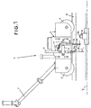
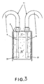
- the device 1 comprises primarily a body 2, also constituting its bearing structure, which contains lubricating fluid 18 in a suitable tank 17 in its interior (see Figure 3).
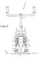
- Said body is supported by bearing members consisting of two small wheels 3, 4 made of insulating material, although they can also consist of one or more sliding blocks (not shown).
- Said bearing members have a groove 14 which, in the case shown, extends over the entire external contact surface of the small wheels 3, 4 and has a shape which is complementary to that of the rail 8, as can be seen in Figure 2.
- the ends of two tubes 5, 6, which are preferably each provided with a unidirectional valve 21 which prevents the fluid flowing back from the tubes 5, 6 to the tank 17, extend down into said tank 17 containing the lubricating fluid 18.
- Said tubes 5, 6 are bent in a U shape and their other end is terminated by an ejection nozzle 5u, 6u which is directed downwards, that is to say towards the fixing means 8 to be lubricated, with an appropriate inclination ⁇ in relation to the vertical, the purposes of which will be defined in the course of the description.
- Each of said two tubes 5, 6 forms part, together with said tank 17, of a hydraulic system 11 provided with a mechanical pump 12 of the positive-displacement type, the pressure piston 19 of which is connected to a striker member, a simple mechanical arm 13 in this case, which is articulated on the body 2 and is directed downwards, that is to say towards the bearing plane of the rail 9.
- Said arm 13 is shaped and dimensioned in such a manner that, during the translation of the device 1 along a rail 9, its free end 131 strikes against those parts 8s of the fixing means 8 of the rail 9 which project upwards in relation to said bearing plane ⁇ , rotating (see arrow A) on account of the impact so as to overcome the obstacle without causing the translation movement of the device 1 to stop or to decelerate appreciably.
- a counter-spring 15 fixed to the other end of the arm 13 then returns it to its starting position by making it counter-rotate (see arrow B).
- the pressure piston 19 of the abovementioned pump 12 takes into a chamber 20 a predetermined quantity of lubricating fluid 18 from the tank 17 by means of the respective tube 5 and then, on account of the counter-rotation B, conveys it to the associated nozzle 5u in which the tube 5 terminates towards the outside.
- the hydraulic systems can be dimensioned in such a manner that the lubricating fluid 18, leaving the nozzles 5u, 6u at a predetermined pressure, is atomized to the appropriate degree by the latter, increasing its capacity to penetrate even the narrow gaps of the fixing means which is usually a captive bolt 8 as represented in the drawings.
- the pumping and ejection operation takes place with a certain advance in relation to the moment at which the ejection nozzle 5u, 6u passes through the vertical of the fixing means 8.
- the inventor has consequently made provision for the nozzles 5u, 6u, or the terminal length of the tubes 5, 6 connected thereto, to be orientated so as to achieve a predetermined inclination ⁇ in relation to the vertical, as can be seen in Fig. 1, which makes it possible to direct the jet towards the point where the fixing means 8 to be lubricated is situated at the moment when ejection of the fluid takes place.
- the device 1 In order to operate, the device 1 according to the invention must, as mentioned, be made to move on its bearing members 3, 4 along the rail 9, the fixing means 8 of which are to be lubricated. To this end, the inventor has made provision to equip the device 1 with handlebars 7 which can be held and manoeuvred with ease by an operative following the course of the rail 9 on foot.
- the device can be made to move by a railway carriage or by a locomotive connected to it by an appropriate frame (not shown because it is easy to imagine and to put into effect), or can generate its own motion by means of a DC electric motor powered by batteries, which is secured with these on the body 2 of the device 1. (This case is not shown either for reasons similar to those in the preceding case.)
- the device according to the invention affords an effective means of easily carrying out the periodic lubrication of sections of railway line, reducing the effort and the danger involved for the operatives performing the work, appreciably increasing the functionality and the reliability of the result, and moreover allowing a considerable saving on the quantity of lubricating fluid used.
Landscapes
- Engineering & Computer Science (AREA)
- Mechanical Engineering (AREA)
- Architecture (AREA)
- Civil Engineering (AREA)
- Structural Engineering (AREA)
- Machines For Laying And Maintaining Railways (AREA)
- Lubricants (AREA)
Claims (7)
- Vorrichtung (1) zum Schmieren der Befestigungsmittel (8) der Schienen (9) eines Gleisstrangs (10), wobei die Befestigungsmittel (8) auf gegenüberliegenden Seite jeder Schiene (9) angeordnet sind und einen in Bezug auf die Befestigungsebene (γ) nach oben vorstehenden Teil (8s) besitzen, mit:gekennzeichnet durcheinem Körper (2), der in seinem Innenraum Schmierfluid enthält; undeinem oder mehreren Lagerelementen (3, 4), die den Körper (2) unterstützen und sich in einen Kontakt mit der Schiene (9) bewegen können, wenn sie durch eine Antriebskraft (7) angeschoben werden;zwei Rohre (5, 6), die sich mit einem Ende nach unten in das in dem Körper (2) enthaltenen Schmierfluid erstrecken und am anderen Ende in einer Ausspritzdüse (5u, 6u) enden, die in Bezug auf die Vertikale unter einen Winkel nach unten gerichtet ist, wobei jedes der zwei Rohre (5, 6) einen Teil eines Hydrauliksystems (11) bildet, das mit einer mechanischen Pumpe (12) des Typs mit positiver Verdrängung versehen ist, die das Schmierfluid (18) zu den Ausspritzdüsen (5u, 6u) fördert und durch ein Schlagelement (13), das an dem Körper (2) angelenkt und zu der Lagerebene (γ) der Schiene (9) gerichtet ist, betätigt wird, wenn dieses Schlagelement (13) gegen den vorstehenden Teil (8s) der Befestigungsmittel (8) schiebt, wenn die Vorrichtung (1) längs der Schiene (9) translatorisch bewegt wird.
- Vorrichtung nach Anspruch 1, bei der die Lagerelemente aus wenigstens zwei kleinen Rädern (3, 4) bestehen, auf deren gesamter äußerster Oberfläche eine Nut (14) ausgebildet ist, deren Form zu jener der Schiene (9), auf der die kleinen Räder (3, 4) unterstützt werden, komplementär ist.
- Vorrichtung nach Anspruch 1, bei der die Lagerelemente aus einem oder mehreren Blöcken bestehen, die mittels Nuten, die sich über die gesamte Kontaktfläche erstrecken und eine Form haben, die zu jener der Schiene (9) komplementär ist, auf dieser Schiene (9) liegen.
- Vorrichtung nach einem der vorhergehenden Ansprüche, bei der die Antriebsmittel, die die Lagerelemente (3, 4) durch Schieben bewegen können, aus manuell betätigbaren Handhebeln (7) bestehen, die mit der Vorrichtung (1) verbunden sind.
- Vorrichtung nach einem der Ansprüche 1 bis 3, bei der die Antriebsmittel, die die Lagerelemente durch Schieben bewegen können, aus einem Rahmen bestehen, der die Vorrichtung mit einem Schlitten oder mit einer Eisenbahnlokomotive verbinden kann.
- Vorrichtung nach Anspruch 2, bei der die Antriebsmittel aus einem Elektromotor bestehen, der einteilig an dem Körper (2) angebracht ist und durch an dem Körper (2) befestigte Batterien mit Leistung versorgt wird.
- Vorrichtung nach einem der vorhergehenden Ansprüche, bei der das Schlagelement, das nach unten vorsteht und die mechanische Pumpe (12) betätigt, ein mit ihrem Druckkolben (19) verbundener Arm ist und am Körper (2) der Vorrichtung (1) angelenkt ist, wobei der Arm so geformt und bemessen ist, dass während der translatorischen Bewegung der Vorrichtung (1) das freie Ende (13) des Arms gegen den vorstehenden Teil (8s) der Befestigungsmittel (8) schlägt, die ihrerseits so beschaffen sind, dass sie durch diesen Teil gedreht werden, woraufhin der Arm, nachdem er sich an dem Teil vorbeibewegt hat, in seine Ausgangsposition zurückkehrt, indem er sich kraft der Wirkung einer Gegenfeder (15) in entgegengesetzter Richtung dreht, wobei die Drehung und die Gegendrehung das Ansaugen des in dem Körper (2) enthaltenen Schmierfluids bzw. dessen Ausstoß durch die Düsen (5u, 6u) herbeiführen.
Applications Claiming Priority (2)
| Application Number | Priority Date | Filing Date | Title |
|---|---|---|---|
| CH168099 | 1999-09-14 | ||
| CH168099 | 1999-09-14 |
Publications (3)
| Publication Number | Publication Date |
|---|---|
| EP1085129A2 EP1085129A2 (de) | 2001-03-21 |
| EP1085129A3 EP1085129A3 (de) | 2001-07-18 |
| EP1085129B1 true EP1085129B1 (de) | 2005-01-26 |
Family
ID=4216088
Family Applications (1)
| Application Number | Title | Priority Date | Filing Date |
|---|---|---|---|
| EP00810811A Expired - Lifetime EP1085129B1 (de) | 1999-09-14 | 2000-09-08 | Einrichtung zum Schmieren der Schienenbefestigungsvorrichtungen eines Gleises |
Country Status (3)
| Country | Link |
|---|---|
| EP (1) | EP1085129B1 (de) |
| AT (1) | ATE287991T1 (de) |
| DE (1) | DE60017656T2 (de) |
Cited By (1)
| Publication number | Priority date | Publication date | Assignee | Title |
|---|---|---|---|---|
| CN110616600A (zh) * | 2019-06-24 | 2019-12-27 | 中国路桥工程有限责任公司 | 铁路工程风险管理系统 |
Families Citing this family (2)
| Publication number | Priority date | Publication date | Assignee | Title |
|---|---|---|---|---|
| CN103866660B (zh) * | 2012-12-13 | 2016-03-23 | 昆明中铁大型养路机械集团有限公司 | 一种小型高速无砟轨道的绳锯切割设备 |
| CN103966931B (zh) * | 2014-04-23 | 2016-01-27 | 徐州徐工铁路装备有限公司 | 一种高速铁路无砟轨道砂浆层索锯切割机 |
Family Cites Families (4)
| Publication number | Priority date | Publication date | Assignee | Title |
|---|---|---|---|---|
| FR1426325A (fr) * | 1964-12-15 | 1966-01-28 | Montmorency Atel | Machine pour le vissage ou le dévissage de tirefonds ou boulons |
| AT310220B (de) * | 1968-07-15 | 1973-09-25 | Plasser Bahnbaumasch Franz | Fahrbare Vorrichtung zur Behandlung der Schienenbefestigungen eines Gleises |
| AT306774B (de) * | 1968-10-25 | 1973-04-25 | Plasser Bahnbaumasch Franz | Fahrbare Einrichtung zur Behandlung von Gleisen |
| DE3709390A1 (de) * | 1987-03-21 | 1988-09-29 | Cemafer Gleisbaumaschinen Und | Schraubmaschine fuer arbeiten an eisenbahnschienen |
-
2000
- 2000-09-08 EP EP00810811A patent/EP1085129B1/de not_active Expired - Lifetime
- 2000-09-08 DE DE60017656T patent/DE60017656T2/de not_active Expired - Lifetime
- 2000-09-08 AT AT00810811T patent/ATE287991T1/de not_active IP Right Cessation
Cited By (1)
| Publication number | Priority date | Publication date | Assignee | Title |
|---|---|---|---|---|
| CN110616600A (zh) * | 2019-06-24 | 2019-12-27 | 中国路桥工程有限责任公司 | 铁路工程风险管理系统 |
Also Published As
| Publication number | Publication date |
|---|---|
| ATE287991T1 (de) | 2005-02-15 |
| EP1085129A2 (de) | 2001-03-21 |
| DE60017656T2 (de) | 2005-12-29 |
| EP1085129A3 (de) | 2001-07-18 |
| DE60017656D1 (de) | 2005-03-03 |
Similar Documents
| Publication | Publication Date | Title |
|---|---|---|
| CN109730579B (zh) | 一种玻璃幕墙清洁装置 | |
| EP1085129A2 (de) | Einrichtung zum Schmieren der Schienenbefestigungsvorrichtungen eines Gleises | |
| ES2094598T3 (es) | Instalacion para limpiar un vehiculo de dos ruedas, especialmente una bicicleta. | |
| CN218697338U (zh) | 一种管道内壁除锈装置 | |
| WO1988008900A1 (en) | Method and device for cleaning of rails | |
| KR20240161677A (ko) | 볼트들 상에 사전 나사 결합된 일련의 너트들을 조이기 위한 조임 장치 | |
| CN120534723A (zh) | 一种煤矿井下电机车运输方法和系统 | |
| JP2005090068A (ja) | 作業車両 | |
| CN119084262A (zh) | 一种风力发电机塔筒清理装置 | |
| CN217415711U (zh) | 一种混凝土罐车冲洗装置 | |
| CN218268392U (zh) | 一种地下管廊视觉巡检机器人 | |
| CN208213847U (zh) | 一种管道机器人及其清洗装置 | |
| CN213770964U (zh) | 一种能够降低电梯摩擦力的电梯导轨 | |
| CN221133344U (zh) | 三轨罩清洁装置及铁路清洁系统 | |
| CN222970534U (zh) | 一种流体输送管道内壁清洁设备 | |
| CN220884337U (zh) | 一种洗车机用轮刷机构 | |
| CN215240049U (zh) | 一种使用寿命长的铁路轨道用除锈装置 | |
| CN214925512U (zh) | 混凝土箱梁养护用喷水装置 | |
| CN221700131U (zh) | 下降无动力自动化斜坡轨道 | |
| CN224199734U (zh) | 一种铁路轨道锈痕打磨设备 | |
| CN217015920U (zh) | 一种用于建筑施工的喷淋降尘装置 | |
| CN2430224Y (zh) | 道路护栏清洗装置 | |
| CN221958634U (zh) | 一种双轨站栓同步自动喷脂系统 | |
| CN215793791U (zh) | 一种单轨运输装置的制动组件 | |
| CN224159258U (zh) | 一种挖掘机清洗装置 |
Legal Events
| Date | Code | Title | Description |
|---|---|---|---|
| PUAI | Public reference made under article 153(3) epc to a published international application that has entered the european phase |
Free format text: ORIGINAL CODE: 0009012 |
|
| AK | Designated contracting states |
Kind code of ref document: A2 Designated state(s): AT BE CH CY DE DK ES FI FR GB GR IE IT LI LU MC NL PT SE |
|
| AX | Request for extension of the european patent |
Free format text: AL;LT;LV;MK;RO;SI |
|
| PUAL | Search report despatched |
Free format text: ORIGINAL CODE: 0009013 |
|
| AK | Designated contracting states |
Kind code of ref document: A3 Designated state(s): AT BE CH CY DE DK ES FI FR GB GR IE IT LI LU MC NL PT SE |
|
| AX | Request for extension of the european patent |
Free format text: AL;LT;LV;MK;RO;SI |
|
| 17P | Request for examination filed |
Effective date: 20010918 |
|
| AKX | Designation fees paid |
Free format text: AT BE CH CY DE DK ES FI FR GB GR IE IT LI LU MC NL PT SE |
|
| GRAP | Despatch of communication of intention to grant a patent |
Free format text: ORIGINAL CODE: EPIDOSNIGR1 |
|
| GRAS | Grant fee paid |
Free format text: ORIGINAL CODE: EPIDOSNIGR3 |
|
| GRAA | (expected) grant |
Free format text: ORIGINAL CODE: 0009210 |
|
| RAP1 | Party data changed (applicant data changed or rights of an application transferred) |
Owner name: ROSSI, PIERGIORGIO |
|
| RIN1 | Information on inventor provided before grant (corrected) |
Inventor name: ROSSI, PIERGIORGIO |
|
| AK | Designated contracting states |
Kind code of ref document: B1 Designated state(s): AT BE CH CY DE DK ES FI FR GB GR IE IT LI LU MC NL PT SE |
|
| PG25 | Lapsed in a contracting state [announced via postgrant information from national office to epo] |
Ref country code: FI Free format text: LAPSE BECAUSE OF FAILURE TO SUBMIT A TRANSLATION OF THE DESCRIPTION OR TO PAY THE FEE WITHIN THE PRESCRIBED TIME-LIMIT Effective date: 20050126 Ref country code: AT Free format text: LAPSE BECAUSE OF FAILURE TO SUBMIT A TRANSLATION OF THE DESCRIPTION OR TO PAY THE FEE WITHIN THE PRESCRIBED TIME-LIMIT Effective date: 20050126 Ref country code: NL Free format text: LAPSE BECAUSE OF FAILURE TO SUBMIT A TRANSLATION OF THE DESCRIPTION OR TO PAY THE FEE WITHIN THE PRESCRIBED TIME-LIMIT Effective date: 20050126 Ref country code: BE Free format text: LAPSE BECAUSE OF FAILURE TO SUBMIT A TRANSLATION OF THE DESCRIPTION OR TO PAY THE FEE WITHIN THE PRESCRIBED TIME-LIMIT Effective date: 20050126 |
|
| REG | Reference to a national code |
Ref country code: GB Ref legal event code: FG4D |
|
| REG | Reference to a national code |
Ref country code: CH Ref legal event code: EP |
|
| REG | Reference to a national code |
Ref country code: IE Ref legal event code: FG4D |
|
| REF | Corresponds to: |
Ref document number: 60017656 Country of ref document: DE Date of ref document: 20050303 Kind code of ref document: P |
|
| REG | Reference to a national code |
Ref country code: CH Ref legal event code: NV Representative=s name: FIAMMENGHI-FIAMMENGHI |
|
| PG25 | Lapsed in a contracting state [announced via postgrant information from national office to epo] |
Ref country code: SE Free format text: LAPSE BECAUSE OF FAILURE TO SUBMIT A TRANSLATION OF THE DESCRIPTION OR TO PAY THE FEE WITHIN THE PRESCRIBED TIME-LIMIT Effective date: 20050426 Ref country code: GR Free format text: LAPSE BECAUSE OF FAILURE TO SUBMIT A TRANSLATION OF THE DESCRIPTION OR TO PAY THE FEE WITHIN THE PRESCRIBED TIME-LIMIT Effective date: 20050426 Ref country code: DK Free format text: LAPSE BECAUSE OF FAILURE TO SUBMIT A TRANSLATION OF THE DESCRIPTION OR TO PAY THE FEE WITHIN THE PRESCRIBED TIME-LIMIT Effective date: 20050426 |
|
| PG25 | Lapsed in a contracting state [announced via postgrant information from national office to epo] |
Ref country code: ES Free format text: LAPSE BECAUSE OF FAILURE TO SUBMIT A TRANSLATION OF THE DESCRIPTION OR TO PAY THE FEE WITHIN THE PRESCRIBED TIME-LIMIT Effective date: 20050507 |
|
| NLV1 | Nl: lapsed or annulled due to failure to fulfill the requirements of art. 29p and 29m of the patents act | ||
| PG25 | Lapsed in a contracting state [announced via postgrant information from national office to epo] |
Ref country code: CY Free format text: LAPSE BECAUSE OF FAILURE TO SUBMIT A TRANSLATION OF THE DESCRIPTION OR TO PAY THE FEE WITHIN THE PRESCRIBED TIME-LIMIT Effective date: 20050908 Ref country code: GB Free format text: LAPSE BECAUSE OF NON-PAYMENT OF DUE FEES Effective date: 20050908 Ref country code: IE Free format text: LAPSE BECAUSE OF NON-PAYMENT OF DUE FEES Effective date: 20050908 |
|
| PG25 | Lapsed in a contracting state [announced via postgrant information from national office to epo] |
Ref country code: MC Free format text: LAPSE BECAUSE OF NON-PAYMENT OF DUE FEES Effective date: 20050930 Ref country code: LU Free format text: LAPSE BECAUSE OF NON-PAYMENT OF DUE FEES Effective date: 20050930 |
|
| PLBE | No opposition filed within time limit |
Free format text: ORIGINAL CODE: 0009261 |
|
| STAA | Information on the status of an ep patent application or granted ep patent |
Free format text: STATUS: NO OPPOSITION FILED WITHIN TIME LIMIT |
|
| ET | Fr: translation filed | ||
| 26N | No opposition filed |
Effective date: 20051027 |
|
| GBPC | Gb: european patent ceased through non-payment of renewal fee |
Effective date: 20050908 |
|
| REG | Reference to a national code |
Ref country code: IE Ref legal event code: MM4A |
|
| PG25 | Lapsed in a contracting state [announced via postgrant information from national office to epo] |
Ref country code: PT Free format text: LAPSE BECAUSE OF NON-PAYMENT OF DUE FEES Effective date: 20050626 |
|
| REG | Reference to a national code |
Ref country code: FR Ref legal event code: PLFP Year of fee payment: 16 |
|
| REG | Reference to a national code |
Ref country code: FR Ref legal event code: PLFP Year of fee payment: 17 |
|
| REG | Reference to a national code |
Ref country code: FR Ref legal event code: PLFP Year of fee payment: 18 |
|
| REG | Reference to a national code |
Ref country code: FR Ref legal event code: PLFP Year of fee payment: 19 |
|
| PGFP | Annual fee paid to national office [announced via postgrant information from national office to epo] |
Ref country code: FR Payment date: 20190925 Year of fee payment: 20 |
|
| PGFP | Annual fee paid to national office [announced via postgrant information from national office to epo] |
Ref country code: DE Payment date: 20190926 Year of fee payment: 20 Ref country code: CH Payment date: 20190715 Year of fee payment: 20 |
|
| PGFP | Annual fee paid to national office [announced via postgrant information from national office to epo] |
Ref country code: IT Payment date: 20190926 Year of fee payment: 20 |
|
| REG | Reference to a national code |
Ref country code: DE Ref legal event code: R071 Ref document number: 60017656 Country of ref document: DE |
|
| REG | Reference to a national code |
Ref country code: CH Ref legal event code: PL |