EP1085130A2 - Marteau de battage de pieux - Google Patents
Marteau de battage de pieux Download PDFInfo
- Publication number
- EP1085130A2 EP1085130A2 EP00307356A EP00307356A EP1085130A2 EP 1085130 A2 EP1085130 A2 EP 1085130A2 EP 00307356 A EP00307356 A EP 00307356A EP 00307356 A EP00307356 A EP 00307356A EP 1085130 A2 EP1085130 A2 EP 1085130A2
- Authority
- EP
- European Patent Office
- Prior art keywords
- weight
- anvil
- piling
- impact
- chamber
- Prior art date
- Legal status (The legal status is an assumption and is not a legal conclusion. Google has not performed a legal analysis and makes no representation as to the accuracy of the status listed.)
- Withdrawn
Links
Images



Classifications
-
- E—FIXED CONSTRUCTIONS
- E02—HYDRAULIC ENGINEERING; FOUNDATIONS; SOIL SHIFTING
- E02D—FOUNDATIONS; EXCAVATIONS; EMBANKMENTS; UNDERGROUND OR UNDERWATER STRUCTURES
- E02D7/00—Methods or apparatus for placing sheet pile bulkheads, piles, mouldpipes, or other moulds
- E02D7/02—Placing by driving
- E02D7/06—Power-driven drivers
- E02D7/10—Power-driven drivers with pressure-actuated hammer, i.e. the pressure fluid acting directly on the hammer structure
-
- E—FIXED CONSTRUCTIONS
- E02—HYDRAULIC ENGINEERING; FOUNDATIONS; SOIL SHIFTING
- E02D—FOUNDATIONS; EXCAVATIONS; EMBANKMENTS; UNDERGROUND OR UNDERWATER STRUCTURES
- E02D13/00—Accessories for placing or removing piles or bulkheads, e.g. noise attenuating chambers
- E02D13/10—Follow-blocks of pile-drivers or like devices
Definitions
- the present invention relates to piling hammers.
- Piling hammers are used for driving elongate piles into the ground, for instance to support building foundations, walls and the like.
- Typical piling hammers are powered by hydraulic or pneumatic fluid and many use impacts to generate forces to drive piles. Consequently, noise is a significant problem when these hammers are in use.
- the present invention provides a piling hammer comprising an anvil member which, in use, is placed against the pile to be driven, a weight, and reciprocating means operable to reciprocate the weight to impact repeatedly on the anvil to create piling forces, wherein the hammer further comprises chamber means within which impacts of the weight and anvil take place, the chamber means being substantially completely enclosed around the impact, whereby to contain noise created by impacts.
- the chamber has a mouth which is closed by the anvil, the weight being reciprocatable within the chamber.
- the chamber may be cylindrical, the weight forming a piston therein.
- the weight may be reciprocatable by means of pressurised fluid.
- the anvil may be movable within the mouth, relative to the chamber, under impact from the weight, the mouth remaining closed while the weight so moves.
- the reciprocating means may be operable to provide pressurised fluid to raise the weight.
- the reciprocating means is preferably operable to release pressure from the weight, thereby allowing the weight to fall.
- the hammer may further comprise at least one cushion member provided within the hammer to provide cushioning between surfaces which impact during use, whereby to reduce noise created by impacts.
- the chamber means may be formed substantially to prevent the material of the chamber means vibrating at an audible frequency after an impact.
- the anvil means preferably has a mass which is at least one eighth of the mass of the weight.
- a hammer according to this aspect of the invention may incorporate any, or any combination of features of other aspects of the invention.
- the invention provides a piling hammer comprising an anvil member which, in use, is placed against the pile to be driven, a weight, and reciprocating means operable to reciprocate the weight to impact repeatedly on the anvil to create piling forces, wherein at least one cushion member is provided within the hammer to provide cushioning between surfaces which impact during use, whereby to reduce noise created by impacts.
- a cushion member is provided between impacting surfaces of the weight and the anvil member.
- the anvil member may move within a guide housing upon impact, there being cushion members provided between the weight and the guide housing and/or between the guide housing and the anvil member, whereby the weight, the anvil member and the guide housing are cushioned when coming to rest relative to each other after an impact.
- Bearing means are preferably provided between the weight and the guide housing.
- each cushion member is resilient and may preferably be of a synthetic plastics material, such as a urethane.
- the hammer may further comprise chamber means within which impacts of the weight and anvil take place, the chamber means being substantially completely enclosed around the impact, whereby to contain noise created by impacts.
- the chamber means may be formed substantially to prevent the material of the chamber means vibrating at an audible frequency after an impact.
- the anvil means may have a mass which is at least one eighth of the mass of the weight.
- a hammer according to this aspect of the invention may incorporate any, or any combination of features of other aspects of the invention.
- a piling hammer comprising an anvil member which, in use, is placed against the pile to be driven, a weight, and reciprocating means operable to reciprocate the weight to impact repeatedly on the anvil to create piling forces, the hammer further comprising chamber means within which impacts of the weight and anvil take place, the chamber means being formed substantially to prevent the material of the chamber means vibrating at an audible frequency after an impact.
- the material of the chamber means is preferably sufficiently thick to substantially prevent vibration as aforesaid.
- the material thickness is preferably greater than is required to provide the chamber means with strength adequate to withstand forces experienced during use.
- the chamber may be substantially completely enclosed around the impact, whereby to contain noise created by impacts.
- At least one cushion member is preferably provided within the hammer to provide cushioning between surfaces which impact during use, whereby to reduce noise created by impacts.
- the anvil means preferably has a mass which is at least one eighth of the mass of the weight.
- a hammer according to this aspect of the invention may incorporate any, or any combination of features of the other aspects of the invention.
- the invention provides a piling hammer comprising an anvil member which, in use, is placed against the pile to be driven, a weight, and reciprocating means operable to reciprocate the weight to impact repeatedly on the anvil to create piling forces, wherein the anvil means has a mass which is at least one eighth of the mass of the weight.
- the anvil member has a mass of substantially 450kg or more.
- the weight may have a mass of 3,000kg or more.
- the hammer preferably further comprises chamber means within which impacts of the weight and anvil take place, the chamber means being substantially completely enclosed around the impact, whereby to contain noise created by impacts.
- At least one cushion member is provided within the hammer to provide cushioning between surfaces which impact during use, whereby to reduce noise created by impacts.
- the chamber means is preferably formed substantially to prevent the material of the chamber means vibrating at an audible frequency after an impact.
- a hammer according to this aspect of the invention may incorporate any, or any combination of features of the other aspects of the invention.
- a hammer according to any aspect of the invention may have an anvil member which comprises a recess providing a seat for receiving the top of a pile being driven.
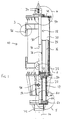
- Fig. 1 shows a piling hammer 10 comprising an anvil member 12 which, in use, is placed against the pile 14 to be driven (indicated by broken lines in Fig. 1).
- the hammer 10 also has a weight 16 and reciprocating means illustrated generally at 18 and operable to reciprocate the weight 16 to impact repeatedly on the anvil 12 to create piling forces.
- Figs. 2a,b,c Before describing the construction of the hammer 10 in more detail, it is appropriate to describe briefly the basic mode of operation of the hammer 10, with reference to Figs. 2a,b,c.
- the hammer 10 is shown in position on a pile 14.
- the weight 16 has been raised to the top of the chamber 20 within which the weight 16 may slide in the manner of a piston. This movement is achieved by the reciprocating means 18 in a manner to be described more fully below.
- the anvil 12 is resting on the pile 14 and projects up through a guide housing 22 through the mouth 24 of the chamber 20, and into the chamber 20.
- the anvil 12 is slidable within the guide housing 22.
- the weight 16 has been allowed to drop to impact on the anvil 12.
- the impact between the weight 16 and the anvil 12 creates a downward piling force, causing the pile 14 to be driven further into the ground.
- the inertia of the chamber 20 and guide housing 22 cause them initially to remain in their position, so that the anvil 12 slides down, relative to the guide housing 22, to the position shown in Fig. 2b.
- Fig. 1 shows circles round various parts of the hammer 10, the contents of the circle being shown also on an enlarged scale in Figs. 3 to 6.
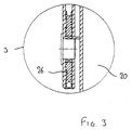
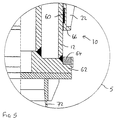
- Fig. 3 shows the content of the circle labelled 3 in Fig. 1, and likewise with the circles 4, 5 and 6, and Figs. 4, 5 and 6.
- the chamber 20 is generally circular in horizontal section. Pulleys 26 on the outside of the chamber 20 allow the hammer 10 to be lifted and supported in position. Within the chamber, the weight 16 is circular in plan and a close sliding fit within the chamber 20, there being bearing rings 18 carried by the weight 16 to provide smooth sliding movement of the weight 16 relative to the chamber 20.
- Reciprocation of the weight 16 is by operation of a hydraulic cylinder 30 which extends down from the top of the chamber 20, into a central, vertical bore 32 in the weight 16.
- the cylinder 32 contains a hydraulic piston controlled by hydraulic fluid supplied through ports 34 and connected to a rod 36 which extends down through the bore 32 to be attached to the weight 16 at the lower face of the weight 16.
- the weight 16 is raised by supplying hydraulic fluid to the cylinder 32 to drive the piston up, pulling the weight 16 up by means of the rod 36.
- appropriate valve arrangements can be used to connect the ports 34 together, to equalise pressure to either side of the piston within the cylinder 32, thereby allowing the weight 16 to fall to impact on the anvil 12.
- connection between the weight 16 and the rod 36 includes a circular flange 38 extending around the bore 32 and trapped between a collar 40 and nut 42 carried by the rod 36.
- Cushion rings 44 of synthetic plastics material such as a urethane are interposed between the flange 38 and the collar 40, and between the flange 38 and the nut 42.
- the cylinder 30 is mounted in the top of the chamber 20 by a similar cushioned flange arrangement including a circular flange 46 extending around the cylinder 30, and trapped between a lid member 48 at the top of the chamber 20, and a fixing ring 50 attached to the lid member 48 by appropriate bolt arrangements.
- cushion rings 52 of a synthetic material such as a urethane are interposed between the flange 46 and the lid member 48, and between the flange 46 and the fixing ring 50.
- the cushion rings 52 serve to damp vibration of the cylinder 30 relative to the lid 48, particularly when the weight 16 impacts on the anvil 12. This supplements the vibration damping provided between the weight 16 and the rod 36 by virtue of the cushion rings 44.
- a further ring 54 of cushioning material is mounted on the under surface of the lid 48 to cushion impact between the weight 16 and the lid 48 at the top of the range of movement of the weight 16.
- the anvil 12 is generally circular in plan and slidable within the guide housing 22, as has been described.
- a retaining pin 56 may project laterally from the guide housing 22 into a slot 58 in the anvil 12, to limit the range of movement of the anvil 12 relative to the guide housing 22.
- the pin 56 is shown at the upper extremity of the slot 58, corresponding to the lowermost position of the anvil 12 relative to the guide housing 22.
- Movement of the anvil 12 within the guide housing 22 is facilitated by bearing rings 60 mounted in the walls of the guide housing 22 and preferably of a synthetic plastics material of low friction characteristic.
- the lowermost extremity of the anvil 12 carries a radial face at 62, on which is mounted a cushion ring 64, against which the lower edge 66 of the housing 22 will bear when the guide housing 22 falls relative to the anvil 12, thereby cushioning the impact between the guide housing 22 and the anvil 12.
- the upper face of the anvil 12 carries a cushion 68 in the form of a large, thick disc of synthetic material, such as a urethane.
- the cushion 68 is positioned so that when the weight 16 falls, the impact on the anvil 12 is not direct, but through the cushion 68.
- a further cushion ring 70 is provided around the lower edge of the chamber walls, against which the weight 16 will rest in the event that the anvil 12 moves down sufficiently, relative to the weight 16, to move clear of the weight 16.
- the anvil 12 carries a seat 72 in the form of a downwardly open recess into which the top of a pile 14 may be received, the recess being of appropriate cross-section to seat closely on the pile 14, to maintain the hammer 10 in correct alignment with the pile 14.
- the impact of the weight and anvil takes place within the chamber 20, which is substantially completely enclosed around the impact. This has been found to be significant in containing noise created by impacts.
- the use of cushioning and bearings as described above is found to further control noise. All surface to surface contact arising during normal operation of the hammer is cushioned by an appropriate body of cushion material.
- the dimensions of the components are chosen to further assist in the process of noise reduction.
- the chamber 20 can be constructed to minimise vibration at an audible frequency, such as by using thick walls, even if the wall thickness is greater than is required to withstand forces experienced during use.
- the hammer of the present invention uses an anvil which is very much heavier.
- a 5 tonne weight would be used with a 1 tonne anvil (a weight ratio of 5:1).
- a 3 tonne weight would be used with a 450kg anvil (a weight ratio of about 6.6:1).
- a weight ratio of no greater than 8:1 is considered beneficial. This significant increase in the anvil weight as compared with the weight itself, produces greater inertia of the anvil.
- the impact will cause the anvil and pile to be driven down between 5mm and 100mm on each impact. This distance will depend on the nature of the ground into which the pile is being driven, and other characteristics of the particular application.
Landscapes
- Engineering & Computer Science (AREA)
- Life Sciences & Earth Sciences (AREA)
- General Life Sciences & Earth Sciences (AREA)
- Mining & Mineral Resources (AREA)
- Paleontology (AREA)
- Civil Engineering (AREA)
- General Engineering & Computer Science (AREA)
- Structural Engineering (AREA)
- Placing Or Removing Of Piles Or Sheet Piles, Or Accessories Thereof (AREA)
Applications Claiming Priority (2)
| Application Number | Priority Date | Filing Date | Title |
|---|---|---|---|
| GB9921755 | 1999-09-16 | ||
| GBGB9921755.6A GB9921755D0 (en) | 1999-09-16 | 1999-09-16 | Piling hammer |
Publications (2)
| Publication Number | Publication Date |
|---|---|
| EP1085130A2 true EP1085130A2 (fr) | 2001-03-21 |
| EP1085130A3 EP1085130A3 (fr) | 2002-10-23 |
Family
ID=10860925
Family Applications (1)
| Application Number | Title | Priority Date | Filing Date |
|---|---|---|---|
| EP00307356A Withdrawn EP1085130A3 (fr) | 1999-09-16 | 2000-08-25 | Marteau de battage de pieux |
Country Status (2)
| Country | Link |
|---|---|
| EP (1) | EP1085130A3 (fr) |
| GB (2) | GB9921755D0 (fr) |
Cited By (4)
| Publication number | Priority date | Publication date | Assignee | Title |
|---|---|---|---|---|
| WO2010046006A1 (fr) * | 2008-10-22 | 2010-04-29 | Menck Gmbh Industriegebiet Moorkaten | Guidage linéaire pour la masse tombante d'un marteau batteur |
| CN109024588A (zh) * | 2018-10-19 | 2018-12-18 | 广东力源液压机械有限公司 | 一种液压锤弹性连接与缓冲控制方法及减震结构 |
| CN113202096A (zh) * | 2021-05-18 | 2021-08-03 | 福建台捷重工机械有限公司 | 一种低噪音液压打桩锤 |
| EP4384665A1 (fr) * | 2021-08-11 | 2024-06-19 | IQIP Holding B.V. | Dispositif d'enfoncement de pieu et suiveur |
Family Cites Families (7)
| Publication number | Priority date | Publication date | Assignee | Title |
|---|---|---|---|---|
| GB1369789A (en) * | 1970-11-17 | 1974-10-09 | Shelbourne H C | Reduction of noise from piling rigs and the like |
| SU628230A1 (ru) * | 1977-05-18 | 1978-10-15 | Научно-Исследовательский Институт Промышленного Строительства | Дизельмолот |
| JPS5681720A (en) * | 1979-12-09 | 1981-07-04 | Koji Mitsuo | Drop hammer |
| DE3107140C2 (de) * | 1981-02-26 | 1985-11-28 | Mannesmann AG, 4000 Düsseldorf | Rammvorrichtung mit einer Schlagvorrichtung |
| NL8202224A (nl) * | 1982-06-02 | 1984-01-02 | Nierstrasz Nv | Hydraulisch werkende heiinrichting. |
| US5117924A (en) * | 1991-01-15 | 1992-06-02 | Berminghammer Corporation Limited | Energy transfer unit for a pile driver |
| JPH11303080A (ja) * | 1998-04-24 | 1999-11-02 | Mitsubishi Heavy Ind Ltd | ガイド装置およびこれを利用する振動杭打機 |
-
1999
- 1999-09-16 GB GBGB9921755.6A patent/GB9921755D0/en not_active Ceased
-
2000
- 2000-08-25 GB GB0020868A patent/GB2354277B/en not_active Expired - Lifetime
- 2000-08-25 EP EP00307356A patent/EP1085130A3/fr not_active Withdrawn
Cited By (5)
| Publication number | Priority date | Publication date | Assignee | Title |
|---|---|---|---|---|
| WO2010046006A1 (fr) * | 2008-10-22 | 2010-04-29 | Menck Gmbh Industriegebiet Moorkaten | Guidage linéaire pour la masse tombante d'un marteau batteur |
| JP2012506506A (ja) * | 2008-10-22 | 2012-03-15 | メンク ゲゼルシヤフト・ミツト・ベシユレンクテル・ハウトウング | 杭打ちハンマーの落下体用の直動ガイド |
| CN109024588A (zh) * | 2018-10-19 | 2018-12-18 | 广东力源液压机械有限公司 | 一种液压锤弹性连接与缓冲控制方法及减震结构 |
| CN113202096A (zh) * | 2021-05-18 | 2021-08-03 | 福建台捷重工机械有限公司 | 一种低噪音液压打桩锤 |
| EP4384665A1 (fr) * | 2021-08-11 | 2024-06-19 | IQIP Holding B.V. | Dispositif d'enfoncement de pieu et suiveur |
Also Published As
| Publication number | Publication date |
|---|---|
| EP1085130A3 (fr) | 2002-10-23 |
| GB2354277B (en) | 2002-05-08 |
| GB0020868D0 (en) | 2000-10-11 |
| GB2354277A (en) | 2001-03-21 |
| GB9921755D0 (en) | 1999-11-17 |
Similar Documents
| Publication | Publication Date | Title |
|---|---|---|
| TWI911159B (zh) | 打樁機總成、控制系統及將一樁打入至地面的方法 | |
| US4465145A (en) | Cushioned drive cap for a pile driver | |
| US5752571A (en) | Apparatus for generating impacts | |
| EP1085130A2 (fr) | Marteau de battage de pieux | |
| JP2008508449A (ja) | 建築部材を設置するための装置および方法 | |
| WO2014137764A1 (fr) | Marteau hydraulique | |
| WO2020263095A1 (fr) | Ensemble batteuse de pieux et son procédé d'utilisation | |
| EP3080357B1 (fr) | Procédé et appareil d'enfoncement de pieux | |
| EP1715105A1 (fr) | Sonnette et méthode pour l'installation d'élément de fondation, et kit de pièces pour assembler une sonnette | |
| NL2023409B1 (en) | Pile-driver and method | |
| NL2023408B1 (en) | Pile-driver and method | |
| CN212582669U (zh) | 一种液压锤 | |
| JPS62173181A (ja) | ブレ−カ | |
| JPH07238529A (ja) | 地盤改良杭造成装置 |
Legal Events
| Date | Code | Title | Description |
|---|---|---|---|
| PUAI | Public reference made under article 153(3) epc to a published international application that has entered the european phase |
Free format text: ORIGINAL CODE: 0009012 |
|
| AK | Designated contracting states |
Kind code of ref document: A2 Designated state(s): AT BE CH CY DE DK ES FI FR GB GR IE IT LI LU MC NL PT SE |
|
| AX | Request for extension of the european patent |
Free format text: AL;LT;LV;MK;RO;SI |
|
| PUAL | Search report despatched |
Free format text: ORIGINAL CODE: 0009013 |
|
| AK | Designated contracting states |
Kind code of ref document: A3 Designated state(s): AT BE CH CY DE DK ES FI FR GB GR IE IT LI LU MC NL PT SE |
|
| AX | Request for extension of the european patent |
Free format text: AL;LT;LV;MK;RO;SI |
|
| RIC1 | Information provided on ipc code assigned before grant |
Free format text: 7E 02D 13/10 A, 7E 02D 7/10 B |
|
| 17P | Request for examination filed |
Effective date: 20030306 |
|
| AKX | Designation fees paid |
Designated state(s): AT BE CH CY DE DK ES FI FR GB GR IE IT LI LU MC NL PT SE |
|
| 17Q | First examination report despatched |
Effective date: 20031016 |
|
| STAA | Information on the status of an ep patent application or granted ep patent |
Free format text: STATUS: THE APPLICATION IS DEEMED TO BE WITHDRAWN |
|
| 18D | Application deemed to be withdrawn |
Effective date: 20050518 |