EP1085149A1 - Fermoir pour valises sacs et objets similaires - Google Patents
Fermoir pour valises sacs et objets similaires Download PDFInfo
- Publication number
- EP1085149A1 EP1085149A1 EP99830574A EP99830574A EP1085149A1 EP 1085149 A1 EP1085149 A1 EP 1085149A1 EP 99830574 A EP99830574 A EP 99830574A EP 99830574 A EP99830574 A EP 99830574A EP 1085149 A1 EP1085149 A1 EP 1085149A1
- Authority
- EP
- European Patent Office
- Prior art keywords
- closing assembly
- pair
- suitcase
- catch
- assembly according
- Prior art date
- Legal status (The legal status is an assumption and is not a legal conclusion. Google has not performed a legal analysis and makes no representation as to the accuracy of the status listed.)
- Granted
Links
Images



Classifications
-
- E—FIXED CONSTRUCTIONS
- E05—LOCKS; KEYS; WINDOW OR DOOR FITTINGS; SAFES
- E05B—LOCKS; ACCESSORIES THEREFOR; HANDCUFFS
- E05B65/00—Locks or fastenings for special use
- E05B65/52—Other locks for chests, boxes, trunks, baskets, travelling bags, or the like
-
- E—FIXED CONSTRUCTIONS
- E05—LOCKS; KEYS; WINDOW OR DOOR FITTINGS; SAFES
- E05B—LOCKS; ACCESSORIES THEREFOR; HANDCUFFS
- E05B37/00—Permutation or combination locks; Puzzle locks
- E05B37/02—Permutation or combination locks; Puzzle locks with tumbler discs or rings arranged on a single axis, each disc being adjustable independently of the others
-
- E—FIXED CONSTRUCTIONS
- E05—LOCKS; KEYS; WINDOW OR DOOR FITTINGS; SAFES
- E05B—LOCKS; ACCESSORIES THEREFOR; HANDCUFFS
- E05B65/00—Locks or fastenings for special use
- E05B65/52—Other locks for chests, boxes, trunks, baskets, travelling bags, or the like
- E05B65/5207—Other locks for chests, boxes, trunks, baskets, travelling bags, or the like characterised by bolt movement
- E05B65/5215—Other locks for chests, boxes, trunks, baskets, travelling bags, or the like characterised by bolt movement sliding
- E05B65/523—Other locks for chests, boxes, trunks, baskets, travelling bags, or the like characterised by bolt movement sliding parallel to the surface on which the lock is mounted
- E05B65/5238—Other locks for chests, boxes, trunks, baskets, travelling bags, or the like characterised by bolt movement sliding parallel to the surface on which the lock is mounted parallel to the wing edge
-
- Y—GENERAL TAGGING OF NEW TECHNOLOGICAL DEVELOPMENTS; GENERAL TAGGING OF CROSS-SECTIONAL TECHNOLOGIES SPANNING OVER SEVERAL SECTIONS OF THE IPC; TECHNICAL SUBJECTS COVERED BY FORMER USPC CROSS-REFERENCE ART COLLECTIONS [XRACs] AND DIGESTS
- Y10—TECHNICAL SUBJECTS COVERED BY FORMER USPC
- Y10S—TECHNICAL SUBJECTS COVERED BY FORMER USPC CROSS-REFERENCE ART COLLECTIONS [XRACs] AND DIGESTS
- Y10S292/00—Closure fasteners
- Y10S292/42—Trunk latches
-
- Y—GENERAL TAGGING OF NEW TECHNOLOGICAL DEVELOPMENTS; GENERAL TAGGING OF CROSS-SECTIONAL TECHNOLOGIES SPANNING OVER SEVERAL SECTIONS OF THE IPC; TECHNICAL SUBJECTS COVERED BY FORMER USPC CROSS-REFERENCE ART COLLECTIONS [XRACs] AND DIGESTS
- Y10—TECHNICAL SUBJECTS COVERED BY FORMER USPC
- Y10T—TECHNICAL SUBJECTS COVERED BY FORMER US CLASSIFICATION
- Y10T292/00—Closure fasteners
- Y10T292/08—Bolts
- Y10T292/0801—Multiple
- Y10T292/0834—Sliding
- Y10T292/0836—Operating means
-
- Y—GENERAL TAGGING OF NEW TECHNOLOGICAL DEVELOPMENTS; GENERAL TAGGING OF CROSS-SECTIONAL TECHNOLOGIES SPANNING OVER SEVERAL SECTIONS OF THE IPC; TECHNICAL SUBJECTS COVERED BY FORMER USPC CROSS-REFERENCE ART COLLECTIONS [XRACs] AND DIGESTS
- Y10—TECHNICAL SUBJECTS COVERED BY FORMER USPC
- Y10T—TECHNICAL SUBJECTS COVERED BY FORMER US CLASSIFICATION
- Y10T292/00—Closure fasteners
- Y10T292/08—Bolts
- Y10T292/0862—Swinging and hooked end, multiple head
-
- Y—GENERAL TAGGING OF NEW TECHNOLOGICAL DEVELOPMENTS; GENERAL TAGGING OF CROSS-SECTIONAL TECHNOLOGIES SPANNING OVER SEVERAL SECTIONS OF THE IPC; TECHNICAL SUBJECTS COVERED BY FORMER USPC CROSS-REFERENCE ART COLLECTIONS [XRACs] AND DIGESTS
- Y10—TECHNICAL SUBJECTS COVERED BY FORMER USPC
- Y10T—TECHNICAL SUBJECTS COVERED BY FORMER US CLASSIFICATION
- Y10T292/00—Closure fasteners
- Y10T292/08—Bolts
- Y10T292/0886—Sliding and swinging
- Y10T292/0892—Multiple head
-
- Y—GENERAL TAGGING OF NEW TECHNOLOGICAL DEVELOPMENTS; GENERAL TAGGING OF CROSS-SECTIONAL TECHNOLOGIES SPANNING OVER SEVERAL SECTIONS OF THE IPC; TECHNICAL SUBJECTS COVERED BY FORMER USPC CROSS-REFERENCE ART COLLECTIONS [XRACs] AND DIGESTS
- Y10—TECHNICAL SUBJECTS COVERED BY FORMER USPC
- Y10T—TECHNICAL SUBJECTS COVERED BY FORMER US CLASSIFICATION
- Y10T292/00—Closure fasteners
- Y10T292/08—Bolts
- Y10T292/0911—Hooked end
- Y10T292/0913—Sliding and swinging
- Y10T292/0914—Operating means
- Y10T292/0915—Cam
-
- Y—GENERAL TAGGING OF NEW TECHNOLOGICAL DEVELOPMENTS; GENERAL TAGGING OF CROSS-SECTIONAL TECHNOLOGIES SPANNING OVER SEVERAL SECTIONS OF THE IPC; TECHNICAL SUBJECTS COVERED BY FORMER USPC CROSS-REFERENCE ART COLLECTIONS [XRACs] AND DIGESTS
- Y10—TECHNICAL SUBJECTS COVERED BY FORMER USPC
- Y10T—TECHNICAL SUBJECTS COVERED BY FORMER US CLASSIFICATION
- Y10T70/00—Locks
- Y10T70/50—Special application
- Y10T70/5009—For portable articles
- Y10T70/5031—Receptacle
- Y10T70/5035—Bag
- Y10T70/5049—Attache or briefcase, portfolio
-
- Y—GENERAL TAGGING OF NEW TECHNOLOGICAL DEVELOPMENTS; GENERAL TAGGING OF CROSS-SECTIONAL TECHNOLOGIES SPANNING OVER SEVERAL SECTIONS OF THE IPC; TECHNICAL SUBJECTS COVERED BY FORMER USPC CROSS-REFERENCE ART COLLECTIONS [XRACs] AND DIGESTS
- Y10—TECHNICAL SUBJECTS COVERED BY FORMER USPC
- Y10T—TECHNICAL SUBJECTS COVERED BY FORMER US CLASSIFICATION
- Y10T70/00—Locks
- Y10T70/50—Special application
- Y10T70/5009—For portable articles
- Y10T70/5031—Receptacle
- Y10T70/5058—Trunk and/or suitcase
Definitions
- the present invention relates to a closing assembly for suitcases, bags and similar.
- the invention relates to a front closing assembly.
- suitcases particularly of the rigid type, which are provided frontally with a closing element comprising a catch formed at one end of a lever swinging around a pivot, which in turn is located at one end of an arm pivoted approximately at the edge of the front surface of one part of the suitcase, typically the base.
- a counter-catch is formed in a corresponding position in the proximity of the edge of the front surface of the other part, typically the lid.
- the lever is also normally associated with a combination or key-operated device.
- the catch With this type of closing element, the catch is brought into a position of engagement with the counter-catch by acting on the swinging element after the lid has been closed on to the base of the suitcase, and a tractive force is exerted on the lid by rotating the lever and the arm until the lever is brought into a closing position in which it is essentially aligned with the outer wall of the base of the case.
- a tractive force is exerted on the lid by rotating the lever and the arm until the lever is brought into a closing position in which it is essentially aligned with the outer wall of the base of the case.
- one object of the present invention was to provide a closing assembly for bags, suitcases and similar, particularly for use as a front closing assembly, which does not have the aforesaid disadvantages.
- this object is achieved by means of a closing assembly for bags, suitcases and similar, comprising at least one pair of catch means associated with a first half-shell of a bag, suitcase or similar and capable of providing a releasable engagement with a corresponding pair of counter-catch means associated with a second half-shell of the bag, suitcase or similar for closing it, characterized by comprising jointly activatable inhibition means for inhibiting the opening of the bag, suitcase or similar, operationally connected to the said at least one pair of catch means and jointly activatable to simultaneously inhibit the release of the engagement with the said pair of counter-catch means.
- a closing assembly comprises a one-piece body 1 designed to be mounted on one of two half-shells forming a suitcase, a bag or similar, for example the half-shell forming a base of the suitcase.
- the one-piece body 1 is designed to be mounted on a front surface of the base of the suitcase, essentially in the proximity of one edge of the front surface, in a median position.
- the one-piece body 1 comprises a central part 5 and two lateral extensions 6 connected to the central part 5 by a cross-piece 7.
- approximately U-shaped slots 9, which are open and flared below, are formed in two opposite lateral walls 8 of the central part 5, and form sockets to receive with a snap-fit and with the possibility of rotation corresponding pivots 110 of a handle 10 for lifting and carrying the suitcase.
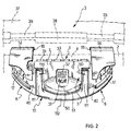
- the handle 10 is shown only in Figures 2, 8 and 9.
- the distance between the lateral walls 8 of the central part 5 and the corresponding adjacent extensions 6 is such that corresponding bars 111 of the handle 10 can be housed therein with sufficient play.
- the central part 5 advantageously has, opposite the cross-piece 7, a surface 50 sloping downwards towards an edge 51 with a generally rounded profile mating with the rounded profile of a cross-piece 112 of the handle 10.
- the extensions 6 extend orthogonally to the cross-piece 7 of the one-piece body 1 further than the central part 5, and their sides opposite the cross-piece 7 have a generally rounded configuration which forms the ideal continuation of the cross-piece 112 of the handle 10. This contributes to the imparting of a harmonious, compact and aesthetically pleasing appearance to the assembly of the one-piece body 1 and the handle 10.
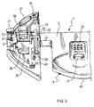
- Each of the two lateral extensions 6 has hinged to it by a first pivot 11 one end of a corresponding arm 12, to whose other end a corresponding lever 14 is hinged by a second pivot 13 ( Figure 3).
- the lateral extensions 6 of the one-piece body 1 are shaped in such a way as to form sockets 15 to receive the corresponding levers 14, in an operating condition in which the assembly is closed.
- One end of the lever 14 is shaped in such a way as to form a catch 16.
- the other end of the lever 14 has, slidably associated with it, a release slider 17 provided on its lower surface with a catch 18 capable of interacting, when the lever 14 is housed in the corresponding socket 15 of the lateral extension 6, with a corresponding counter-catch 19 formed in the base of the socket 15 of the lateral extension 6.
- a socket 41 capable of receiving a projection 40 formed in the corresponding extension 6 when the lever 14 is housed in the socket 15 of the extension 6, is also formed in the release slider 17.
- the release slider 17 is pressed elastically by a spring which is not visible in the drawings, in such a way that the catch 18 is kept in a position such as to ensure the engagement with the counter-catch 19, and that the socket 41 projects towards the corresponding projection 40.
- the release slider 17 is pushed against the elastic pressure of the spring, the catch 18 advances and can disengage the counter-catch 19, and the socket 41 moves away from the projection 40, and therefore the lever 14 can be raised from the corresponding socket 15.
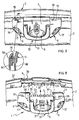
- a locking slider 6 is also slidably housed in the lateral extension 6, and is elastically pushed by a corresponding spring 50 visible in the views from below in Figures 6 and 7 into a position such that, when the lever 14 is positioned within the corresponding socket 15, the catch 18 engaging with the counter-catch 19 and the projection 40 engaging with the socket 41, the locking slider 20 is elastically opposed to the movement of the release slider 17, so that, in order to release the catch 18 from the counter-catch 19, to release the socket 41 from the projection 40 and to release the lever 14, it is necessary to overcome the resistance of the locking slider 20 to the movement of the release slider 17.
- the sliding of the locking sliders 20 in the two lateral extensions 6 can be obstructed by the movement of a pair of arms 22, visible in Figure 4 and in greater detail in Figures 6 and 7, which are slidably housed in corresponding sliding channels formed within the cross-piece 7, transversely with respect to the direction of sliding of the locking sliders 20.
- the two arms 22 act as blockers, selectively releasing ( Figure 7) or blocking ( Figure 6) one end of the sliding channels of the locking sliders 20, thus allowing or obstructing, respectively, the sliding of the locking sliders 20.
- the two arms 22 can be moved simultaneously by means of a single central control slider 23 housed in the central part 5 of the one-piece body and slidable transversely with respect to the arms 22, and consequently parallel to the direction of sliding of the locking sliders 20.
- the central slider 23 comprises a central body 27, with a pair of slots 28 in the opposite side walls 29 of the central body, through which passes a guide pin 30 supported at both ends by the central part 5 of the one-piece body 1.
- the slider 23 is provided with two wings 24, each provided with a slot 25 which is oblique with respect to the direction of sliding of the slider 23.
- the oblique slot 25 slidably houses a projection 250 formed in an enlarged end 26 of the arms 22, in such a way that the movement of advance or withdrawal of the slider 23 in the direction of the arrow A in Figure 5 is converted, by means of the sliding coupling formed by the slots 25 and the projections 250, into the movement of the arms 22 in the orthogonal direction indicated by the arrow B.
- the slider 23 can be operated manually by the user's action on a block 31 projecting from the upper surface of the central part 5 of the one-piece body 1 through an access aperture having suitable dimensions to allow the movement of the block 31.
- a combination device 32 with a dial accessible externally to the user, is also preferably housed in the central part of the one-piece body 1.
- the combination device can be used to block the operation of the slider 23 by preventing its movement in the direction B, and consequently preventing the withdrawal of the arms 22 from the position shown in Figure 6; in this way the locking sliders 20, being unable to slide when the release sliders 17 provided on the levers 14 are pressed, prevents the disengagement of the catches 18 of the levers from the corresponding counter-catches 19, and the disengagement of the sockets 41 from the corresponding projections 40.
- Figures 2 and 8 show in detail the means for joining the closing assembly to the suitcase.
- a plurality of frontally projecting extensions 33 having a generally U-shaped cross section, is formed along the cross-piece of the one-piece body 1. These extensions 33 are designed to be inserted in corresponding sockets 34 of essentially rectangular section aligned along one edge 4 of the base half-shell 2 of a suitcase 3, for example a suitcase of the rigid type.
- the insertion of the extensions 33 into the corresponding sockets 34 is guided by a pair of guide elements 35 consisting essentially of undercuts insertable into two corresponding sockets 36 of matching shape formed frontally in the cross-piece 7, on the two sides of the plurality of extensions 33.
- This enables the closing assembly to be mounted on the suitcase in a fast and simple way, without the need to use additional fixing elements.
- Figure 9 shows the closing assembly according to the present invention attached to the suitcase 3, the latter being open.
- the half-shell 37 forming the lid of the suitcase 3 is initially positioned on the base 2 in such a way that the edges 4 of the base and 38 of the cover meet.
- the catches 16 at the ends of the levers 14 are brought into a position of engagement with corresponding counter-catches 39 formed in suitable positions in the edge 38 of the lid 37.
- the levers 14 and the corresponding arms 12 are rotated about the pivots 11, 13 respectively, while simultaneously exerting a tractive force on the lid 37.
- the release sliders 17 of the levers 14 are pressed to disengage the catches 18 from the corresponding counter-catches 19, and to disengage the sockets 41 from the corresponding projections 40, thus releasing the levers 14 which can then be raised.
- the closing assembly comprising a pair of levers with catches capable of interacting with a corresponding pair of counter-catches, provides a good distribution of forces both during the operation of closing the suitcase and when the suitcase is closed. Moreover, since a one-piece body supporting the pair of levers with catches is provided, the assembly operations are fast and easy, it being unnecessary to mount the pair of levers individually. A further advantage due to the fact that the closing assembly is made in the form of a one-piece body which can be separated from the suitcase lies in the ease of replacement of the assembly in case of malfunction or breakage.
- Yet another advantage of the closing assembly according to the invention lies in the fact that it also acts as a support for the mounting of the handle. This makes it unnecessary to provide further hinge means of the handle on the suitcase.
- the result is also particularly pleasing from the aesthetic point of view.
- the closing assembly according to the invention can be used advantageously for the frontal closing of suitcases, particularly but not exclusively of the rigid type, bags, or similar, on its own or in combination with other closing elements, for example side closing elements.
- the closing assembly according to the invention may comprise a larger number of levers and counter-catches.
- levers with ends in the form of catches and the corresponding counter-catches may have configurations different from those described.
- combination device 32 it would also be possible to use a key-operated device, or more generally any security device operable only by the legitimate owners of the suitcase.
Landscapes
- Purses, Travelling Bags, Baskets, Or Suitcases (AREA)
- Bag Frames (AREA)
Priority Applications (6)
| Application Number | Priority Date | Filing Date | Title |
|---|---|---|---|
| DE69904322T DE69904322T2 (de) | 1999-09-13 | 1999-09-13 | Verschluss für Koffer, Taschen und änliche Gegenstände |
| AT99830574T ATE229121T1 (de) | 1999-09-13 | 1999-09-13 | Verschluss für koffer, taschen und änliche gegenstände |
| EP99830574A EP1085149B1 (fr) | 1999-09-13 | 1999-09-13 | Fermoir pour valises sacs et objets similaires |
| ES99830574T ES2189378T3 (es) | 1999-09-13 | 1999-09-13 | Conjunto de cierre para maletas, bolsas y elementos similares. |
| US09/658,427 US6527306B1 (en) | 1999-09-13 | 2000-09-08 | Closing assembly for suitcases, bags and similar |
| CNB001247565A CN1156638C (zh) | 1999-09-13 | 2000-09-13 | 手提箱和袋及类似物的关闭组件 |
Applications Claiming Priority (1)
| Application Number | Priority Date | Filing Date | Title |
|---|---|---|---|
| EP99830574A EP1085149B1 (fr) | 1999-09-13 | 1999-09-13 | Fermoir pour valises sacs et objets similaires |
Publications (2)
| Publication Number | Publication Date |
|---|---|
| EP1085149A1 true EP1085149A1 (fr) | 2001-03-21 |
| EP1085149B1 EP1085149B1 (fr) | 2002-12-04 |
Family
ID=8243586
Family Applications (1)
| Application Number | Title | Priority Date | Filing Date |
|---|---|---|---|
| EP99830574A Expired - Lifetime EP1085149B1 (fr) | 1999-09-13 | 1999-09-13 | Fermoir pour valises sacs et objets similaires |
Country Status (6)
| Country | Link |
|---|---|
| US (1) | US6527306B1 (fr) |
| EP (1) | EP1085149B1 (fr) |
| CN (1) | CN1156638C (fr) |
| AT (1) | ATE229121T1 (fr) |
| DE (1) | DE69904322T2 (fr) |
| ES (1) | ES2189378T3 (fr) |
Families Citing this family (1)
| Publication number | Priority date | Publication date | Assignee | Title |
|---|---|---|---|---|
| US7331204B1 (en) * | 2006-09-07 | 2008-02-19 | Eminent Luggage Corp. | Combination lock |
Citations (5)
| Publication number | Priority date | Publication date | Assignee | Title |
|---|---|---|---|---|
| US2294120A (en) * | 1941-04-01 | 1942-08-25 | Presto Lock Corp | Latching means for luggage |
| DE805053C (de) * | 1948-10-26 | 1951-05-07 | Friedrich Unteutsch | Verschluss fuer Behaelter, insbesondere Koffer, Aktentaschen, Mappen o. dgl. |
| DE2010085A1 (de) * | 1970-03-04 | 1971-09-16 | Buchmann, Rudolfe , 6800 Mannheim Feudenheim | Schließvorrichtung fur zwei oder drei teilige Behalter oder Koffer mit mehreren Zuhaltestellen und einem Sperrmechanismus |
| US5111918A (en) * | 1990-05-25 | 1992-05-12 | S. Franzen Sohne (Gmbh & Co.) | Rollable suitcase |
| DE9308167U1 (de) * | 1993-06-01 | 1993-07-22 | Cedpo Metal Corp., Changhua | Kombinationsschloß für Koffer |
Family Cites Families (10)
| Publication number | Priority date | Publication date | Assignee | Title |
|---|---|---|---|---|
| US1370941A (en) * | 1919-12-10 | 1921-03-08 | Henry Likley & Company | Locking mechanism |
| US2729088A (en) * | 1953-06-29 | 1956-01-03 | Huot Mfg Company | Double lock for cabinet |
| US3135105A (en) * | 1962-07-23 | 1964-06-02 | Brody Leo | Luggage case |
| US3400562A (en) * | 1965-12-21 | 1968-09-10 | Seymour Products Corp | Latching device |
| US3498657A (en) * | 1966-06-14 | 1970-03-03 | Valextra Spa | Latch means |
| US4547006A (en) * | 1978-06-22 | 1985-10-15 | Superior S.A. | Luggage closing device |
| FR2453258A1 (fr) * | 1979-04-06 | 1980-10-31 | Manzoni Stephane | Dispositif de serrure notamment pour valise |
| US4366686A (en) * | 1980-08-20 | 1983-01-04 | Presto Lock, Inc. | Latching systems particularly for articles of luggage |
| US5557954A (en) * | 1995-06-05 | 1996-09-24 | Ling; Chong-Kuan | Combination lock with dually depressible push buttons |
| US6202455B1 (en) * | 2000-01-24 | 2001-03-20 | Shun-Chang Su | Zipper lock assembly for an article with a zipper having two pull tabs |
-
1999
- 1999-09-13 ES ES99830574T patent/ES2189378T3/es not_active Expired - Lifetime
- 1999-09-13 EP EP99830574A patent/EP1085149B1/fr not_active Expired - Lifetime
- 1999-09-13 DE DE69904322T patent/DE69904322T2/de not_active Expired - Fee Related
- 1999-09-13 AT AT99830574T patent/ATE229121T1/de not_active IP Right Cessation
-
2000
- 2000-09-08 US US09/658,427 patent/US6527306B1/en not_active Expired - Fee Related
- 2000-09-13 CN CNB001247565A patent/CN1156638C/zh not_active Expired - Fee Related
Patent Citations (5)
| Publication number | Priority date | Publication date | Assignee | Title |
|---|---|---|---|---|
| US2294120A (en) * | 1941-04-01 | 1942-08-25 | Presto Lock Corp | Latching means for luggage |
| DE805053C (de) * | 1948-10-26 | 1951-05-07 | Friedrich Unteutsch | Verschluss fuer Behaelter, insbesondere Koffer, Aktentaschen, Mappen o. dgl. |
| DE2010085A1 (de) * | 1970-03-04 | 1971-09-16 | Buchmann, Rudolfe , 6800 Mannheim Feudenheim | Schließvorrichtung fur zwei oder drei teilige Behalter oder Koffer mit mehreren Zuhaltestellen und einem Sperrmechanismus |
| US5111918A (en) * | 1990-05-25 | 1992-05-12 | S. Franzen Sohne (Gmbh & Co.) | Rollable suitcase |
| DE9308167U1 (de) * | 1993-06-01 | 1993-07-22 | Cedpo Metal Corp., Changhua | Kombinationsschloß für Koffer |
Also Published As
| Publication number | Publication date |
|---|---|
| CN1156638C (zh) | 2004-07-07 |
| DE69904322T2 (de) | 2003-08-28 |
| CN1287821A (zh) | 2001-03-21 |
| ATE229121T1 (de) | 2002-12-15 |
| DE69904322D1 (de) | 2003-01-16 |
| US6527306B1 (en) | 2003-03-04 |
| EP1085149B1 (fr) | 2002-12-04 |
| ES2189378T3 (es) | 2003-07-01 |
Similar Documents
| Publication | Publication Date | Title |
|---|---|---|
| US20120067090A1 (en) | Cabinet security system | |
| CN107404986A (zh) | 用于行李件的闭合装置组件 | |
| TW509747B (en) | Handle device | |
| KR960040231A (ko) | 은폐식 슬라이드 파스너용 자동 잠금 슬라이더 | |
| US5816629A (en) | Sliding door latch with self-retracting finger pull | |
| US8739582B2 (en) | Locking arrangement | |
| CA1303867C (fr) | Systeme de securite | |
| US6527306B1 (en) | Closing assembly for suitcases, bags and similar | |
| US6412316B1 (en) | Case lock | |
| US4813251A (en) | Four point locking system for storage cabinets | |
| JPS60105776A (ja) | 組合わせ錠を備えるトランク等用鎖錠装置 | |
| US4761974A (en) | Combination lock for luggage cases | |
| JP2855441B2 (ja) | トランク錠 | |
| US4848111A (en) | Locking device for cases, such as briefcases and the like | |
| US6752437B1 (en) | Fastening mechanism for a cover, door or the like | |
| US6419287B1 (en) | Fastening mechanism for a cover, door or the like | |
| JPS585006Y2 (ja) | 簡易鎖錠装置 | |
| GB2291462A (en) | A coupling with a latchable closing piece | |
| CN113768302A (zh) | 用于家具的打开和/或关闭装置 | |
| KR910006242Y1 (ko) | 손잡이 겸용 자물쇠 뭉치 | |
| US3390555A (en) | Rotating luggage latch | |
| KR200211923Y1 (ko) | 캐비넷용 손잡이 | |
| WO2000048872A1 (fr) | Verrou | |
| JPH10127901A (ja) | パチンコ機の施錠装置 | |
| GB2201726A (en) | Zipper lock for luggage cases |
Legal Events
| Date | Code | Title | Description |
|---|---|---|---|
| PUAI | Public reference made under article 153(3) epc to a published international application that has entered the european phase |
Free format text: ORIGINAL CODE: 0009012 |
|
| 17P | Request for examination filed |
Effective date: 20001117 |
|
| AK | Designated contracting states |
Kind code of ref document: A1 Designated state(s): AT BE CH CY DE DK ES FI FR GB GR IE IT LI LU MC NL PT SE |
|
| AX | Request for extension of the european patent |
Free format text: AL;LT;LV;MK;RO;SI |
|
| 17Q | First examination report despatched |
Effective date: 20010426 |
|
| AKX | Designation fees paid |
Free format text: AT BE CH CY DE DK ES FI FR GB GR IE IT LI LU MC NL PT SE |
|
| GRAG | Despatch of communication of intention to grant |
Free format text: ORIGINAL CODE: EPIDOS AGRA |
|
| GRAG | Despatch of communication of intention to grant |
Free format text: ORIGINAL CODE: EPIDOS AGRA |
|
| GRAH | Despatch of communication of intention to grant a patent |
Free format text: ORIGINAL CODE: EPIDOS IGRA |
|
| GRAH | Despatch of communication of intention to grant a patent |
Free format text: ORIGINAL CODE: EPIDOS IGRA |
|
| GRAA | (expected) grant |
Free format text: ORIGINAL CODE: 0009210 |
|
| AK | Designated contracting states |
Kind code of ref document: B1 Designated state(s): AT BE CH CY DE DK ES FI FR GB GR IE IT LI LU MC NL PT SE |
|
| PG25 | Lapsed in a contracting state [announced via postgrant information from national office to epo] |
Ref country code: NL Free format text: LAPSE BECAUSE OF FAILURE TO SUBMIT A TRANSLATION OF THE DESCRIPTION OR TO PAY THE FEE WITHIN THE PRESCRIBED TIME-LIMIT Effective date: 20021204 Ref country code: LI Free format text: LAPSE BECAUSE OF FAILURE TO SUBMIT A TRANSLATION OF THE DESCRIPTION OR TO PAY THE FEE WITHIN THE PRESCRIBED TIME-LIMIT Effective date: 20021204 Ref country code: GR Free format text: LAPSE BECAUSE OF FAILURE TO SUBMIT A TRANSLATION OF THE DESCRIPTION OR TO PAY THE FEE WITHIN THE PRESCRIBED TIME-LIMIT Effective date: 20021204 Ref country code: FI Free format text: LAPSE BECAUSE OF FAILURE TO SUBMIT A TRANSLATION OF THE DESCRIPTION OR TO PAY THE FEE WITHIN THE PRESCRIBED TIME-LIMIT Effective date: 20021204 Ref country code: CH Free format text: LAPSE BECAUSE OF FAILURE TO SUBMIT A TRANSLATION OF THE DESCRIPTION OR TO PAY THE FEE WITHIN THE PRESCRIBED TIME-LIMIT Effective date: 20021204 Ref country code: AT Free format text: LAPSE BECAUSE OF FAILURE TO SUBMIT A TRANSLATION OF THE DESCRIPTION OR TO PAY THE FEE WITHIN THE PRESCRIBED TIME-LIMIT Effective date: 20021204 |
|
| REF | Corresponds to: |
Ref document number: 229121 Country of ref document: AT Date of ref document: 20021215 Kind code of ref document: T |
|
| REG | Reference to a national code |
Ref country code: GB Ref legal event code: FG4D |
|
| REG | Reference to a national code |
Ref country code: CH Ref legal event code: EP |
|
| REG | Reference to a national code |
Ref country code: IE Ref legal event code: FG4D |
|
| REF | Corresponds to: |
Ref document number: 69904322 Country of ref document: DE Date of ref document: 20030116 |
|
| PG25 | Lapsed in a contracting state [announced via postgrant information from national office to epo] |
Ref country code: SE Free format text: LAPSE BECAUSE OF FAILURE TO SUBMIT A TRANSLATION OF THE DESCRIPTION OR TO PAY THE FEE WITHIN THE PRESCRIBED TIME-LIMIT Effective date: 20030304 Ref country code: DK Free format text: LAPSE BECAUSE OF FAILURE TO SUBMIT A TRANSLATION OF THE DESCRIPTION OR TO PAY THE FEE WITHIN THE PRESCRIBED TIME-LIMIT Effective date: 20030304 |
|
| PG25 | Lapsed in a contracting state [announced via postgrant information from national office to epo] |
Ref country code: PT Free format text: LAPSE BECAUSE OF FAILURE TO SUBMIT A TRANSLATION OF THE DESCRIPTION OR TO PAY THE FEE WITHIN THE PRESCRIBED TIME-LIMIT Effective date: 20030305 |
|
| ET | Fr: translation filed | ||
| NLV1 | Nl: lapsed or annulled due to failure to fulfill the requirements of art. 29p and 29m of the patents act | ||
| REG | Reference to a national code |
Ref country code: CH Ref legal event code: PL |
|
| REG | Reference to a national code |
Ref country code: ES Ref legal event code: FG2A Ref document number: 2189378 Country of ref document: ES Kind code of ref document: T3 |
|
| PG25 | Lapsed in a contracting state [announced via postgrant information from national office to epo] |
Ref country code: LU Free format text: LAPSE BECAUSE OF NON-PAYMENT OF DUE FEES Effective date: 20030913 Ref country code: CY Free format text: LAPSE BECAUSE OF FAILURE TO SUBMIT A TRANSLATION OF THE DESCRIPTION OR TO PAY THE FEE WITHIN THE PRESCRIBED TIME-LIMIT Effective date: 20030913 |
|
| PG25 | Lapsed in a contracting state [announced via postgrant information from national office to epo] |
Ref country code: IE Free format text: LAPSE BECAUSE OF NON-PAYMENT OF DUE FEES Effective date: 20030915 |
|
| PG25 | Lapsed in a contracting state [announced via postgrant information from national office to epo] |
Ref country code: MC Free format text: LAPSE BECAUSE OF NON-PAYMENT OF DUE FEES Effective date: 20030930 |
|
| PLBE | No opposition filed within time limit |
Free format text: ORIGINAL CODE: 0009261 |
|
| STAA | Information on the status of an ep patent application or granted ep patent |
Free format text: STATUS: NO OPPOSITION FILED WITHIN TIME LIMIT |
|
| 26N | No opposition filed |
Effective date: 20030905 |
|
| REG | Reference to a national code |
Ref country code: IE Ref legal event code: MM4A |
|
| PGFP | Annual fee paid to national office [announced via postgrant information from national office to epo] |
Ref country code: GB Payment date: 20060811 Year of fee payment: 8 |
|
| PGFP | Annual fee paid to national office [announced via postgrant information from national office to epo] |
Ref country code: BE Payment date: 20060901 Year of fee payment: 8 |
|
| PGFP | Annual fee paid to national office [announced via postgrant information from national office to epo] |
Ref country code: DE Payment date: 20070921 Year of fee payment: 9 |
|
| PGFP | Annual fee paid to national office [announced via postgrant information from national office to epo] |
Ref country code: IT Payment date: 20070917 Year of fee payment: 9 Ref country code: ES Payment date: 20071015 Year of fee payment: 9 |
|
| BERE | Be: lapsed |
Owner name: *VALIGERIA RONCATO S.P.A. Effective date: 20070930 |
|
| PGFP | Annual fee paid to national office [announced via postgrant information from national office to epo] |
Ref country code: FR Payment date: 20070912 Year of fee payment: 9 |
|
| GBPC | Gb: european patent ceased through non-payment of renewal fee |
Effective date: 20070913 |
|
| PG25 | Lapsed in a contracting state [announced via postgrant information from national office to epo] |
Ref country code: BE Free format text: LAPSE BECAUSE OF NON-PAYMENT OF DUE FEES Effective date: 20070930 |
|
| PG25 | Lapsed in a contracting state [announced via postgrant information from national office to epo] |
Ref country code: GB Free format text: LAPSE BECAUSE OF NON-PAYMENT OF DUE FEES Effective date: 20070913 |
|
| REG | Reference to a national code |
Ref country code: FR Ref legal event code: ST Effective date: 20090529 |
|
| PG25 | Lapsed in a contracting state [announced via postgrant information from national office to epo] |
Ref country code: IT Free format text: LAPSE BECAUSE OF NON-PAYMENT OF DUE FEES Effective date: 20080913 Ref country code: DE Free format text: LAPSE BECAUSE OF NON-PAYMENT OF DUE FEES Effective date: 20090401 |
|
| PG25 | Lapsed in a contracting state [announced via postgrant information from national office to epo] |
Ref country code: FR Free format text: LAPSE BECAUSE OF NON-PAYMENT OF DUE FEES Effective date: 20080930 |
|
| REG | Reference to a national code |
Ref country code: ES Ref legal event code: FD2A Effective date: 20080915 |
|
| PG25 | Lapsed in a contracting state [announced via postgrant information from national office to epo] |
Ref country code: ES Free format text: LAPSE BECAUSE OF NON-PAYMENT OF DUE FEES Effective date: 20080915 |