EP1085197A2 - Luftansaugkanalsystem für Brennkraftmaschinen - Google Patents
Luftansaugkanalsystem für Brennkraftmaschinen Download PDFInfo
- Publication number
- EP1085197A2 EP1085197A2 EP00118592A EP00118592A EP1085197A2 EP 1085197 A2 EP1085197 A2 EP 1085197A2 EP 00118592 A EP00118592 A EP 00118592A EP 00118592 A EP00118592 A EP 00118592A EP 1085197 A2 EP1085197 A2 EP 1085197A2
- Authority
- EP
- European Patent Office
- Prior art keywords
- intake duct
- insert
- duct system
- air intake
- shaft
- Prior art date
- Legal status (The legal status is an assumption and is not a legal conclusion. Google has not performed a legal analysis and makes no representation as to the accuracy of the status listed.)
- Granted
Links
- 238000002485 combustion reaction Methods 0.000 title claims abstract description 12
- 238000005192 partition Methods 0.000 claims abstract description 5
- 238000002347 injection Methods 0.000 description 3
- 239000007924 injection Substances 0.000 description 3
- 238000000034 method Methods 0.000 description 2
- 238000011161 development Methods 0.000 description 1
- 230000018109 developmental process Effects 0.000 description 1
- 229920001971 elastomer Polymers 0.000 description 1
- 239000000806 elastomer Substances 0.000 description 1
- 239000000446 fuel Substances 0.000 description 1
- 239000008240 homogeneous mixture Substances 0.000 description 1
- 238000003780 insertion Methods 0.000 description 1
- 230000037431 insertion Effects 0.000 description 1
- 238000004519 manufacturing process Methods 0.000 description 1
- 238000000465 moulding Methods 0.000 description 1
- 238000007789 sealing Methods 0.000 description 1
- 238000005507 spraying Methods 0.000 description 1
- 238000013517 stratification Methods 0.000 description 1
- 230000001052 transient effect Effects 0.000 description 1
Images


Classifications
-
- F—MECHANICAL ENGINEERING; LIGHTING; HEATING; WEAPONS; BLASTING
- F02—COMBUSTION ENGINES; HOT-GAS OR COMBUSTION-PRODUCT ENGINE PLANTS
- F02M—SUPPLYING COMBUSTION ENGINES IN GENERAL WITH COMBUSTIBLE MIXTURES OR CONSTITUENTS THEREOF
- F02M35/00—Combustion-air cleaners, air intakes, intake silencers, or induction systems specially adapted for, or arranged on, internal-combustion engines
- F02M35/10—Air intakes; Induction systems
- F02M35/10006—Air intakes; Induction systems characterised by the position of elements of the air intake system in direction of the air intake flow, i.e. between ambient air inlet and supply to the combustion chamber
- F02M35/10078—Connections of intake systems to the engine
- F02M35/10085—Connections of intake systems to the engine having a connecting piece, e.g. a flange, between the engine and the air intake being foreseen with a throttle valve, fuel injector, mixture ducts or the like
-
- F—MECHANICAL ENGINEERING; LIGHTING; HEATING; WEAPONS; BLASTING
- F02—COMBUSTION ENGINES; HOT-GAS OR COMBUSTION-PRODUCT ENGINE PLANTS
- F02D—CONTROLLING COMBUSTION ENGINES
- F02D9/00—Controlling engines by throttling air or fuel-and-air induction conduits or exhaust conduits
- F02D9/08—Throttle valves specially adapted therefor; Arrangements of such valves in conduits
- F02D9/10—Throttle valves specially adapted therefor; Arrangements of such valves in conduits having pivotally-mounted flaps
- F02D9/109—Throttle valves specially adapted therefor; Arrangements of such valves in conduits having pivotally-mounted flaps having two or more flaps
-
- F—MECHANICAL ENGINEERING; LIGHTING; HEATING; WEAPONS; BLASTING
- F02—COMBUSTION ENGINES; HOT-GAS OR COMBUSTION-PRODUCT ENGINE PLANTS
- F02M—SUPPLYING COMBUSTION ENGINES IN GENERAL WITH COMBUSTIBLE MIXTURES OR CONSTITUENTS THEREOF
- F02M35/00—Combustion-air cleaners, air intakes, intake silencers, or induction systems specially adapted for, or arranged on, internal-combustion engines
- F02M35/10—Air intakes; Induction systems
- F02M35/10242—Devices or means connected to or integrated into air intakes; Air intakes combined with other engine or vehicle parts
- F02M35/10255—Arrangements of valves; Multi-way valves
-
- F—MECHANICAL ENGINEERING; LIGHTING; HEATING; WEAPONS; BLASTING
- F02—COMBUSTION ENGINES; HOT-GAS OR COMBUSTION-PRODUCT ENGINE PLANTS
- F02M—SUPPLYING COMBUSTION ENGINES IN GENERAL WITH COMBUSTIBLE MIXTURES OR CONSTITUENTS THEREOF
- F02M35/00—Combustion-air cleaners, air intakes, intake silencers, or induction systems specially adapted for, or arranged on, internal-combustion engines
- F02M35/10—Air intakes; Induction systems
- F02M35/104—Intake manifolds
- F02M35/108—Intake manifolds with primary and secondary intake passages
-
- F—MECHANICAL ENGINEERING; LIGHTING; HEATING; WEAPONS; BLASTING
- F02—COMBUSTION ENGINES; HOT-GAS OR COMBUSTION-PRODUCT ENGINE PLANTS
- F02M—SUPPLYING COMBUSTION ENGINES IN GENERAL WITH COMBUSTIBLE MIXTURES OR CONSTITUENTS THEREOF
- F02M35/00—Combustion-air cleaners, air intakes, intake silencers, or induction systems specially adapted for, or arranged on, internal-combustion engines
- F02M35/10—Air intakes; Induction systems
- F02M35/104—Intake manifolds
- F02M35/112—Intake manifolds for engines with cylinders all in one line
-
- F—MECHANICAL ENGINEERING; LIGHTING; HEATING; WEAPONS; BLASTING
- F02—COMBUSTION ENGINES; HOT-GAS OR COMBUSTION-PRODUCT ENGINE PLANTS
- F02B—INTERNAL-COMBUSTION PISTON ENGINES; COMBUSTION ENGINES IN GENERAL
- F02B31/00—Modifying induction systems for imparting a rotation to the charge in the cylinder
- F02B31/08—Modifying induction systems for imparting a rotation to the charge in the cylinder having multiple air inlets
- F02B31/085—Modifying induction systems for imparting a rotation to the charge in the cylinder having multiple air inlets having two inlet valves
-
- Y—GENERAL TAGGING OF NEW TECHNOLOGICAL DEVELOPMENTS; GENERAL TAGGING OF CROSS-SECTIONAL TECHNOLOGIES SPANNING OVER SEVERAL SECTIONS OF THE IPC; TECHNICAL SUBJECTS COVERED BY FORMER USPC CROSS-REFERENCE ART COLLECTIONS [XRACs] AND DIGESTS
- Y02—TECHNOLOGIES OR APPLICATIONS FOR MITIGATION OR ADAPTATION AGAINST CLIMATE CHANGE
- Y02T—CLIMATE CHANGE MITIGATION TECHNOLOGIES RELATED TO TRANSPORTATION
- Y02T10/00—Road transport of goods or passengers
- Y02T10/10—Internal combustion engine [ICE] based vehicles
- Y02T10/12—Improving ICE efficiencies
Definitions
- the invention relates to an air intake duct system according to the preamble of claim 1.
- Air intake duct systems of this type are used for gasoline and diesel internal combustion engines which work with direct injection.
- Direct injection has the potential to significantly reduce fuel consumption and is therefore an important building block for the necessary reduction in traffic-related CO 2 emissions.
- the transient change between charge stratification at part load and operation with a homogeneous mixture at full load results in special requirements for engine management, e.g. . B. swirl flaps of the air intake duct system are controlled depending on the load and / or speed. This places high demands on controllability and service life, which cannot be achieved with conventional air intake duct systems.
- the object of the invention is to find measures with which easy controllability of the swirl flaps and an extended service life are reachable.
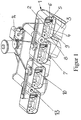
- Fig. 1 shows schematically an air intake duct system 1 for internal combustion engines with a Distribution section 2 of a leading to each individual cylinder of the internal combustion engine Individual intake duct 3 in two individual ducts 4, 5, one of which is through a swirl flap 6 can be completed.
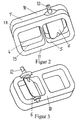
- Air intake duct system 1 it is now provided that the division section 2 as Insert 7, shown in Fig. 2, formed and in an insert shaft 8 on Air intake duct system 1 is used, which has a connecting flange 9 to the cylinder head Internal combustion engine forms.
- the insert 7 is composed of two Insert halves 10, 11 is formed.
- the swirl flap can Insert 6 and hold it there.
- the insert 7 has a stub shaft 12 which with the Swirl flap 6 is connected and through a slot in the wall of the insert shaft 8 protrudes outwards.
- This measure enables the insertion of the insert 7 at after externally protruding shaft stub 12.
- the shaft stub 12 can also, as in FIG. 4 is shown from the outside in the swirl flap 6 designed as a clutch.
- the stub shaft 12 of each insert 7 is a Drive connection 13 connected to a steep 14, it can be provided that Elements of the drive connection 13 and the actuator 14 in one onto the stub shafts 12 attached cassette part are arranged, or alternatively, that in pairs arranged shaft ends 12 via a drive connection 13 and one shaft end 12 each of the pairs arranged via a further drive connection 13 with the actuator 14 are connected.
- the insert 7 can have a streamlined contour Individual channels 4, 5 have, for. B. an inlet funnel 15.
- a particular advantage of the air intake duct system according to the invention has been shown that by using other insert designs, e.g. B. also without swirl flap 6 or without partition section 2 for normal manifold injection engines, a larger one Can cover the number of versions with the same air intake duct base system.
- Lever rods, gears, toothed belts, etc. can be used as the drive connection.
- the flange 9 has an elastomer molding 16 which acts as an axial and radial seal, that in the present embodiment, the insert 7 compared to the seals cylinder head shown.
- the insert 7 can also in the same way be sealed off from the individual intake duct 3.
- the stub shaft 12 is in the present embodiment by a shaft seal 17 sealed against the connecting flange 9.
- FIG. 5 shows a further embodiment of the insert 7, which is now in front of the Inserted into the connecting flange 9 is lipped together. Because the division level 18 of the insert halves 10, 11 is perpendicular to the air flow direction, the Shaft sealing ring 17 no longer in the division plane 18 and is therefore essential less wear and tear. Otherwise, it is also conceivable the insert 7 with the Swirl flap 6 in one spraying process, the so-called 2-component process to manufacture. In addition, it should be clear that, if desired, the insert can also have only one channel with a swirl flap.
Landscapes
- Engineering & Computer Science (AREA)
- Chemical & Material Sciences (AREA)
- Combustion & Propulsion (AREA)
- Mechanical Engineering (AREA)
- General Engineering & Computer Science (AREA)
- Cylinder Crankcases Of Internal Combustion Engines (AREA)
Abstract
Description
eine schematische Darstellung eines Luftansaugkanalsystems einer Brennkraftmaschine mit abgeschnittenen Einzelansaugkanälen,
ein Einsatzstück als Einzelteil,
eine Einsatzhälfte eines Einsatzstückes mit eingelegter Drallklappe,
einen geschnittenen Einsatzschacht mit Einsatzstück,
eine weitere Ausführungsform des Einsatzstückes.
Claims (7)
- Luftansaugkanalsystem 1 für Brennkraftmaschinen mit einem Aufteilungsabschnitt 2 eines zu jedem einzelnen Zylinder der Brennkraftmaschine führenden Einzelansaugkanals 3 in zwei Einzelkanäle 4, 5, von denen einer durch eine Drallklappe 6 abgeschlossen werden kann, dadurch gekennzeichnet, daß der Aufteilungsabschnitt (2) als Einsatzstück (7) ausgebildet ist, das in einen Einsatzschacht (8) am Luftansaugkanalsystem (1) eingesetzt ist und einen Anschlußflansch (9) zum Zylinderkopf der Brennkraftmaschine hin bildet.
- Luftansaugkanalsystem nach Anspruch 1, dadurch gekennzeichnet, daß das Einsatzstück (7) aus zwei zusammengesetzten Einsatzhälften (10, 11) gebildet ist.
- Luftansaugkanalsystem nach Anspruch 2, dadurch gekennzeichnet, daß das Einsatzstück (7) einen Wellenstumpf (12) aufweist, der mit der Drallklappe (6) verbunden ist und durch einen Schlitz in der Wandung des Einsatzschachtes (8) nach außen ragt.
- Luftansaugkanalsystem nach Anspruch 2, dadurch gekennzeichnet, daß das Einsatzstück (7) einen Wellenstumpf (12) aufweist, der mit der als Kupplung ausgeführten Drallklappe (6) verbunden ist und durch eine Öffnung in der Wandung des Einsatzschachtes (8) nach außen ragt.
- Luftansaugkanalsystem nach Anspruch 3 oder 4, dadurch gekennzeichnet, daß der Wellenstumpf (12) jedes Einsatzstückes (7) über eine Antriebsverbindung (13) mit einem Steller (14) verbunden ist.
- Luftansaugkanalsystem nach Anspruch 5, dadurch gekennzeichnet, daß Elemente der Antriebsverbindung (13) und des Stellers (14) in einem auf die Wellenstümpfe (12) aufgesetzten Kassettenteil angeordnet sind.
- Luftansaugkanalsystem nach Anspruch 5, dadurch gekennzeichnet, daß jeweils paarweise angeordnete Wellenstümpfe (12) über eine Antriebsverbindung (13) und je ein Wellenstumpf (12) der paarweise angeordneten über eine Antriebsverbindung (13) mit dem Steller (14) verbunden sind.
Applications Claiming Priority (2)
| Application Number | Priority Date | Filing Date | Title |
|---|---|---|---|
| DE19944623A DE19944623A1 (de) | 1999-09-17 | 1999-09-17 | Luftansaugkanalsystem für Brennkraftmaschinen |
| DE19944623 | 1999-09-17 |
Publications (3)
| Publication Number | Publication Date |
|---|---|
| EP1085197A2 true EP1085197A2 (de) | 2001-03-21 |
| EP1085197A3 EP1085197A3 (de) | 2001-12-19 |
| EP1085197B1 EP1085197B1 (de) | 2002-10-09 |
Family
ID=7922388
Family Applications (1)
| Application Number | Title | Priority Date | Filing Date |
|---|---|---|---|
| EP00118592A Expired - Lifetime EP1085197B1 (de) | 1999-09-17 | 2000-08-28 | Luftansaugkanalsystem für Brennkraftmaschinen |
Country Status (3)
| Country | Link |
|---|---|
| EP (1) | EP1085197B1 (de) |
| DE (2) | DE19944623A1 (de) |
| ES (1) | ES2182750T3 (de) |
Cited By (8)
| Publication number | Priority date | Publication date | Assignee | Title |
|---|---|---|---|---|
| EP1251253A3 (de) * | 2001-04-20 | 2003-07-09 | Filterwerk Mann + Hummel Gmbh | Schaltverband zum Verschluss von Saugkanälen einer Ansaugvorrichtung |
| EP1988264A1 (de) * | 2007-05-02 | 2008-11-05 | Mann+Hummel Gmbh | Lufteinlassverteiler mit Einsatz zur Plenumsreduzierung |
| EP2148078A1 (de) * | 2008-07-24 | 2010-01-27 | Magneti Marelli Powertrain S.p.A. | Saugverteiler mit Zwischenflansch mit Dichtungen |
| EP2148060A1 (de) * | 2008-07-24 | 2010-01-27 | Magneti Marelli Powertrain S.p.A. | Saugrohr mit einem Drallsystems für einen Verbrennungsmotor |
| DE102004013309B4 (de) * | 2004-03-17 | 2015-09-24 | Mahle Filtersysteme Gmbh | Sauganlage für eine Brennkraftmaschine |
| EP2785999B1 (de) | 2011-11-28 | 2015-12-30 | Valeo Systèmes de Contrôle Moteur | Ansaugsystem für einen motor eines fahrzeugs |
| WO2016110524A1 (de) * | 2015-01-07 | 2016-07-14 | Volkswagen Aktiengesellschaft | Motoranordnung mit einem zylinderkopf und einem stromaufwärts des zylinderkopfes angeordneten flansch |
| CN112796911A (zh) * | 2020-12-21 | 2021-05-14 | 中国船舶重工集团公司第七一一研究所 | 一种用于船舶发动机的可变容积进气箱和动力系统 |
Families Citing this family (3)
| Publication number | Priority date | Publication date | Assignee | Title |
|---|---|---|---|---|
| DE10119280A1 (de) * | 2001-04-20 | 2002-11-07 | Mann & Hummel Filter | Ansaugvorrichtung |
| DE10153131A1 (de) * | 2001-10-27 | 2003-05-15 | Pierburg Gmbh | Klappe für Luftansaugsysteme |
| DE102004010555B4 (de) * | 2004-03-04 | 2006-02-09 | Pierburg Gmbh | Klappenlagerbefestigung |
Family Cites Families (5)
| Publication number | Priority date | Publication date | Assignee | Title |
|---|---|---|---|---|
| JPS595769B2 (ja) * | 1978-10-06 | 1984-02-07 | 本田技研工業株式会社 | 高出力型エンジン |
| DE19504382A1 (de) * | 1995-02-10 | 1996-08-14 | Mann & Hummel Filter | Ansaugsystem |
| DE19707599A1 (de) * | 1997-02-26 | 1998-08-27 | Knecht Filterwerke Gmbh | Drosselklappen-Einrichtung für eine Saugsrohranlage eines Verbrennungsmotors |
| DE19728078C2 (de) * | 1997-07-02 | 2002-11-21 | Bosch Gmbh Robert | Vorrichtung zum Ansaugen von Luft |
| AT2743U1 (de) * | 1998-05-07 | 1999-03-25 | Avl List Gmbh | Einlassleitungsanordnung für eine brennkraftmaschine |
-
1999
- 1999-09-17 DE DE19944623A patent/DE19944623A1/de not_active Withdrawn
-
2000
- 2000-08-28 ES ES00118592T patent/ES2182750T3/es not_active Expired - Lifetime
- 2000-08-28 DE DE50000617T patent/DE50000617D1/de not_active Expired - Lifetime
- 2000-08-28 EP EP00118592A patent/EP1085197B1/de not_active Expired - Lifetime
Cited By (13)
| Publication number | Priority date | Publication date | Assignee | Title |
|---|---|---|---|---|
| US6823838B2 (en) | 2001-04-20 | 2004-11-30 | Filterwerk Mann & Hummel Gmbh | Switching assembly for closing intake lines of an air intake device and intake device incorporating same |
| EP1251253A3 (de) * | 2001-04-20 | 2003-07-09 | Filterwerk Mann + Hummel Gmbh | Schaltverband zum Verschluss von Saugkanälen einer Ansaugvorrichtung |
| DE102004013309B4 (de) * | 2004-03-17 | 2015-09-24 | Mahle Filtersysteme Gmbh | Sauganlage für eine Brennkraftmaschine |
| US7886713B2 (en) | 2007-05-02 | 2011-02-15 | Mann + Hummel Gmbh | Lower intake manifold with charge motion control valve |
| EP1988264A1 (de) * | 2007-05-02 | 2008-11-05 | Mann+Hummel Gmbh | Lufteinlassverteiler mit Einsatz zur Plenumsreduzierung |
| EP2148078A1 (de) * | 2008-07-24 | 2010-01-27 | Magneti Marelli Powertrain S.p.A. | Saugverteiler mit Zwischenflansch mit Dichtungen |
| US7856957B2 (en) | 2008-07-24 | 2010-12-28 | MAGNETI MARELLI S.p.A. | Intake manifold with a swirl system for an internal combustion engine |
| EP2148060A1 (de) * | 2008-07-24 | 2010-01-27 | Magneti Marelli Powertrain S.p.A. | Saugrohr mit einem Drallsystems für einen Verbrennungsmotor |
| EP2785999B1 (de) | 2011-11-28 | 2015-12-30 | Valeo Systèmes de Contrôle Moteur | Ansaugsystem für einen motor eines fahrzeugs |
| US9617956B2 (en) | 2011-11-28 | 2017-04-11 | Valeo Systemes De Controle Moteur | Gas intake system for a vehicle engine |
| EP2785999B2 (de) † | 2011-11-28 | 2023-07-12 | Valeo Systèmes de Contrôle Moteur | Ansaugsystem für einen motor eines fahrzeugs |
| WO2016110524A1 (de) * | 2015-01-07 | 2016-07-14 | Volkswagen Aktiengesellschaft | Motoranordnung mit einem zylinderkopf und einem stromaufwärts des zylinderkopfes angeordneten flansch |
| CN112796911A (zh) * | 2020-12-21 | 2021-05-14 | 中国船舶重工集团公司第七一一研究所 | 一种用于船舶发动机的可变容积进气箱和动力系统 |
Also Published As
| Publication number | Publication date |
|---|---|
| ES2182750T3 (es) | 2003-03-16 |
| EP1085197A3 (de) | 2001-12-19 |
| DE19944623A1 (de) | 2001-03-22 |
| DE50000617D1 (de) | 2002-11-14 |
| EP1085197B1 (de) | 2002-10-09 |
Similar Documents
| Publication | Publication Date | Title |
|---|---|---|
| DE2353925C3 (de) | Vorrichtung zur Überwachung und Steuerung von Verunreinigungen bei einer Verbrennungskraftmaschine | |
| DE102014109899B4 (de) | Verbrennungsmotor mit einem Motoreinlasskrümmer mit AGR-Luftströmungsverteilung | |
| EP1157200B1 (de) | Luftansaugsystem für eine brennkraftmaschine | |
| DE4402048A1 (de) | Integriertes Ansaugsystem | |
| DE102014100739B4 (de) | Teilweise integrierter abgaskrümmer | |
| EP1085197B1 (de) | Luftansaugkanalsystem für Brennkraftmaschinen | |
| DE102004055571A1 (de) | Abgasturbolader für eine Brennkraftmaschine | |
| DE19614474B4 (de) | Luftansaugkanalsystem für Brennkraftmaschinen | |
| DE2831694A1 (de) | Verbrennungskraftmotor und zwischenflansch fuer einen solchen | |
| DE3139309A1 (de) | Brennkraftmaschine | |
| DE8914049U1 (de) | Luftansaugkanalsystem für Brennkraftmaschinen | |
| DE19636806A1 (de) | Luftansaugrohr für Brennkraftmaschinen | |
| DE3040472C2 (de) | Brennkraftmaschine | |
| DE19507354B4 (de) | Saugmodul für einen Ottomotor | |
| EP1241344A2 (de) | Luftansaugkanalsystem für eine Brennkraftmaschine | |
| EP0580039A1 (de) | Brennkraftmaschine mit Hubkolben und innerer Verbrennung, insbesondere Dieselmotor | |
| DE69910269T2 (de) | Brennkraftmaschine mit einer kompakten Ansaugeinrichtung | |
| EP1001147A2 (de) | Viertakt-brennkraftmaschine mit mindestens zwei Einlassventilen pro Zylinder | |
| DE3137453A1 (de) | Ansauganordnung fuer eine brennkraftmaschine | |
| DE102004002641B4 (de) | Modulare Ansaugvorrichtung | |
| DE602004005062T2 (de) | Vergaser | |
| DE19651642A1 (de) | Lufteinlaßkanalsystem für Brennkraftmaschinen | |
| EP1020635B1 (de) | Brennluftansaugrohrabschnitt für Dieselbrennkraftmaschinen | |
| DE3007370A1 (de) | Geteilter verbrennungsmotor | |
| DE3786164T2 (de) | Hochleistungsauspuffanlage fuer brennkraftmaschine. |
Legal Events
| Date | Code | Title | Description |
|---|---|---|---|
| PUAI | Public reference made under article 153(3) epc to a published international application that has entered the european phase |
Free format text: ORIGINAL CODE: 0009012 |
|
| 17P | Request for examination filed |
Effective date: 20000828 |
|
| AK | Designated contracting states |
Kind code of ref document: A2 Designated state(s): DE ES FR GB IT Kind code of ref document: A2 Designated state(s): AT BE CH CY DE DK ES FI FR GB GR IE IT LI LU MC NL PT SE |
|
| AX | Request for extension of the european patent |
Free format text: AL;LT;LV;MK;RO;SI |
|
| PUAL | Search report despatched |
Free format text: ORIGINAL CODE: 0009013 |
|
| AK | Designated contracting states |
Kind code of ref document: A3 Designated state(s): AT BE CH CY DE DK ES FI FR GB GR IE IT LI LU MC NL PT SE |
|
| AX | Request for extension of the european patent |
Free format text: AL;LT;LV;MK;RO;SI |
|
| RIC1 | Information provided on ipc code assigned before grant |
Free format text: 7F 02M 35/108 A, 7F 02D 9/10 B |
|
| 17Q | First examination report despatched |
Effective date: 20020201 |
|
| GRAG | Despatch of communication of intention to grant |
Free format text: ORIGINAL CODE: EPIDOS AGRA |
|
| GRAG | Despatch of communication of intention to grant |
Free format text: ORIGINAL CODE: EPIDOS AGRA |
|
| GRAH | Despatch of communication of intention to grant a patent |
Free format text: ORIGINAL CODE: EPIDOS IGRA |
|
| RAP1 | Party data changed (applicant data changed or rights of an application transferred) |
Owner name: PIERBURG GMBH |
|
| GRAH | Despatch of communication of intention to grant a patent |
Free format text: ORIGINAL CODE: EPIDOS IGRA |
|
| GRAA | (expected) grant |
Free format text: ORIGINAL CODE: 0009210 |
|
| AKX | Designation fees paid |
Free format text: DE ES FR GB IT |
|
| AK | Designated contracting states |
Kind code of ref document: B1 Designated state(s): DE ES FR GB IT |
|
| REG | Reference to a national code |
Ref country code: GB Ref legal event code: FG4D Free format text: NOT ENGLISH |
|
| REG | Reference to a national code |
Ref country code: IE Ref legal event code: FG4D Free format text: GERMAN |
|
| REF | Corresponds to: |
Ref document number: 50000617 Country of ref document: DE Date of ref document: 20021114 |
|
| GBT | Gb: translation of ep patent filed (gb section 77(6)(a)/1977) |
Effective date: 20030106 |
|
| REG | Reference to a national code |
Ref country code: ES Ref legal event code: FG2A Ref document number: 2182750 Country of ref document: ES Kind code of ref document: T3 |
|
| ET | Fr: translation filed | ||
| REG | Reference to a national code |
Ref country code: IE Ref legal event code: FD4D Ref document number: 1085197E Country of ref document: IE |
|
| PLBE | No opposition filed within time limit |
Free format text: ORIGINAL CODE: 0009261 |
|
| STAA | Information on the status of an ep patent application or granted ep patent |
Free format text: STATUS: NO OPPOSITION FILED WITHIN TIME LIMIT |
|
| 26N | No opposition filed |
Effective date: 20030710 |
|
| PGFP | Annual fee paid to national office [announced via postgrant information from national office to epo] |
Ref country code: GB Payment date: 20060824 Year of fee payment: 7 |
|
| PGFP | Annual fee paid to national office [announced via postgrant information from national office to epo] |
Ref country code: ES Payment date: 20060830 Year of fee payment: 7 |
|
| GBPC | Gb: european patent ceased through non-payment of renewal fee |
Effective date: 20070828 |
|
| REG | Reference to a national code |
Ref country code: ES Ref legal event code: FD2A Effective date: 20070829 |
|
| PG25 | Lapsed in a contracting state [announced via postgrant information from national office to epo] |
Ref country code: GB Free format text: LAPSE BECAUSE OF NON-PAYMENT OF DUE FEES Effective date: 20070828 |
|
| PG25 | Lapsed in a contracting state [announced via postgrant information from national office to epo] |
Ref country code: ES Free format text: LAPSE BECAUSE OF NON-PAYMENT OF DUE FEES Effective date: 20070829 |
|
| PGFP | Annual fee paid to national office [announced via postgrant information from national office to epo] |
Ref country code: FR Payment date: 20100901 Year of fee payment: 11 Ref country code: IT Payment date: 20100825 Year of fee payment: 11 |
|
| PGFP | Annual fee paid to national office [announced via postgrant information from national office to epo] |
Ref country code: DE Payment date: 20100922 Year of fee payment: 11 |
|
| REG | Reference to a national code |
Ref country code: FR Ref legal event code: ST Effective date: 20120430 |
|
| PG25 | Lapsed in a contracting state [announced via postgrant information from national office to epo] |
Ref country code: IT Free format text: LAPSE BECAUSE OF NON-PAYMENT OF DUE FEES Effective date: 20110828 |
|
| PG25 | Lapsed in a contracting state [announced via postgrant information from national office to epo] |
Ref country code: FR Free format text: LAPSE BECAUSE OF NON-PAYMENT OF DUE FEES Effective date: 20110831 |
|
| PG25 | Lapsed in a contracting state [announced via postgrant information from national office to epo] |
Ref country code: DE Free format text: LAPSE BECAUSE OF NON-PAYMENT OF DUE FEES Effective date: 20130301 |
|
| REG | Reference to a national code |
Ref country code: DE Ref legal event code: R119 Ref document number: 50000617 Country of ref document: DE Effective date: 20130301 |