EP1085213B1 - Motopompe à rotor noyé et plaque de montage - Google Patents
Motopompe à rotor noyé et plaque de montage Download PDFInfo
- Publication number
- EP1085213B1 EP1085213B1 EP00119886A EP00119886A EP1085213B1 EP 1085213 B1 EP1085213 B1 EP 1085213B1 EP 00119886 A EP00119886 A EP 00119886A EP 00119886 A EP00119886 A EP 00119886A EP 1085213 B1 EP1085213 B1 EP 1085213B1
- Authority
- EP
- European Patent Office
- Prior art keywords
- accordance
- base plate
- rotary pump
- pump
- stator
- Prior art date
- Legal status (The legal status is an assumption and is not a legal conclusion. Google has not performed a legal analysis and makes no representation as to the accuracy of the status listed.)
- Expired - Lifetime
Links
- 239000004033 plastic Substances 0.000 claims description 9
- 238000007789 sealing Methods 0.000 claims description 8
- 238000001816 cooling Methods 0.000 claims description 6
- 239000002184 metal Substances 0.000 claims description 5
- 238000010438 heat treatment Methods 0.000 claims description 2
- 239000004065 semiconductor Substances 0.000 claims description 2
- 238000004804 winding Methods 0.000 claims description 2
- 229920002994 synthetic fiber Polymers 0.000 claims 2
- 230000005611 electricity Effects 0.000 claims 1
- 238000004519 manufacturing process Methods 0.000 description 7
- 238000010276 construction Methods 0.000 description 2
- 230000009286 beneficial effect Effects 0.000 description 1
- 238000004512 die casting Methods 0.000 description 1
- 238000006073 displacement reaction Methods 0.000 description 1
- 230000002349 favourable effect Effects 0.000 description 1
- 230000017525 heat dissipation Effects 0.000 description 1
- 238000002347 injection Methods 0.000 description 1
- 239000007924 injection Substances 0.000 description 1
- 238000009413 insulation Methods 0.000 description 1
- 238000012423 maintenance Methods 0.000 description 1
- 239000002991 molded plastic Substances 0.000 description 1
- 238000005457 optimization Methods 0.000 description 1
- 238000010079 rubber tapping Methods 0.000 description 1
- 230000001360 synchronised effect Effects 0.000 description 1
- 239000002918 waste heat Substances 0.000 description 1
- XLYOFNOQVPJJNP-UHFFFAOYSA-N water Substances O XLYOFNOQVPJJNP-UHFFFAOYSA-N 0.000 description 1
Images

Classifications
-
- H—ELECTRICITY
- H02—GENERATION; CONVERSION OR DISTRIBUTION OF ELECTRIC POWER
- H02K—DYNAMO-ELECTRIC MACHINES
- H02K5/00—Casings; Enclosures; Supports
- H02K5/04—Casings or enclosures characterised by the shape, form or construction thereof
- H02K5/12—Casings or enclosures characterised by the shape, form or construction thereof specially adapted for operating in liquid or gas
- H02K5/128—Casings or enclosures characterised by the shape, form or construction thereof specially adapted for operating in liquid or gas using air-gap sleeves or air-gap discs
-
- F—MECHANICAL ENGINEERING; LIGHTING; HEATING; WEAPONS; BLASTING
- F04—POSITIVE - DISPLACEMENT MACHINES FOR LIQUIDS; PUMPS FOR LIQUIDS OR ELASTIC FLUIDS
- F04D—NON-POSITIVE-DISPLACEMENT PUMPS
- F04D13/00—Pumping installations or systems
- F04D13/02—Units comprising pumps and their driving means
- F04D13/06—Units comprising pumps and their driving means the pump being electrically driven
- F04D13/0606—Canned motor pumps
- F04D13/0613—Special connection between the rotor compartments
-
- F—MECHANICAL ENGINEERING; LIGHTING; HEATING; WEAPONS; BLASTING
- F04—POSITIVE - DISPLACEMENT MACHINES FOR LIQUIDS; PUMPS FOR LIQUIDS OR ELASTIC FLUIDS
- F04D—NON-POSITIVE-DISPLACEMENT PUMPS
- F04D29/00—Details, component parts, or accessories
- F04D29/02—Selection of particular materials
- F04D29/026—Selection of particular materials especially adapted for liquid pumps
-
- F—MECHANICAL ENGINEERING; LIGHTING; HEATING; WEAPONS; BLASTING
- F04—POSITIVE - DISPLACEMENT MACHINES FOR LIQUIDS; PUMPS FOR LIQUIDS OR ELASTIC FLUIDS
- F04D—NON-POSITIVE-DISPLACEMENT PUMPS
- F04D29/00—Details, component parts, or accessories
- F04D29/58—Cooling; Heating; Diminishing heat transfer
- F04D29/586—Cooling; Heating; Diminishing heat transfer specially adapted for liquid pumps
- F04D29/588—Cooling; Heating; Diminishing heat transfer specially adapted for liquid pumps cooling or heating the machine
-
- F—MECHANICAL ENGINEERING; LIGHTING; HEATING; WEAPONS; BLASTING
- F04—POSITIVE - DISPLACEMENT MACHINES FOR LIQUIDS; PUMPS FOR LIQUIDS OR ELASTIC FLUIDS
- F04D—NON-POSITIVE-DISPLACEMENT PUMPS
- F04D29/00—Details, component parts, or accessories
- F04D29/60—Mounting; Assembling; Disassembling
- F04D29/62—Mounting; Assembling; Disassembling of radial or helico-centrifugal pumps
- F04D29/628—Mounting; Assembling; Disassembling of radial or helico-centrifugal pumps especially adapted for liquid pumps
-
- H—ELECTRICITY
- H02—GENERATION; CONVERSION OR DISTRIBUTION OF ELECTRIC POWER
- H02K—DYNAMO-ELECTRIC MACHINES
- H02K11/00—Structural association of dynamo-electric machines with electric components or with devices for shielding, monitoring or protection
- H02K11/30—Structural association with control circuits or drive circuits
- H02K11/33—Drive circuits, e.g. power electronics
-
- F—MECHANICAL ENGINEERING; LIGHTING; HEATING; WEAPONS; BLASTING
- F05—INDEXING SCHEMES RELATING TO ENGINES OR PUMPS IN VARIOUS SUBCLASSES OF CLASSES F01-F04
- F05D—INDEXING SCHEME FOR ASPECTS RELATING TO NON-POSITIVE-DISPLACEMENT MACHINES OR ENGINES, GAS-TURBINES OR JET-PROPULSION PLANTS
- F05D2230/00—Manufacture
- F05D2230/60—Assembly methods
- F05D2230/61—Assembly methods using limited numbers of standard modules which can be adapted by machining
-
- F—MECHANICAL ENGINEERING; LIGHTING; HEATING; WEAPONS; BLASTING
- F05—INDEXING SCHEMES RELATING TO ENGINES OR PUMPS IN VARIOUS SUBCLASSES OF CLASSES F01-F04
- F05D—INDEXING SCHEME FOR ASPECTS RELATING TO NON-POSITIVE-DISPLACEMENT MACHINES OR ENGINES, GAS-TURBINES OR JET-PROPULSION PLANTS
- F05D2300/00—Materials; Properties thereof
- F05D2300/10—Metals, alloys or intermetallic compounds
Definitions
- the present invention relates to an electrically operated Centrifugal pump, especially for use in heating and / or Cooling circuits, with a pump housing, the one that Impeller-receiving impeller chamber covered on the front, with a stator surrounded by windings and with one one-piece mounting plate, the one hand the pump housing and on the other hand carries the stator and the means for Has bracket of the pump.
- pumps are known, the supporting part of which Pump housing is one on the electrical side Can forms. With these pumps, the stator is opened held the containment shell.
- This special design is only for comparatively small pumps possible, but none require complex control electronics and only by means of a conventional synchronous or asynchronous drive operate. The possible uses of these pumps is thus limited.
- Such centrifugal pumps are known from e.g. DE-A-1 909 878, US-A-3 433 164.
- the object of the present invention is a centrifugal pump to create that from easy to manufacture components has a modular structure and which is cheaper Manufacturing is characterized by a high degree of reliability.
- the basic idea of the pump according to the invention is one-piece mounting plate on which both the hydraulic and the electrical components can also be installed. Are there those to be mounted directly on the mounting plate essential components on the one hand the pump housing on the hydraulic side and on the other hand the stator with its Stator laminated core on the electrical side.
- This therefore as Chassis-trained mounting plate also allows the complete mounting of the pump on the system.
- the mounting plate is perpendicular to the shaft of the impeller aligned and in particular rotationally symmetrical Base plate that forms a wall of the impeller chamber.
- the mounting plate has a holder for centering and advantageously for the exclusive mounting of the Stator that on the side facing away from the impeller chamber Base plate is molded.
- the stator in the one forming the receptacle Cylinder can be pressed in. So the stator is simple held and simultaneously in the axial and radial directions centered.
- a general advantage of the cylindrical according to the invention Recording is that stators of different lengths are readily available can be used.
- One with such a bracket equipped base plate is universal and can be used for use different pump types.
- the mounting plate according to the invention forms in the manner of a Bearing plate with a surface the engine side wall of the Impeller chamber and serves with its other side, on which the Recording is appropriate, the electrical components as Edition.
- the particular advantage of using this mounting plate Base plate and receptacle is that they are in contact with you Pump medium forms a heat sink through which the control electronics Can dissipate heat. It is advantageous that Control electronics to accommodate in an electronics module and this directly on the side facing away from the impeller chamber Mount the surface of the base plate. This is an optimal one Cooling of the motor and electronics guaranteed. This The advantage is particularly evident in the pumps, their Control electronics a variety of power semiconductors that produce a lot of waste heat.
- the mounting plate with base plate and Holder made of metal to ensure high stability comparatively light weight. It will be out Sheet drawn or die-cast. With the Mounting plate according to the invention can by interchangeable inserts Different mechanical connection variants in the die casting tool will be realized.
- the mounting plate supports the completely modular structure of the pump.
- the invention can be used particularly advantageously in pumps use that of electronically commutated DC motors operate. Can on additional cooling elements because of the advantageous possibility of heat dissipation via the Base plate can be dispensed with.
- the size of the pump can be reduced in that the connector for the electrical supply on the side facing the impeller the base plate is attached. This attachment simplifies the supply line connection.
- the pump structure according to the invention can be particularly advantageous to use with wet rotor pumps, the rotor of which Stator is separated by a containment shell.
- Receiving sleeve with an inward collar provided that the one facing outwards accordingly open bottom of the containment collar is an attachment offers.
- the containment can is simply operated by the hydraulic " Inserted side into the receiving sleeve until both collars come into contact with a sealing ring.
- the hold of the The can is guaranteed by the bearing bracket, which subsequently inserted and in its final locked position the collar of the can with pressure acted upon and thus against the electrical part of the Pump seals.
- Centering the particular from Plastic canister happens advantageously by a cylindrical wall of the Bearing bracket that protrudes into the containment shell.
- the base plate in particular molded plastic housing cover, which the arranged on the electrical side of the base plate Components completely covered.
- This particularly light one Housing cover is advantageously on the outer surface of the the stator receiving cylinder and can by means of locking hooks attached to the base plate or with the base plate be screwed. It is advantageous in the rear To provide a receptacle end face of the cover, the Can fixed and centered.
- this is Pump housing realized in that one in particular Plastic-made housing shell, which parts of the Spiraloder Forms impeller chamber, placed on the base plate and is sealed by a sealing ring.
- the attachment of the Housing shell is advantageously done by means of self-tapping screws. It is particularly beneficial that on the same base plate housing shells with different Arrangements of suction and pressure ports are attached can. It is also advantageous to put the housing shell in with regular intervals on the pitch circle diameter To provide core holes so that the housing shell and so that the pressure port in accordance with customer requirements can be mounted in different directions. Different Arrangements of the sockets can be easily done Implement interchangeable inserts in the injection mold. So you can meet different customer requirements. An optimization of the Spiral space geometry can be achieved using inserts that clamped between the housing shell and the base plate become. Due to the design described, the number of Seals and thus the risk of leaks are reduced.
- the rotating components are mounted axially via an axial plain bearing, the sliding ring on the impeller end face of the stator is held and runs against the bearing bush or over the front of the Impeller that against a the central intake surrounding edge runs.
- the one according to the invention holds and centers Mounting plate with base plate and holder all Components of the pump so that the pump is no more supporting parts. This leads to enormous savings on components and thus on manufacturing costs. simultaneously the reliability of the pump increases.
- the structure of the pump favors axial assembly.
- FIG 1 is an electrically operated centrifugal pump, the Impeller 1 on a shaft 2 with pressed permanent magnetic Rotor 17 is shown.
- the Centrifugal pump has a one-piece mounting plate 3 made of metal, the one on the hydraulic side is the impeller chamber covering plastic shell 4 carries.
- the housing shell 4 has a suction port 7 and a not shown Discharge nozzle on.
- an element 8 a In the spiral room to improve hydraulic properties an element 8 a.
- the mounting plate 3 has on the impeller 1 facing away electrical "side of the base plate 5 a receptacle 9, for holding the stator 10 to the base plate 5 is molded.
- the recording is made from a coaxial Shaft 2 formed on the base plate cylinder, in which the stator is inserted, in particular pressed in.
- On the electrical side is an electronics module 11 in Thermal contact placed on the base plate 5, the one Control electronics for the engine has.
- the electronics module 11 is contacted via a connector 12 which is on the hydraulic side of the base plate 5 is attached.
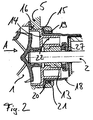
- the base plate 5 has a central, coaxial to the shaft 2 Bore in which the bearing bush 13 ( Figure 2) receiving bearing bracket 14 is held.
- the central one is formed by a sleeve molded onto the base plate 5 15 surround in which the bearing bracket 14 is inserted and is held by locking means 16.
- In the sleeve 15 is also a plastic can 18 held.
- the Holding of the can 18 happens in that the sleeve 15 has an inward collar 19 against the an outwardly directed collar 20 of the arrow A inserted can 18 by means of a sealing ring 21 comes to the plant.
- the collar 20 of the can 18 is from the bearing bracket 14 engaged in the sleeve 15 against the Sealing ring 21 pressurized.
- the bearing bracket 14 has one cylindrical wall 22 on which the containment shell 18 postponed and thus centered.
- the axial bearing of the Shaft 2 occurs through an axial bearing, the sliding ring 27 attacks on the end face of the bearing bush 13.
- FIG. 1 there is a plastic housing cover 23 placed on the all on the electrical side of the base plate 5 arranged components covers and thus the engine cover forms.
- the housing cover 23 lies on the outer surface of the Stator 10 receiving cylinder 9 and is together with the housing shell 4 screwed to the base plate 5.
- On its inner end face has a housing cover 23 Recording 24 in which the can 18 can be inserted.
- On the inside of the containment shell 18 is a sleeve 25 integrally formed, in which the second bearing bush 26 lies. Consequently the housing cover 23 takes over the sealing of the electric motor to the outside world and centers that of the Impeller facing away from the rotor. Will when shedding the electronics also insulates the contacts to the stator, no separate seal on the motor housing is necessary.
- the electronic module is first in the assembly sequence 11 attached and then the stator 10 mounted.
- the already assembled rotor assembly including the Split tops made of plastic is from the pump housing side inserted into the base plate 5.
- the seal between The O-ring takes over wet and dry space in a groove sits in the base plate 5.
- the can 18 is only slightly burdened.
- Reach for axial support Snap hook attached to the bearing bracket 14, in the Base plate 5. The snap hooks can be used with a tool loosened and the rotor assembly dismantled.
Landscapes
- Engineering & Computer Science (AREA)
- Mechanical Engineering (AREA)
- General Engineering & Computer Science (AREA)
- Power Engineering (AREA)
- Microelectronics & Electronic Packaging (AREA)
- Physics & Mathematics (AREA)
- Thermal Sciences (AREA)
- Structures Of Non-Positive Displacement Pumps (AREA)
Claims (16)
- Pompe centrifuge entraínée électriquement, en particulier pour la mise en oeuvre dans des circuits de chauffage et/ou de refroidissement, avec un carter de pompe (4) qui recouvre du côté frontal une chambre de roue mobile recevant une roue mobile, avec un stator (10) entouré par des bobinages et avec une plaque de montage (3) d'une seule pièce qui porte d'une part le carter de pompe (4) et d'autre part le stator (10) et qui présente des moyens pour la fixation de la pompe, la plaque de montage (3) d'une seule pièce présentant une plaque de base (5) alignée orthogonalement à l'arbre (2) de la roue mobile (1), qui forme une paroi de la chambre de roue mobile, et la plaque de montage présentant un logement (9) pour le centrage du stator (10), qui est conformé sur le côté de la plaque de base (5) écarté de la chambre de roue mobile.
- Pompe centrifuge selon la revendication 1,
caractérisée par le fait que le logement est formé par un cylindre (9) conformé sur la plaque de base (5) coaxialement à l'arbre (2) de la roue mobile, dans lequel le stator (10) peut être inséré, en particulier enfoncé. - Pompe centrifuge selon la revendication 2,
caractérisée par le fait que la plaque de montage (3) est emboutie ou moulée sous pression en métal, en particulier en tôle. - Pompe centrifuge selon l'une des revendications précédentes,
caractérisée par le fait que le logement forme la fixation pour le stator. - Pompe centrifuge selon l'une des revendications précédentes,
caractérisée par un module électronique (11) qui présente en particulier une électronique de commande avec des semi-conducteurs de puissance, le module électronique (11) étant maintenu en contact thermique sur le côté écarté de la roue mobile (1) de la plaque de base (5) formant un puits thermique. - Pompe centrifuge selon l'une des revendications précédentes,
caractérisée par le fait que la plaque de base (5) présente un alésage central aligné coaxialement à l'arbre de la roue mobile, dans lequel est maintenu un support de palier (14) recevant un palier (13). - Pompe centrifuge selon la revendication 6,
caractérisée par le fait que l'alésage central est entouré par un manchon (15) qui est conformé sur la plaque de base (5) et dans lequel le support de palier (14) est maintenu par des moyens d'encliquetage (16) et/ou enfoncé. - Pompe centrifuge selon l'une des revendications précédentes,
caractérisée par le fait qu'un pot d'entrefer (18), en particulier formé en matière synthétique, est maintenu dans le manchon (15). - Pompe centrifuge selon l'une des revendications précédentes,
caractérisée par le fait que le manchon (15) présente une collerette (19) dirigée vers l'intérieur contre laquelle vient en appui, en particulier au moyen d'une bague d'étanchéité (21), une collerette (20) dirigée vers l'extérieur du pot d'entrefer (18) introduit, le pot d'entrefer (18) étant soumis à une pression par le support de palier (14). - Pompe centrifuge selon l'une des revendications précédentes,
caractérisée par le fait qu'une paroi (22) cylindrique du support de palier centre le pot d'entrefer. - Pompe centrifuge selon l'une des revendications précédentes,
caractérisée par le fait qu'un couvercle de carter (23), en particulier formé en matière synthétique, peut être monté sur la plaque de base (5), lequel recouvre les composants disposés sur le côté électrique de la plaque de base (5). - Pompe centrifuge selon la revendication 11,
caractérisée par le fait que le couvercle de carter (23) est en appui sur la surface extérieure du cylindre (9) recevant le stator (10). - Pompe centrifuge selon l'une des revendications précédentes,
caractérisée par le fait que le carter de pompe présente une coque de carter (4), en particulier fabriquée en matière synthétique, qui est montée sur la plaque de base (5) et étanchée par l'intermédiaire d'une bague d'étanchéité (6). - Pompe centrifuge selon l'une des revendications précédentes,
caractérisée par le fait que l'entraínement a lieu au moyen d'un moteur à courant continu commuté électroniquement. - Pompe centrifuge selon l'une des revendications précédentes,
caractérisée par le fait que le connecteur de raccordement (12) pour l'alimentation électrique est monté sur le côté de la plaque de base (5) tourné vers la roue mobile (1). - Utilisation de la pompe centrifuge selon l'une des revendications précédentes pour le transport du liquide dans le circuit de refroidissement d'un véhicule automobile.
Applications Claiming Priority (2)
| Application Number | Priority Date | Filing Date | Title |
|---|---|---|---|
| DE19943862 | 1999-09-13 | ||
| DE19943862A DE19943862A1 (de) | 1999-09-13 | 1999-09-13 | Naßläuferpumpe mit Montageplatte |
Publications (3)
| Publication Number | Publication Date |
|---|---|
| EP1085213A2 EP1085213A2 (fr) | 2001-03-21 |
| EP1085213A3 EP1085213A3 (fr) | 2001-09-19 |
| EP1085213B1 true EP1085213B1 (fr) | 2004-11-17 |
Family
ID=7921887
Family Applications (1)
| Application Number | Title | Priority Date | Filing Date |
|---|---|---|---|
| EP00119886A Expired - Lifetime EP1085213B1 (fr) | 1999-09-13 | 2000-09-13 | Motopompe à rotor noyé et plaque de montage |
Country Status (2)
| Country | Link |
|---|---|
| EP (1) | EP1085213B1 (fr) |
| DE (2) | DE19943862A1 (fr) |
Cited By (2)
| Publication number | Priority date | Publication date | Assignee | Title |
|---|---|---|---|---|
| CN104411977A (zh) * | 2012-06-22 | 2015-03-11 | 威乐欧洲股份公司 | 具有滑环密封装置的马达离心泵 |
| US10935028B2 (en) | 2016-06-20 | 2021-03-02 | Pierburg Pump Technology Gmbh | Electric fluid pump for a motor vehicle |
Families Citing this family (17)
| Publication number | Priority date | Publication date | Assignee | Title |
|---|---|---|---|---|
| JP4034077B2 (ja) * | 2002-01-30 | 2008-01-16 | カルソニックカンセイ株式会社 | キャンドポンプ |
| DE10221843B4 (de) * | 2002-05-16 | 2004-12-30 | Minebea Co., Ltd. | Elektromotor zur Verwendung als Pumpenmotor und Pumpe |
| DE102004003400B4 (de) * | 2004-01-23 | 2012-08-23 | Ksb Aktiengesellschaft | Kreiselpumpenaggregat |
| GB2418072B (en) * | 2004-09-14 | 2008-05-07 | Dana Automotive Ltd | Pump assembly |
| DE102006027001A1 (de) * | 2006-06-08 | 2007-12-13 | Oase Gmbh | Wasserpumpe für insbesondere Teiche, Aquarien, Springbrunnen und dergleichen |
| DE102007033168A1 (de) * | 2007-07-17 | 2009-01-22 | Wilo Ag | Befestigung eines Radiallagers im Spalttopf |
| DE102008019608A1 (de) * | 2008-04-18 | 2009-10-22 | Continental Automotive Gmbh | Isolationsträger für einen Stator eines Elektromotors zum Antreiben von Flüssigkeitspumpen |
| PL2607710T3 (pl) * | 2011-12-23 | 2015-08-31 | Grundfos Holding As | Mokrobieżna pompa wirnikowa |
| DE102013004340A1 (de) * | 2013-03-14 | 2014-09-18 | Wilo Se | Gleitlagerbefestigung in einem Kreiselpumpenaggregat |
| DE102013020387A1 (de) * | 2013-12-10 | 2015-06-11 | Wilo Se | Nassläufermotorpumpe |
| DE202015105245U1 (de) * | 2015-10-05 | 2017-01-09 | Ebm-Papst St. Georgen Gmbh & Co. Kg | Elektromotor |
| CN106368954B (zh) * | 2016-11-29 | 2018-07-06 | 南通富莱克流体装备有限公司 | 浆料输送泵 |
| EP3382206B1 (fr) * | 2017-03-31 | 2020-12-16 | Grundfos Holding A/S | Ensemble de pompe |
| PL3382207T3 (pl) | 2017-03-31 | 2022-01-24 | Grundfos Holding A/S | Zespół pompy |
| US11705772B2 (en) | 2018-06-08 | 2023-07-18 | Pierburg Pump Technology Gmbh | Canned electric motor |
| CN114109853B (zh) * | 2020-08-27 | 2023-01-24 | 芜湖美的厨卫电器制造有限公司 | 水泵和具有其的热水器 |
| DE102021103610A1 (de) * | 2021-02-16 | 2022-08-18 | Ebm-Papst Mulfingen Gmbh & Co. Kg | Elektromotor, Elektronikmodul für einen Elektromotor, Verfahren zur Einstellung einer Referenzspannung und Verfahren zur Herstellung einer Vielzahl von Elektromotoren |
Family Cites Families (6)
| Publication number | Priority date | Publication date | Assignee | Title |
|---|---|---|---|---|
| US3433164A (en) * | 1967-03-03 | 1969-03-18 | Buffalo Forge Co | Motor-pump unit |
| DE1909878A1 (de) * | 1969-02-27 | 1970-09-17 | Hanning Elektro Werke | Heizungsumwaelzpumpe fuer kombinierten Schwerkraft- und Pumpenbetrieb |
| US4234293A (en) * | 1979-03-27 | 1980-11-18 | Dresser Industries, Inc. | Axial balancing system for motor driven pumps |
| US5494417A (en) * | 1994-08-03 | 1996-02-27 | Little Giant Pump Company | Shaft sealing and alignment assembly for a pump assembly |
| DE19527879A1 (de) * | 1995-07-29 | 1997-01-30 | Lutz Pumpen Gmbh & Co Kg | Elektromotor, insbesondere Antriebsmotor für eine Faß- oder Behälterpumpe |
| DE19545561A1 (de) * | 1995-12-07 | 1997-06-12 | Pierburg Ag | Pumpe-Motoreinheit |
-
1999
- 1999-09-13 DE DE19943862A patent/DE19943862A1/de not_active Withdrawn
-
2000
- 2000-09-13 EP EP00119886A patent/EP1085213B1/fr not_active Expired - Lifetime
- 2000-09-13 DE DE50008650T patent/DE50008650D1/de not_active Expired - Lifetime
Cited By (2)
| Publication number | Priority date | Publication date | Assignee | Title |
|---|---|---|---|---|
| CN104411977A (zh) * | 2012-06-22 | 2015-03-11 | 威乐欧洲股份公司 | 具有滑环密封装置的马达离心泵 |
| US10935028B2 (en) | 2016-06-20 | 2021-03-02 | Pierburg Pump Technology Gmbh | Electric fluid pump for a motor vehicle |
Also Published As
| Publication number | Publication date |
|---|---|
| EP1085213A2 (fr) | 2001-03-21 |
| EP1085213A3 (fr) | 2001-09-19 |
| DE50008650D1 (de) | 2004-12-23 |
| DE19943862A1 (de) | 2001-03-15 |
Similar Documents
| Publication | Publication Date | Title |
|---|---|---|
| EP1085213B1 (fr) | Motopompe à rotor noyé et plaque de montage | |
| DE102015114783B3 (de) | Elektrische Kühlmittelpumpe mit strömungsgekühlter Steuerschaltung | |
| DE102011001041B4 (de) | Magnetisch angetriebene Pumpenanordnung mit einer Mikropumpe mit Zwangsspuelung und Arbeitsverfahren | |
| DE102008064099B4 (de) | Kreiselpumpe mit einer feststehenden Achse | |
| US7045922B2 (en) | Permanent-magnet synchronous electric motor with isolated rotor for circulation pumps of heating and/or conditioning systems | |
| EP3411940B1 (fr) | Moteur électrique destiné à une pompe à fluide, famille de moteurs modulaire pour former des pompes à fluide différentes comportant plusieurs desdits moteurs électriques et procédé de fabrication | |
| DE19646617A1 (de) | Kühlmittelpumpe mit elektrisch kommutiertem Elektromotor | |
| EP1256722B1 (fr) | Pompe centrifugale | |
| EP1429443A1 (fr) | Moteur électrique à gaine avec une gaine servant de support aux enroulements | |
| DE102016202463A1 (de) | Elektronische Steuervorrichtung, Motorsteuervorrichtung und elektrische Fluidpumpe | |
| DE102018126775B4 (de) | Elektrische Wasserpumpe mit aktiver Kühlung | |
| EP3765712A1 (fr) | Système modulaire d'une structure de pompe axialement intégrée | |
| DE19943577A1 (de) | Pumpengehäuse mit integrierter Elektronik | |
| DE10103209A1 (de) | Motorgehäuse mit Spalttopf | |
| DE10045596B4 (de) | Pumpe mit einem elektronisch kommutierten Gleichstrommotor | |
| EP3940239B1 (fr) | Turbomachine avec canal de refroidissement | |
| EP1117169B1 (fr) | Refroidissement d'un module électronique par le couvercle du manchon d'entrefer | |
| DE4309382A1 (de) | Elektronisch kommutierter Elektromotor | |
| EP4229300B1 (fr) | Unité d'accouplement à effet de séparation thermique | |
| DE102020106796A1 (de) | Pumpeneinsatz und Pumpenanordnung mit einem solchen Pumpeneinsatz | |
| EP1343645B1 (fr) | Appareil de chauffage automobile comportant une pompe de recirculation de caloporteur integree | |
| EP1691468B1 (fr) | Unité de pompage | |
| DE10133767A1 (de) | Kommutatormotor mit einem zylinderförmigen Motorgehäuse | |
| WO2013037449A2 (fr) | Groupe électro-pompe | |
| DE102004047637B4 (de) | Elektrisch betriebene Pumpe mit Außenrotor |
Legal Events
| Date | Code | Title | Description |
|---|---|---|---|
| PUAI | Public reference made under article 153(3) epc to a published international application that has entered the european phase |
Free format text: ORIGINAL CODE: 0009012 |
|
| AK | Designated contracting states |
Kind code of ref document: A2 Designated state(s): AT BE CH CY DE DK ES FI FR GB GR IE IT LI LU MC NL PT SE Kind code of ref document: A2 Designated state(s): DE FR GB IT |
|
| AX | Request for extension of the european patent |
Free format text: AL;LT;LV;MK;RO;SI |
|
| PUAL | Search report despatched |
Free format text: ORIGINAL CODE: 0009013 |
|
| AK | Designated contracting states |
Kind code of ref document: A3 Designated state(s): AT BE CH CY DE DK ES FI FR GB GR IE IT LI LU MC NL PT SE |
|
| AX | Request for extension of the european patent |
Free format text: AL;LT;LV;MK;RO;SI |
|
| 17P | Request for examination filed |
Effective date: 20010823 |
|
| AKX | Designation fees paid |
Free format text: DE FR GB IT |
|
| GRAP | Despatch of communication of intention to grant a patent |
Free format text: ORIGINAL CODE: EPIDOSNIGR1 |
|
| GRAS | Grant fee paid |
Free format text: ORIGINAL CODE: EPIDOSNIGR3 |
|
| RAP1 | Party data changed (applicant data changed or rights of an application transferred) |
Owner name: WILO AG |
|
| GRAA | (expected) grant |
Free format text: ORIGINAL CODE: 0009210 |
|
| AK | Designated contracting states |
Kind code of ref document: B1 Designated state(s): DE FR GB IT |
|
| REG | Reference to a national code |
Ref country code: GB Ref legal event code: FG4D Free format text: NOT ENGLISH |
|
| REF | Corresponds to: |
Ref document number: 50008650 Country of ref document: DE Date of ref document: 20041223 Kind code of ref document: P |
|
| GBT | Gb: translation of ep patent filed (gb section 77(6)(a)/1977) |
Effective date: 20050111 |
|
| PLBE | No opposition filed within time limit |
Free format text: ORIGINAL CODE: 0009261 |
|
| STAA | Information on the status of an ep patent application or granted ep patent |
Free format text: STATUS: NO OPPOSITION FILED WITHIN TIME LIMIT |
|
| 26N | No opposition filed |
Effective date: 20050818 |
|
| ET | Fr: translation filed | ||
| PGFP | Annual fee paid to national office [announced via postgrant information from national office to epo] |
Ref country code: GB Payment date: 20130911 Year of fee payment: 14 |
|
| REG | Reference to a national code |
Ref country code: DE Ref legal event code: R082 Ref document number: 50008650 Country of ref document: DE Representative=s name: PATENTANWAELTE TER SMITTEN EBERLEIN RUETTEN PA, DE |
|
| GBPC | Gb: european patent ceased through non-payment of renewal fee |
Effective date: 20140913 |
|
| REG | Reference to a national code |
Ref country code: DE Ref legal event code: R081 Ref document number: 50008650 Country of ref document: DE Owner name: PIERBURG PUMP TECHNOLOGY GMBH, DE Free format text: FORMER OWNER: WILO AG, 44263 DORTMUND, DE Effective date: 20150513 Ref country code: DE Ref legal event code: R082 Ref document number: 50008650 Country of ref document: DE Representative=s name: PATENTANWAELTE TER SMITTEN EBERLEIN RUETTEN PA, DE Effective date: 20150513 Ref country code: DE Ref legal event code: R082 Ref document number: 50008650 Country of ref document: DE Representative=s name: PATENTANWAELTE TER SMITTEN EBERLEIN-VAN HOOF R, DE Effective date: 20150513 |
|
| PG25 | Lapsed in a contracting state [announced via postgrant information from national office to epo] |
Ref country code: GB Free format text: LAPSE BECAUSE OF NON-PAYMENT OF DUE FEES Effective date: 20140913 |
|
| REG | Reference to a national code |
Ref country code: FR Ref legal event code: PLFP Year of fee payment: 16 |
|
| REG | Reference to a national code |
Ref country code: FR Ref legal event code: TP Owner name: PIERBURG PUMP TECHNOLOGY GMBH, DE Effective date: 20151118 Ref country code: FR Ref legal event code: CJ Effective date: 20151118 Ref country code: FR Ref legal event code: CD Owner name: PIERBURG PUMP TECHNOLOGY GMBH, DE Effective date: 20151118 |
|
| REG | Reference to a national code |
Ref country code: FR Ref legal event code: PLFP Year of fee payment: 17 |
|
| REG | Reference to a national code |
Ref country code: FR Ref legal event code: PLFP Year of fee payment: 18 |
|
| REG | Reference to a national code |
Ref country code: FR Ref legal event code: PLFP Year of fee payment: 19 |
|
| PGFP | Annual fee paid to national office [announced via postgrant information from national office to epo] |
Ref country code: IT Payment date: 20180921 Year of fee payment: 19 Ref country code: FR Payment date: 20180921 Year of fee payment: 19 Ref country code: DE Payment date: 20180924 Year of fee payment: 19 |
|
| REG | Reference to a national code |
Ref country code: DE Ref legal event code: R082 Ref document number: 50008650 Country of ref document: DE Representative=s name: TERPATENT PATENTANWAELTE TER SMITTEN EBERLEIN-, DE |
|
| REG | Reference to a national code |
Ref country code: DE Ref legal event code: R119 Ref document number: 50008650 Country of ref document: DE |
|
| PG25 | Lapsed in a contracting state [announced via postgrant information from national office to epo] |
Ref country code: DE Free format text: LAPSE BECAUSE OF NON-PAYMENT OF DUE FEES Effective date: 20200401 |
|
| PG25 | Lapsed in a contracting state [announced via postgrant information from national office to epo] |
Ref country code: IT Free format text: LAPSE BECAUSE OF NON-PAYMENT OF DUE FEES Effective date: 20190913 |
|
| PG25 | Lapsed in a contracting state [announced via postgrant information from national office to epo] |
Ref country code: FR Free format text: LAPSE BECAUSE OF NON-PAYMENT OF DUE FEES Effective date: 20190930 |