EP1085247A2 - Joints d'étanchéité d'un raccord flexible à faibles pertes pour conduits de gaz - Google Patents
Joints d'étanchéité d'un raccord flexible à faibles pertes pour conduits de gaz Download PDFInfo
- Publication number
- EP1085247A2 EP1085247A2 EP00116380A EP00116380A EP1085247A2 EP 1085247 A2 EP1085247 A2 EP 1085247A2 EP 00116380 A EP00116380 A EP 00116380A EP 00116380 A EP00116380 A EP 00116380A EP 1085247 A2 EP1085247 A2 EP 1085247A2
- Authority
- EP
- European Patent Office
- Prior art keywords
- ring
- annularly extending
- base portion
- radially
- seal ring
- Prior art date
- Legal status (The legal status is an assumption and is not a legal conclusion. Google has not performed a legal analysis and makes no representation as to the accuracy of the status listed.)
- Granted
Links
Images

Classifications
-
- F—MECHANICAL ENGINEERING; LIGHTING; HEATING; WEAPONS; BLASTING
- F16—ENGINEERING ELEMENTS AND UNITS; GENERAL MEASURES FOR PRODUCING AND MAINTAINING EFFECTIVE FUNCTIONING OF MACHINES OR INSTALLATIONS; THERMAL INSULATION IN GENERAL
- F16L—PIPES; JOINTS OR FITTINGS FOR PIPES; SUPPORTS FOR PIPES, CABLES OR PROTECTIVE TUBING; MEANS FOR THERMAL INSULATION IN GENERAL
- F16L27/00—Adjustable joints; Joints allowing movement
- F16L27/02—Universal joints, i.e. with mechanical connection allowing angular movement or adjustment of the axes of the parts in any direction
- F16L27/026—Universal and axially displaceable joints
-
- F—MECHANICAL ENGINEERING; LIGHTING; HEATING; WEAPONS; BLASTING
- F16—ENGINEERING ELEMENTS AND UNITS; GENERAL MEASURES FOR PRODUCING AND MAINTAINING EFFECTIVE FUNCTIONING OF MACHINES OR INSTALLATIONS; THERMAL INSULATION IN GENERAL
- F16J—PISTONS; CYLINDERS; SEALINGS
- F16J3/00—Diaphragms; Bellows; Bellows pistons
- F16J3/04—Bellows
- F16J3/047—Metallic bellows
-
- F—MECHANICAL ENGINEERING; LIGHTING; HEATING; WEAPONS; BLASTING
- F16—ENGINEERING ELEMENTS AND UNITS; GENERAL MEASURES FOR PRODUCING AND MAINTAINING EFFECTIVE FUNCTIONING OF MACHINES OR INSTALLATIONS; THERMAL INSULATION IN GENERAL
- F16L—PIPES; JOINTS OR FITTINGS FOR PIPES; SUPPORTS FOR PIPES, CABLES OR PROTECTIVE TUBING; MEANS FOR THERMAL INSULATION IN GENERAL
- F16L27/00—Adjustable joints; Joints allowing movement
- F16L27/02—Universal joints, i.e. with mechanical connection allowing angular movement or adjustment of the axes of the parts in any direction
- F16L27/023—Universal and rotating joints
-
- F—MECHANICAL ENGINEERING; LIGHTING; HEATING; WEAPONS; BLASTING
- F16—ENGINEERING ELEMENTS AND UNITS; GENERAL MEASURES FOR PRODUCING AND MAINTAINING EFFECTIVE FUNCTIONING OF MACHINES OR INSTALLATIONS; THERMAL INSULATION IN GENERAL
- F16L—PIPES; JOINTS OR FITTINGS FOR PIPES; SUPPORTS FOR PIPES, CABLES OR PROTECTIVE TUBING; MEANS FOR THERMAL INSULATION IN GENERAL
- F16L27/00—Adjustable joints; Joints allowing movement
- F16L27/10—Adjustable joints; Joints allowing movement comprising a flexible connection only
- F16L27/107—Adjustable joints; Joints allowing movement comprising a flexible connection only the ends of the pipe being interconnected by a flexible sleeve
-
- Y—GENERAL TAGGING OF NEW TECHNOLOGICAL DEVELOPMENTS; GENERAL TAGGING OF CROSS-SECTIONAL TECHNOLOGIES SPANNING OVER SEVERAL SECTIONS OF THE IPC; TECHNICAL SUBJECTS COVERED BY FORMER USPC CROSS-REFERENCE ART COLLECTIONS [XRACs] AND DIGESTS
- Y10—TECHNICAL SUBJECTS COVERED BY FORMER USPC
- Y10S—TECHNICAL SUBJECTS COVERED BY FORMER USPC CROSS-REFERENCE ART COLLECTIONS [XRACs] AND DIGESTS
- Y10S285/00—Pipe joints or couplings
- Y10S285/906—Equivalents
-
- Y—GENERAL TAGGING OF NEW TECHNOLOGICAL DEVELOPMENTS; GENERAL TAGGING OF CROSS-SECTIONAL TECHNOLOGIES SPANNING OVER SEVERAL SECTIONS OF THE IPC; TECHNICAL SUBJECTS COVERED BY FORMER USPC CROSS-REFERENCE ART COLLECTIONS [XRACs] AND DIGESTS
- Y10—TECHNICAL SUBJECTS COVERED BY FORMER USPC
- Y10S—TECHNICAL SUBJECTS COVERED BY FORMER USPC CROSS-REFERENCE ART COLLECTIONS [XRACs] AND DIGESTS
- Y10S285/00—Pipe joints or couplings
- Y10S285/91—Gaskets
Definitions
- This invention relates generally to sealing rings and, more specifically, to sealing rings used in the flexible joinder of end portions of two opposed gas conduits for permitting gas flow therebetween during angular misalignment movement or offset, axial translation, axial rotation, and vibration of the conduits with a minimum of gas leakage.
- the sealing ring assemblies used in the ring housings of flexible coupling sleeves or in ring channels disposed between opposed, concentrically overlapping end portions of gas conduits of different diameters typically operate at air pressures from 40 to 70 psig at temperatures from ambient up to 350 to 500°F.
- Silicone seal rings have typically been used for this purpose in the prior art. While such prior art seal rings have good flexibility when originally installed and operated at low temperatures of from ambient up to about 200°F, they have a tendency to crack, become cracked and brittle and developed burned spots or areas when subjected to the typical high operating temperature range encountered in gas ducting or conduct systems of commercial jet engines.
- a sealing ring which can be made of such Teflon and plastic material which has none of the problems encountered with silicone rings in the 350 to 500° F operating temperature range, yet is sufficiently flexible at all temperatures from ambient up to and through this typical high temperature range to provide excellent sealing characteristics for adjoined gas conduits which are subject to various vibratory and other movements relative to one another.
- a seal ring which includes an annulus of flexible, resilient material having a generally U-shaped radial cross-section.
- a pair of legs of the cross-section form axially spaced apart, annularly extending side walls and, together with an annularly extending base portion of the cross-section, forms an endless, annularly extending central groove.
- a pair of annularly extending axially spaced apart slots are formed in the base portion next to opposing surfaces of the side walls, which slots open into the groove.
- a spring member is disposed in the groove for urging an edge of the annulus which faces in a radial direction away from the groove to seal against an opposing, conforming, annually extending surface against which the edge is operatively placed.
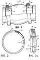
- a flexible coupling generally designated 10 ( FIG. 1 only), including a conventional hollow, open ended sleeve 12 and a novel pair of seal rings, generally designated 14 , 16 .
- the sleeve 12 fits on and around opposed, spaced apart end portions of a pair of cylindrically shaped gas or air conduits 18 , 20 .
- the conduits 18 , 20 are open on their opposing ends 22 and 24 for the flow of gas or air, under pressure, therebetween through the sleeve 12 .
- the conduits, 18 , 20 are shown axially misalign relative to one another or vertically offset as viewed.
- This may be considered either a permanent condition, as where the conduits 18 , 20 are permanently slightly misaligned, or a transient condition due to vibration or thermal expansion of the two conduits, as can occur, for example, under certain operating conditions in similarly coupled air conduits in commercial air craft.
- the novel seal rings 14 , 16 are disposed in a pair of annularly extending, three sided ring housings 26 , 28 , respectively, formed on and around opposite open ends of the sleeve. Since the rings 14 , 16 are identical, only one of such rings need be fully shown.
- the rings 14 , 16 are preferably constructed of a flexible, resilient Teflon or plastic and each includes an annularly extending base portion 30 and a pair of axially spaced apart side walls 32 , 34 which are integrally joined on radially inner end portions of opposing sides thereof to opposite sides of the base portion 30 .
- the radially inner edges of the side walls 32 , 34 and the radially inner facing surface of the base portion 30 together, define a radially interior, circular bore 36 of each of the rings 14 , 16 which is adapted to fit snugly on and around the cylindrically shaped outer surface of the conduits 18 , 20 , respectively.
- a pair of axially spaced apart, annularly extending, radially outwardly opening slots 38 , 40 are formed in radially outer surface portions of the base portion 30 next to opposing sides of the side walls 32 and 34 .
- the slots 38 , 40 give added flexibility to the side walls 32 , 34 thus permitting them to resiliently deform to provide an effective gas seal against the interior sidewalls of the ring housings 26 , 28 upon misaligning movement, rotation, translation, vibration or thermal expansion of the conduits 18 , 20 relative to one another.
- Such resilient deformation of the ring side walls 32 , 34 is illustrated in FIG. 4 at 32' and 34' .
- the rings 14 , 16 are split seal rings containing a lap joint, as at 41 in FIGS. 2 and 2 a , to permit them being placed in a compression or contraction mode on and around the conduits 18 , 20 as later more fully explained.
- the seal rings 14 , 16 may be uncut when adapted for use in a contracting mode as in the present example, although they must be split so as to contain a lap joint when adapted for use in an expanding mode.
- ring side walls 32 and 34 are joined along radially inner portions thereof to radially inner side portions of the base portion 30 , radially outer end portions of the side walls 32 , 34 project radially outwardly beyond an outer peripheral edge 42 of the base portion 30 to form a three sided central groove 44 (See FIGS. 3-4 ) in which is disposed a spring member such as a coiled, annularly extending garter spring 46 .
- the spring 46 provides a compression force against the base portion 30 to force the ring bore 36 of each of the rings 14 , 16 tightly against the outer surface of the corresponding conduit 18 , 20 .
- the rings 14 , 16 of FIGS. 1-4 thus operate in a contracting or compression mode.
- a spring member such as a metal split ring 47 ( FIG. 8 ) containing a standard butt joint 49 operating in compression, can be substituted in and around the groove 44 in place of the garter spring 46 to compress the rings 14 , 16 on their corresponding conduits.
- the ring 47 need not be a split ring but can be an uncut ring if preferred.
- a suitable Teflon for constructing the rings 14 , 16 includes, for example, that sold by DSM Engineering Plastic Products, Inc., 1911 East 29 th Avenue, North Kansas City, MO. 64116 under the trademark, Fluorosint 207 or Fluorosint 590.
- An optional feature of the rings 14 , 16 of FIGS. 1-4 is yet a third annually extending slot 51 formed in the base portion 30 which opens inwardly around the bore 36 against an outer surface of one of the conduits 18 , 20 .
- the slot 51 is positioned at the axial center of each of the rings 14 , 16 and its height, as measured from the bore 36 radically outwardly, should be slightly above the base of the other two slots 38 , 40 , as viewed, to give even greater flexibility to the rings 14 , 16 than is available where the rings have only the slots 38 , 40 without the third slot 51 .
- Two axially spaced apart slots such as the slot 51 could also be formed in the base portion 30 so as to open inwardly on and along the bore 36 to produce additional flexibility in the rings 14 , 16 if desired.
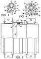
- FIGS. 5-7 another important embodiment of my invention is shown wherein concentrically interposed or overlapping end portions of two opposed and open ended cylindrical gas or air conduits 50 , 52 of different diameters are sealed between one another in an effectively gas tight manner by a pair of novel split seal rings 54 , 56 .
- the rings 54 , 56 are identical and each includes the same important features as the rings 14 , 16 of the previous example, including the lap joints as at 41 in FIGS. 2-2 a , except that, in the present example, the rings operate in an expansion mode rather than a compression or contraction mode.
- Each of the rings 54 , 56 is partially disposed in an annularly extending, endless, radially outwardly opening channel 58 attached to and around an exterior surface of the conduit 52 immediately adjacent an open end 60 thereof.
- each of the rings 54 , 56 include an annularly extending base portion 62 , and a pair of annularly extending, axially spaced apart side walls 64 , 66 attached on radially outer end portions to opposite sides of the base portion.
- a pair of annularly extending, spaced apart slots 68 , 70 are formed in radially inward surface portions of the base portion 62 immediately next to opposing sides of the side walls 64 , 66 so as to open radially inwardly.
- Radially inward end portions of the side walls 64 , 66 project radially inwardly beyond a radially inwardly facing surface 72 of the base portion 62 to form a radially inwardly opening central groove 73 in which an expansion spring member, such as, for example, a Marcel spring 74 is disposed.
- an expansion spring member such as, for example, a Marcel spring 74
- a conventional, radially outwardly expanding split ring such as at 47 in FIG. 8 and having a butt joint 49 can be inserted in the groove 73 in place of the Marcel spring 74 .
- the spring 74 or the expansion ring causes a radially outwardly facing surface 76 of each of the rings 54 , 56 , to bear tightly against an interior surface 78 of the conduit 50 (See also FIG. 5 ).
- a contracting spring ring, such as at 47 for use with the seal rings 14 , 16 can be of either a split or uncut type
- an expansion type spring ring, such as at 47 for use with expansion type seal rings 54 , 56 must be of a radically butt cut type.
- the rings 54 , 56 should be constructed of a flexible, resilient material such as plastic or Teflon.
- the slots 68 , 70 permit the side walls 64 , 66 to have increased flexibility so as to maintain an effectively gas tight seal between the conduits 50 , 52 with angular or axial misalignment movement, translational movement or vibratory movement thereof.
- expansion type seal rings such as used in the example of FIGS. 5-7 can also be used to seal the sleeve to the conduits.
- a seal ring assembly generally designated 80 , a different one of which can be used in each of the ring housings 26 and 28 of the sleeve 12 of the coupling shown in FIG. 1 in place of the rings 14 and 16 of the first example of the invention.
- Only a radially cross-sectioned portion of the ring assembly 80 is shown in FIG. 9 so as to be generic in terms of whether the subject ring assembly is one of the compression type, as in the case of the FIGS. 1-4 example, or is one of the expansion type, as is the case with the FIGS. 5-7 example. It may be equally well adapted for operation in either a compression mode or an expansion mode as desired.
- the assembly 80 comprises an annularly extending ring or annulus 82 and a pair of conventional metal garter springs 84 and 86 .
- the ring 82 When adapted for operation in a compression mode, the ring 82 may either be a split ring, preferably having a lap joint, such as shown at 41 in FIG. 2 a , or it may be uncut and solid throughout its periphery. However, when adapted for operation in an expansion mode, the ring 82 should be of the split ring type such as shown in FIG. 2 a .
- the ring 82 should also be made of a suitable Teflon or plastic, such as the Fluorosint 207 or Fluorosint 590 mentioned in the previous examples for high temperature applications in the 350°F - 500°F range as encountered, for example, in commercial aircraft engine air conduit applications.
- the ring 82 includes an annularly extending base or base portion 88 and a pair of axially spaced apart, annularly extending sidewalls 90 and 92 attached on corresponding radial end portions to opposite sides of the base 88 .
- An annularly extending first surface 94 of the base 88 which is a conduit bearing surface of the ring 82 , faces in a first radial direction for fitting in an effectively gas sealing manner against an opposing conforming surface of a gas conduit, not shown.
- An annularly extending second surface 96 a, b lying between the sidewalls 90 and 92 , faces in a second radial direction opposite the first radial direction.
- the second surface 96 a, b and opposing surfaces of the sidewalls 90 and 92 which project radially beyond the base 88 define an annularly extending groove 98 .
- a pair of annularly extending, axially spaced apart slots 100 and 102 are formed in a surface portion of the base 88 next to the opposing surfaces of the sidewalls 90 and 92 so as to open onto the second surface 96 a, b into the groove 98 .
- the second surface 96 a, b is crowned, as at 104 , on an annularly extending, axial centerline of the ring 82 and contains a pair of oppositely tapered, annularly extending surfaces 96 a and 96 b .
- the tapered surfaces 96 a and 96 b extend diagonally outwardly in opposite axial directions from the crown 104 to form a pair of cone shaped surfaces which are each inclined toward an imaginary circular cylindrical, axially directed projection of the first surface 94 .
- the cone shaped or tapered surfaces 96 a and 96 b are on opposite angles relative to one another which are equal to an angle ⁇ as shown in FIG. 4 and which are inclined toward the imaginary projection of the surface 94 , the angle ⁇ being within a range of from three degrees to about thirty degrees, inclusive.
- the garter springs 84 and 86 are disposed next to one another in the groove 98 such that each of the springs bears upon a different one of the tapered surfaces 96 a and 96 b .
- Such an arrangement produces a radially directed bearing force component 106 from each of the springs upon the first surface 94 which combined to cause the surface 94 to form an effectively gas tight seal against the gas conduit in combination with a gas pressure differential which will also exist across the surfaces 94 and 96 a, b under operating conditions.
- the springs 84 and 86 bear upon tapered surfaces 96 a and 96 b respectively, they each provide an opposite, axially outwardly directed force component 108 against a nearest one of the sidewalls 90 and 92 to form an effectively gas tight seal of the sidewalls against opposing annularly extending surfaces of the ring housing in which they are disposed, such as the ring housings 26 and 28 of FIG. 1 for example. Because the angle ⁇ of each of the tapered surfaces 96 a and 96 b will be within the aforementioned range, the axially directed mechanical force component 108 of each of the springs 84 and 86 will fall within a range of from about one to ten percent of the radially directed mechanical force component 106 .
- Typical commercial aircraft operating gas pressures of from about 45 to 70 psig will produce gas pressure differentials radially across the base 88 and axially across each of the sidewalls 90 and 92 which will add to the mechanical force components 106 and 108 , respectively, to produce an effective gas tight seal of the ring 82 in and against its housing or channel.
Landscapes
- Engineering & Computer Science (AREA)
- General Engineering & Computer Science (AREA)
- Mechanical Engineering (AREA)
- Joints Allowing Movement (AREA)
- Gasket Seals (AREA)
- Package Frames And Binding Bands (AREA)
Applications Claiming Priority (2)
| Application Number | Priority Date | Filing Date | Title |
|---|---|---|---|
| US09/396,920 US6179339B1 (en) | 1999-09-15 | 1999-09-15 | Seal rings for low loss flexible coupling of gas conduits |
| US396920 | 1999-09-15 |
Publications (3)
| Publication Number | Publication Date |
|---|---|
| EP1085247A2 true EP1085247A2 (fr) | 2001-03-21 |
| EP1085247A3 EP1085247A3 (fr) | 2002-07-31 |
| EP1085247B1 EP1085247B1 (fr) | 2005-03-23 |
Family
ID=23569129
Family Applications (1)
| Application Number | Title | Priority Date | Filing Date |
|---|---|---|---|
| EP00116380A Expired - Lifetime EP1085247B1 (fr) | 1999-09-15 | 2000-07-28 | Joints d'étanchéité d'un raccord flexible à faibles pertes pour conduits de gaz |
Country Status (4)
| Country | Link |
|---|---|
| US (1) | US6179339B1 (fr) |
| EP (1) | EP1085247B1 (fr) |
| AT (1) | ATE291714T1 (fr) |
| DE (1) | DE60018864T2 (fr) |
Cited By (2)
| Publication number | Priority date | Publication date | Assignee | Title |
|---|---|---|---|---|
| BE1017253A3 (fr) * | 2005-08-26 | 2008-05-06 | Gen Electric | Raccord deformable pour modules de crepines de systeme de refroidissement de secours pour reacteur nucleaire. |
| EP2570709A1 (fr) * | 2011-09-15 | 2013-03-20 | Airbus Operations GmbH | Couplage mobile pour un pipeline, agencement de réservoir et aéronef ou engin spatial |
Families Citing this family (11)
| Publication number | Priority date | Publication date | Assignee | Title |
|---|---|---|---|---|
| US6709024B1 (en) | 2000-09-27 | 2004-03-23 | General Electric Company | Method and apparatus for assembling couplings for transferring fluids |
| US6905144B2 (en) * | 2003-07-02 | 2005-06-14 | Delaware Capital Formation | Spring-loaded ‘L’-shaped seal ring |
| US7452005B2 (en) * | 2005-08-24 | 2008-11-18 | Rcf Technologies, Inc. | Duct sealing apparatus |
| DE102005052517B4 (de) * | 2005-11-03 | 2010-01-21 | Schwing Gmbh | Rohrleitungskupplung mit einem Dichtungsring und Rohrleitungssystem für die Förderung von Dickstoffen |
| US20090242043A1 (en) * | 2008-03-31 | 2009-10-01 | Gm Global Technology Operations, Inc. | Hydrogen supply pressure regulator |
| US7883094B2 (en) * | 2008-08-19 | 2011-02-08 | Delaware Capital Formation, Inc. | Offset stacked sealing system |
| US8186692B2 (en) | 2009-03-17 | 2012-05-29 | Pratt & Whitney Canada Corp. | Split ring seal with spring element |
| EP2791458A4 (fr) * | 2011-12-14 | 2016-06-01 | Utex Ind Inc | Ensemble siège extensible pour isolation de zones de fracture dans un puits |
| US10287990B2 (en) * | 2014-08-08 | 2019-05-14 | Rohr, Inc. | Bleed system bolted duct with recessed seals |
| US12158226B2 (en) | 2020-05-15 | 2024-12-03 | Roller Bearing Company Of America, Inc. | Flexible alignment sealing coupling |
| WO2025171363A1 (fr) * | 2024-02-08 | 2025-08-14 | Kinetic Pressure Control, Ltd. | Ensemble joint d'étanchéité en plusieurs pièces |
Family Cites Families (20)
| Publication number | Priority date | Publication date | Assignee | Title |
|---|---|---|---|---|
| US1045460A (en) | 1912-08-19 | 1912-11-26 | John C Tudor | Rod-packing. |
| US2070637A (en) | 1935-11-20 | 1937-02-16 | Chicago Rawhide Mfg Co | Oil seal |
| US2212335A (en) | 1936-03-27 | 1940-08-20 | Company Fidelity Union Trust | Packing ring |
| US2434484A (en) | 1945-02-09 | 1948-01-13 | Garlock Packing Co | Oil seal |
| US2438794A (en) | 1945-09-01 | 1948-03-30 | Waring Arthur | Packing or sealing ring |
| NL64639C (fr) | 1945-10-29 | |||
| US2826437A (en) | 1954-11-30 | 1958-03-11 | Lockheed Aircraft Corp | Flexible coupling for rigid beaded tubes |
| US2937037A (en) | 1956-08-27 | 1960-05-17 | Aeroquip Corp | Flexible fluid line coupling with spring loaded seal rings |
| US2888281A (en) | 1957-01-23 | 1959-05-26 | Chicago Rawhide Mfg Co | Self-compensating seal |
| US3405957A (en) | 1967-04-03 | 1968-10-15 | Richard O. Chakroff | Flexible tube coupling |
| US3680874A (en) * | 1970-08-24 | 1972-08-01 | Federal Mogul Corp | Flexible pneumatic duct connectors assembled with internal seals |
| US3827703A (en) | 1971-07-23 | 1974-08-06 | Chicago Rawhide Mfg Co | Radial shaft seal with positive garter spring retention |
| US3787079A (en) | 1972-04-13 | 1974-01-22 | Gen Connector Corp | Sealing connection for conduit couplings |
| FR2489463B1 (fr) * | 1980-08-26 | 1987-05-15 | Gen Connector Corp | Joint annulaire d'etancheite, procede de construction de ce joint, moules et dispositif pour la mise en oeuvre de ce procede, application de ce joint pour la connexion de deux gaines |
| US4453723A (en) * | 1980-12-02 | 1984-06-12 | General Connectors Corp. | Seal |
| US4813713A (en) | 1984-11-19 | 1989-03-21 | Lockheed Corporation | Flexible coupling for fluid ducts |
| US4830344A (en) | 1988-04-25 | 1989-05-16 | Peter J. Balsells | Canted-coil spring with turn angle and seal |
| US4974821A (en) * | 1988-04-25 | 1990-12-04 | Peter J. Balsells | Canted-coil spring with major axis radial loading |
| US5106129A (en) * | 1990-10-09 | 1992-04-21 | Delaware Capital Formation, Inc. | Flexible coupling for transferring a fluid between two fluid conduits |
| JP3284906B2 (ja) * | 1996-02-21 | 2002-05-27 | ダイキン工業株式会社 | 極低温冷凍機 |
-
1999
- 1999-09-15 US US09/396,920 patent/US6179339B1/en not_active Expired - Lifetime
-
2000
- 2000-07-28 DE DE60018864T patent/DE60018864T2/de not_active Expired - Lifetime
- 2000-07-28 EP EP00116380A patent/EP1085247B1/fr not_active Expired - Lifetime
- 2000-07-28 AT AT00116380T patent/ATE291714T1/de not_active IP Right Cessation
Cited By (3)
| Publication number | Priority date | Publication date | Assignee | Title |
|---|---|---|---|---|
| BE1017253A3 (fr) * | 2005-08-26 | 2008-05-06 | Gen Electric | Raccord deformable pour modules de crepines de systeme de refroidissement de secours pour reacteur nucleaire. |
| EP2570709A1 (fr) * | 2011-09-15 | 2013-03-20 | Airbus Operations GmbH | Couplage mobile pour un pipeline, agencement de réservoir et aéronef ou engin spatial |
| US9599263B2 (en) | 2011-09-15 | 2017-03-21 | Airbus Operations Gmbh | Movable coupling for a pipeline, tank arrangement, and aircraft or spacecraft |
Also Published As
| Publication number | Publication date |
|---|---|
| US6179339B1 (en) | 2001-01-30 |
| DE60018864D1 (de) | 2005-04-28 |
| DE60018864T2 (de) | 2006-01-12 |
| ATE291714T1 (de) | 2005-04-15 |
| EP1085247A3 (fr) | 2002-07-31 |
| EP1085247B1 (fr) | 2005-03-23 |
Similar Documents
| Publication | Publication Date | Title |
|---|---|---|
| US6179339B1 (en) | Seal rings for low loss flexible coupling of gas conduits | |
| US5470114A (en) | Coupling assembly | |
| US5716052A (en) | Pressure-energized sealing rings | |
| US7883094B2 (en) | Offset stacked sealing system | |
| US4893847A (en) | Bearing seal for universal ball joint | |
| RU2224155C2 (ru) | Вложенное уплотнение моста | |
| US5149109A (en) | Interlocking segmented seal | |
| US3664691A (en) | Pipe joints | |
| US3724878A (en) | Flexible connector | |
| US5649713A (en) | Gasket for hub and spigot pipe joints | |
| US5799954A (en) | Coaxial sealing ring | |
| US5158305A (en) | Pressure-energized two-element seal | |
| US3695639A (en) | Connector | |
| US4589666A (en) | Slip joint assembly for a split ring seal | |
| EP0770810B1 (fr) | Joint de dilatation | |
| US6709024B1 (en) | Method and apparatus for assembling couplings for transferring fluids | |
| JP3467500B2 (ja) | 配管用継手 | |
| EP0226845B1 (fr) | Garniture d'étanchéité en une seule pièce | |
| EP0084538B1 (fr) | Assemblage d'etancheite dans un couplage de fluide | |
| US5074697A (en) | Releasable connector for interconnecting two parts subjected to high stresses | |
| US4832353A (en) | Ring seals | |
| US5098133A (en) | Tube coupling with swivelable piston | |
| US4147383A (en) | Pipe coupling | |
| US4072329A (en) | Flexible fluid connecting device | |
| US2758851A (en) | Packed ball and socket pipe joint |
Legal Events
| Date | Code | Title | Description |
|---|---|---|---|
| PUAI | Public reference made under article 153(3) epc to a published international application that has entered the european phase |
Free format text: ORIGINAL CODE: 0009012 |
|
| AK | Designated contracting states |
Kind code of ref document: A2 Designated state(s): AT BE CH CY DE DK ES FI FR GB GR IE IT LI LU MC NL PT SE |
|
| AX | Request for extension of the european patent |
Free format text: AL;LT;LV;MK;RO;SI |
|
| PUAL | Search report despatched |
Free format text: ORIGINAL CODE: 0009013 |
|
| RIC1 | Information provided on ipc code assigned before grant |
Free format text: 7F 16L 27/107 A, 7F 16J 15/32 B, 7F 16J 3/04 B |
|
| AK | Designated contracting states |
Kind code of ref document: A3 Designated state(s): AT BE CH CY DE DK ES FI FR GB GR IE IT LI LU MC NL PT SE |
|
| AX | Request for extension of the european patent |
Free format text: AL;LT;LV;MK;RO;SI |
|
| 17P | Request for examination filed |
Effective date: 20020726 |
|
| AKX | Designation fees paid |
Designated state(s): AT BE CH CY DE DK ES FI FR GB GR IE IT LI LU MC NL PT SE |
|
| AXX | Extension fees paid |
Extension state: RO Payment date: 20020726 |
|
| 17Q | First examination report despatched |
Effective date: 20030911 |
|
| GRAP | Despatch of communication of intention to grant a patent |
Free format text: ORIGINAL CODE: EPIDOSNIGR1 |
|
| GRAS | Grant fee paid |
Free format text: ORIGINAL CODE: EPIDOSNIGR3 |
|
| GRAA | (expected) grant |
Free format text: ORIGINAL CODE: 0009210 |
|
| AK | Designated contracting states |
Kind code of ref document: B1 Designated state(s): AT BE CH CY DE DK ES FI FR GB GR IE IT LI LU MC NL PT SE |
|
| AX | Request for extension of the european patent |
Extension state: RO |
|
| PG25 | Lapsed in a contracting state [announced via postgrant information from national office to epo] |
Ref country code: IT Free format text: LAPSE BECAUSE OF FAILURE TO SUBMIT A TRANSLATION OF THE DESCRIPTION OR TO PAY THE FEE WITHIN THE PRESCRIBED TIME-LIMIT;WARNING: LAPSES OF ITALIAN PATENTS WITH EFFECTIVE DATE BEFORE 2007 MAY HAVE OCCURRED AT ANY TIME BEFORE 2007. THE CORRECT EFFECTIVE DATE MAY BE DIFFERENT FROM THE ONE RECORDED. Effective date: 20050323 Ref country code: LI Free format text: LAPSE BECAUSE OF FAILURE TO SUBMIT A TRANSLATION OF THE DESCRIPTION OR TO PAY THE FEE WITHIN THE PRESCRIBED TIME-LIMIT Effective date: 20050323 Ref country code: BE Free format text: LAPSE BECAUSE OF FAILURE TO SUBMIT A TRANSLATION OF THE DESCRIPTION OR TO PAY THE FEE WITHIN THE PRESCRIBED TIME-LIMIT Effective date: 20050323 Ref country code: AT Free format text: LAPSE BECAUSE OF FAILURE TO SUBMIT A TRANSLATION OF THE DESCRIPTION OR TO PAY THE FEE WITHIN THE PRESCRIBED TIME-LIMIT Effective date: 20050323 Ref country code: FI Free format text: LAPSE BECAUSE OF FAILURE TO SUBMIT A TRANSLATION OF THE DESCRIPTION OR TO PAY THE FEE WITHIN THE PRESCRIBED TIME-LIMIT Effective date: 20050323 Ref country code: ES Free format text: LAPSE BECAUSE OF FAILURE TO SUBMIT A TRANSLATION OF THE DESCRIPTION OR TO PAY THE FEE WITHIN THE PRESCRIBED TIME-LIMIT Effective date: 20050323 Ref country code: CH Free format text: LAPSE BECAUSE OF FAILURE TO SUBMIT A TRANSLATION OF THE DESCRIPTION OR TO PAY THE FEE WITHIN THE PRESCRIBED TIME-LIMIT Effective date: 20050323 |
|
| REG | Reference to a national code |
Ref country code: GB Ref legal event code: FG4D |
|
| REG | Reference to a national code |
Ref country code: CH Ref legal event code: EP |
|
| REG | Reference to a national code |
Ref country code: IE Ref legal event code: FG4D |
|
| REF | Corresponds to: |
Ref document number: 60018864 Country of ref document: DE Date of ref document: 20050428 Kind code of ref document: P |
|
| PG25 | Lapsed in a contracting state [announced via postgrant information from national office to epo] |
Ref country code: DK Free format text: LAPSE BECAUSE OF FAILURE TO SUBMIT A TRANSLATION OF THE DESCRIPTION OR TO PAY THE FEE WITHIN THE PRESCRIBED TIME-LIMIT Effective date: 20050623 Ref country code: GR Free format text: LAPSE BECAUSE OF FAILURE TO SUBMIT A TRANSLATION OF THE DESCRIPTION OR TO PAY THE FEE WITHIN THE PRESCRIBED TIME-LIMIT Effective date: 20050623 |
|
| PG25 | Lapsed in a contracting state [announced via postgrant information from national office to epo] |
Ref country code: IE Free format text: LAPSE BECAUSE OF NON-PAYMENT OF DUE FEES Effective date: 20050728 Ref country code: CY Free format text: LAPSE BECAUSE OF FAILURE TO SUBMIT A TRANSLATION OF THE DESCRIPTION OR TO PAY THE FEE WITHIN THE PRESCRIBED TIME-LIMIT Effective date: 20050728 Ref country code: LU Free format text: LAPSE BECAUSE OF NON-PAYMENT OF DUE FEES Effective date: 20050728 |
|
| PG25 | Lapsed in a contracting state [announced via postgrant information from national office to epo] |
Ref country code: MC Free format text: LAPSE BECAUSE OF NON-PAYMENT OF DUE FEES Effective date: 20050731 |
|
| PG25 | Lapsed in a contracting state [announced via postgrant information from national office to epo] |
Ref country code: PT Free format text: LAPSE BECAUSE OF FAILURE TO SUBMIT A TRANSLATION OF THE DESCRIPTION OR TO PAY THE FEE WITHIN THE PRESCRIBED TIME-LIMIT Effective date: 20050907 |
|
| REG | Reference to a national code |
Ref country code: CH Ref legal event code: PL |
|
| ET | Fr: translation filed | ||
| PLBE | No opposition filed within time limit |
Free format text: ORIGINAL CODE: 0009261 |
|
| STAA | Information on the status of an ep patent application or granted ep patent |
Free format text: STATUS: NO OPPOSITION FILED WITHIN TIME LIMIT |
|
| 26N | No opposition filed |
Effective date: 20051227 |
|
| REG | Reference to a national code |
Ref country code: IE Ref legal event code: MM4A |
|
| PG25 | Lapsed in a contracting state [announced via postgrant information from national office to epo] |
Ref country code: SE Free format text: LAPSE BECAUSE OF FAILURE TO SUBMIT A TRANSLATION OF THE DESCRIPTION OR TO PAY THE FEE WITHIN THE PRESCRIBED TIME-LIMIT Effective date: 20050623 |
|
| PGFP | Annual fee paid to national office [announced via postgrant information from national office to epo] |
Ref country code: GB Payment date: 20120723 Year of fee payment: 13 |
|
| PGFP | Annual fee paid to national office [announced via postgrant information from national office to epo] |
Ref country code: DE Payment date: 20120526 Year of fee payment: 13 Ref country code: FR Payment date: 20120803 Year of fee payment: 13 |
|
| PGFP | Annual fee paid to national office [announced via postgrant information from national office to epo] |
Ref country code: NL Payment date: 20120718 Year of fee payment: 13 |
|
| REG | Reference to a national code |
Ref country code: NL Ref legal event code: V1 Effective date: 20140201 |
|
| GBPC | Gb: european patent ceased through non-payment of renewal fee |
Effective date: 20130728 |
|
| REG | Reference to a national code |
Ref country code: DE Ref legal event code: R119 Ref document number: 60018864 Country of ref document: DE Effective date: 20140201 |
|
| REG | Reference to a national code |
Ref country code: FR Ref legal event code: ST Effective date: 20140331 |
|
| PG25 | Lapsed in a contracting state [announced via postgrant information from national office to epo] |
Ref country code: GB Free format text: LAPSE BECAUSE OF NON-PAYMENT OF DUE FEES Effective date: 20130728 Ref country code: DE Free format text: LAPSE BECAUSE OF NON-PAYMENT OF DUE FEES Effective date: 20140201 Ref country code: NL Free format text: LAPSE BECAUSE OF NON-PAYMENT OF DUE FEES Effective date: 20140201 |
|
| PG25 | Lapsed in a contracting state [announced via postgrant information from national office to epo] |
Ref country code: FR Free format text: LAPSE BECAUSE OF NON-PAYMENT OF DUE FEES Effective date: 20130731 |