EP1085307B1 - Zusatzgerät zur Regelung der Strahlverteilung eines Laserzeigers - Google Patents
Zusatzgerät zur Regelung der Strahlverteilung eines Laserzeigers Download PDFInfo
- Publication number
- EP1085307B1 EP1085307B1 EP00308107A EP00308107A EP1085307B1 EP 1085307 B1 EP1085307 B1 EP 1085307B1 EP 00308107 A EP00308107 A EP 00308107A EP 00308107 A EP00308107 A EP 00308107A EP 1085307 B1 EP1085307 B1 EP 1085307B1
- Authority
- EP
- European Patent Office
- Prior art keywords
- instrument
- target
- carrier
- laser beam
- beams
- Prior art date
- Legal status (The legal status is an assumption and is not a legal conclusion. Google has not performed a legal analysis and makes no representation as to the accuracy of the status listed.)
- Expired - Lifetime
Links
Images

Classifications
-
- G—PHYSICS
- G02—OPTICS
- G02B—OPTICAL ELEMENTS, SYSTEMS OR APPARATUS
- G02B27/00—Optical systems or apparatus not provided for by any of the groups G02B1/00 - G02B26/00, G02B30/00
- G02B27/10—Beam splitting or combining systems
- G02B27/106—Beam splitting or combining systems for splitting or combining a plurality of identical beams or images, e.g. image replication
-
- G—PHYSICS
- G01—MEASURING; TESTING
- G01J—MEASUREMENT OF INTENSITY, VELOCITY, SPECTRAL CONTENT, POLARISATION, PHASE OR PULSE CHARACTERISTICS OF INFRARED, VISIBLE OR ULTRAVIOLET LIGHT; COLORIMETRY; RADIATION PYROMETRY
- G01J5/00—Radiation pyrometry, e.g. infrared or optical thermometry
- G01J5/02—Constructional details
- G01J5/07—Arrangements for adjusting the solid angle of collected radiation, e.g. adjusting or orienting field of view, tracking position or encoding angular position
-
- G—PHYSICS
- G01—MEASURING; TESTING
- G01J—MEASUREMENT OF INTENSITY, VELOCITY, SPECTRAL CONTENT, POLARISATION, PHASE OR PULSE CHARACTERISTICS OF INFRARED, VISIBLE OR ULTRAVIOLET LIGHT; COLORIMETRY; RADIATION PYROMETRY
- G01J5/00—Radiation pyrometry, e.g. infrared or optical thermometry
- G01J5/02—Constructional details
- G01J5/08—Optical arrangements
-
- G—PHYSICS
- G01—MEASURING; TESTING
- G01J—MEASUREMENT OF INTENSITY, VELOCITY, SPECTRAL CONTENT, POLARISATION, PHASE OR PULSE CHARACTERISTICS OF INFRARED, VISIBLE OR ULTRAVIOLET LIGHT; COLORIMETRY; RADIATION PYROMETRY
- G01J5/00—Radiation pyrometry, e.g. infrared or optical thermometry
- G01J5/02—Constructional details
- G01J5/08—Optical arrangements
- G01J5/0816—Optical arrangements using attenuators
-
- G—PHYSICS
- G01—MEASURING; TESTING
- G01J—MEASUREMENT OF INTENSITY, VELOCITY, SPECTRAL CONTENT, POLARISATION, PHASE OR PULSE CHARACTERISTICS OF INFRARED, VISIBLE OR ULTRAVIOLET LIGHT; COLORIMETRY; RADIATION PYROMETRY
- G01J5/00—Radiation pyrometry, e.g. infrared or optical thermometry
- G01J5/02—Constructional details
- G01J5/08—Optical arrangements
- G01J5/0831—Masks; Aperture plates; Spatial light modulators
-
- G—PHYSICS
- G01—MEASURING; TESTING
- G01J—MEASUREMENT OF INTENSITY, VELOCITY, SPECTRAL CONTENT, POLARISATION, PHASE OR PULSE CHARACTERISTICS OF INFRARED, VISIBLE OR ULTRAVIOLET LIGHT; COLORIMETRY; RADIATION PYROMETRY
- G01J5/00—Radiation pyrometry, e.g. infrared or optical thermometry
- G01J5/02—Constructional details
- G01J5/08—Optical arrangements
- G01J5/084—Adjustable or slidable
-
- G—PHYSICS
- G01—MEASURING; TESTING
- G01J—MEASUREMENT OF INTENSITY, VELOCITY, SPECTRAL CONTENT, POLARISATION, PHASE OR PULSE CHARACTERISTICS OF INFRARED, VISIBLE OR ULTRAVIOLET LIGHT; COLORIMETRY; RADIATION PYROMETRY
- G01J5/00—Radiation pyrometry, e.g. infrared or optical thermometry
- G01J5/02—Constructional details
- G01J5/08—Optical arrangements
- G01J5/0896—Optical arrangements using a light source, e.g. for illuminating a surface
-
- G—PHYSICS
- G02—OPTICS
- G02B—OPTICAL ELEMENTS, SYSTEMS OR APPARATUS
- G02B23/00—Telescopes, e.g. binoculars; Periscopes; Instruments for viewing the inside of hollow bodies; Viewfinders; Optical aiming or sighting devices
- G02B23/02—Telescopes, e.g. binoculars; Periscopes; Instruments for viewing the inside of hollow bodies; Viewfinders; Optical aiming or sighting devices involving prisms or mirrors
- G02B23/04—Telescopes, e.g. binoculars; Periscopes; Instruments for viewing the inside of hollow bodies; Viewfinders; Optical aiming or sighting devices involving prisms or mirrors for the purpose of beam splitting or combining, e.g. fitted with eyepieces for more than one observer
-
- G—PHYSICS
- G02—OPTICS
- G02B—OPTICAL ELEMENTS, SYSTEMS OR APPARATUS
- G02B27/00—Optical systems or apparatus not provided for by any of the groups G02B1/00 - G02B26/00, G02B30/00
- G02B27/10—Beam splitting or combining systems
- G02B27/12—Beam splitting or combining systems operating by refraction only
- G02B27/123—The splitting element being a lens or a system of lenses, including arrays and surfaces with refractive power
-
- G—PHYSICS
- G02—OPTICS
- G02B—OPTICAL ELEMENTS, SYSTEMS OR APPARATUS
- G02B27/00—Optical systems or apparatus not provided for by any of the groups G02B1/00 - G02B26/00, G02B30/00
- G02B27/18—Optical systems or apparatus not provided for by any of the groups G02B1/00 - G02B26/00, G02B30/00 for optical projection, e.g. combination of mirror and condenser and objective
- G02B27/20—Optical systems or apparatus not provided for by any of the groups G02B1/00 - G02B26/00, G02B30/00 for optical projection, e.g. combination of mirror and condenser and objective for imaging minute objects, e.g. light-pointer
-
- G—PHYSICS
- G01—MEASURING; TESTING
- G01J—MEASUREMENT OF INTENSITY, VELOCITY, SPECTRAL CONTENT, POLARISATION, PHASE OR PULSE CHARACTERISTICS OF INFRARED, VISIBLE OR ULTRAVIOLET LIGHT; COLORIMETRY; RADIATION PYROMETRY
- G01J5/00—Radiation pyrometry, e.g. infrared or optical thermometry
- G01J5/02—Constructional details
- G01J5/0265—Handheld, portable
Definitions
- the present invention relates generally to the projection of laser beams for the directional aiming of apparatus such as radiometer instruments, which may be used for ascertaining the temperature of a surface using infra-red measurement techniques, and more particularly to such apparatus which utilises a laser sighting device arranged to project one or more laser sighting beams onto a target for identifying on the surface of the target an energy zone thereof, the temperature of which is to be measured.
- a single beam which is axial and which gives rise to a single central illuminated spot on the target area to be investigated.
- a plurality of laser beams which produce illuminated spots on , for example, the periphery of a target area of a surface to be investigated.
- the selected production of a single spot, by a single laser beam, and of a plurality of spots by a plurality of laser beams is conveniently arranged by providing a beam splitter, which may be for example a diffraction lens or grid, which can be brought into and out of operation with respect to a single laser beam produced by the beam generator.
- the strength of each of the plurality of beams may then become too low to be of practical use, i.e. the illumination provided by each of them on the surface of the target may be too weak to see clearly, especially in bright ambient light,or at a relatively long distance which may be essential in the investigation of a target surface which is at a very high temperature.
- an instrument for generating a primary laser beam as defined in claim 1.
- the power of a single primary beam is variable at its stage of generation such that its power is attenuated to an acceptable level while the single beam is being used, and is increased when a plurality of secondary beams are produced, to enhance the utility of the instrument at a distance from a target, while nevertheless keeping the power of the plural beams at an acceptable level.
- the power of the single beam is made initially substantially higher than would be safe if used alone so as, when it is sub-divided into a plurality of beams, to permit that plurality of beams each to have a usefully enhanced power, and whereby the power of the single beam is reduced by attenuation, when used as a single beam, so as to remain within acceptable limits.
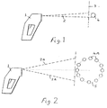
- FIG. 1 of the drawings there is shown a radiometer instrument 1 incorporating a laser beam production means which produces a single axial laser beam 2 which is directed at a target 3 and produces on the target an illuminated spot 4.
- FIG. 3 of the drawings there is shown a further embodment 6 of radiometer instrument which has at its front end a demountable attachment 6A which is adjustable, in the manner described below with reference to Figures 4 and 5, to produce selectively a single axial laser beam and a plurality of spaced laser beams for defining an area of a target;
- the attachment in a preferred embodiment of the best known mode incorporates a slide 7 which has in it a first opening 8 containing an attenuator device, and a second opening 9 containing a beam splitter lens.
- the attenuator in opening 8 is presented in front of the laser beam source and reduces the strength of the single axial laser beam produced.
- the beam splitter in opening 9 is presented in front of the laser beam source, and a plurality of beams (2A in Figure 2) are produced.
- a slideway 10 for mounting on the radiometer instrument having undercut lateral arms 11,11 in which the slide can move vertically, and upper and lower stops 12 and 13 limiting the up and down movement of the slide .
- a slide 14 for mounting on the front of the instrument has a plain opening 15 at its upper part, and a beam splitter lens 16 at its lower part.
- the slide 14 is movable vertically within limits, in a slideway, similar to that shown in Figure 4 for mounting on the radiometer instrument.
- On one side of the slide 14 there is mounted a lug 17 which is positioned to engage with a switch arm 18 on the instrument.
- the switch is incorporated in the power circuitry of the laser in the radiometer 6 ( Figure 3) and according to the raised or lowered position of the switch arm 18, as the case may, the laser is operated at full power or lowered power.
- the power of the laser is at a reduced scale which is safe and acceptable in use.
- the power of the laser is at an increased scale so that the plurality of beams produced by the splitter can each have adequate increased power for acceptable visibility on the target.
- the attachment may serve as an "add on” item which can be used for upgrading of existing laser radiometers and like instruments in which a wide differentiation between the power of the single beam, and of the plurality of beams, would otherwise be detrimental.
- Some existing radiometers may incorporate means to vary the laser brightness, but with the present invention there is the assurance that the brightness will be automatically maintained at a preferred level within safety limits.
- Another way in which the power used in each beam, and particularly in the greater number of beams, can vary is to pulse the laser so as to have periods of being "on” and “off", or of lower average power and higher average power,alternately, with the result that a higher power laser can be used in a unit having average optical power output.
- Attenuator means Change of the power utilised, from and into the respective factor, is obtained in a further embodiment of the invention by the use of attenuator means.
- an attenuator in one embodiment, is a member which is movable, say by sliding or twisting, by the operator or by a mechanism controlled by the operator or set to operate automatically so as to present different configurations such as patterns, or obscured or non-obscured areas, or areas having varied degrees of attenuation, in the path of the or each beam.
- the attenuator such as an adjustable iris
- the attenuator is arranged to vary the focus and brightness of an optical device through which the beam or beams is or are passed.
- the attenuator is linked to the beam-changing means so that when the number of subsidiary beams is increased, which would otherwise reduce their individual power proportionately, the power of the main beam, or beams, is increased proportionately. This may result in the original output power of the main beam or beams being greater than the safety limits mentioned above but the visible output of the apparatus at the target can still remain within the safety limits.
- such an attenuator is incorporated in, for example, a movable member such as a turret or slide linked to a manual change-over control of the apparatus, or actuated automatically and sequenced in synchronism with the sequenced changing over of the single beam to multiple beam operation.
- the laser light in another embodiment, is passed through a shutter mechanism which is automatic or manual.
- the attenuator is a beam splitting system which permits only a portion of a beam to be transmitted, or else is a beam-strength-reducing arrangement such as a partially opaque screen, or an opaque disk centered in the beam.
- a plurality of separate beams are disposed along a circle or other area-defining figure, in accordance with a further embodiment of the invention they are caused to move step-by-step, or in continuous motion, along the area-defining figure, e.g. the perimeter thereof, whilst being pulsed simultaneously or sequentially "on” and “off” at a rate, so that to the observer the area-defining figure remains constantly illuminated, as a result of the latent image effect.
- a laser of higher power that is otherwise used in a single continuous, i.e. non-interrupted, beam can be pulsed so as to produce a plurality of beams, e.g. twelve beams each having a pulsing rate for one-twelfth the time of a continuous beam.
- the viewer's eye retention will, in effect, cause the circle to appear as twelve brighter illuminated spots.
- the movement of the plurality of beams is obtained automatically, electronically or mechanically, or by manual actuation by the user of the apparatus, and the pulsing simultaneously and/or sequentially "on” and “off", i.e. the variation of strength, is obtained by variation of power used to generate the beam, or by variation of the proportion of the beam utilised, for example by beam-splitting mechanism such as a multiple-mirror system , or a masking device with areas of different masking capability.
- the beam splitter is arranged to provide laser beam spots not only at the periphery of the target area, but also within the target area, including at the center thereof.
- the beam splitter is arranged to provide dots, or other illuminated areas, in shapes other than a circle, and for example in the form of a cross.
- means provided for the front end of a laser beam generating instrument for example on a pyrometer, for varying the nature of the beam emitted, are made as an attachment in the form of a separate entity which is mounted removably on the instrument, so as for example to be attachable and detachable, for example utilising a self-tapping thread, as and when desired, and so that attachments with different beam-varying properties may be utilised as required.
- the attachments may conveniently have relatively movable portions, for example in the form of a slideway, for mounting on the instrument, and a slide movable in the slideway into respective positions in which different forms or degrees of modification of the laser beam are obtained.
- such a movable portion may have positions in which it presents respectively a simple opening or a beam splitter in the path of the laser beam, or again in which it presents a beam attenuator and a beam splitter in the path of the beam.
- the movable portion of the attachment may serve to actuate switching means, on the instrument, arranged to vary the strength of the laser beam appropriately.
- the attachment provides selective production of, for example, a single central beam of relatively higher power, for aiming at a target to permit accurate sighting on a selected area of the target, combined with a plurality of other or split beams directed at the target for outlining an area thereof, or for producing a pattern of spots on the target.
- the plurality of beams may be shifted from time to time, say in a circle, so as more clearly to outline a selected area of the target.
- the attachment provides projection of split beams which strike the target as a closed loop figure, such as a circle.
- the attachment is constructed to divert a single laser beam to strike successive plural points on a target so as effectively to outline an area thereof, and preferably with a rapidity sufficient to result in persistence of vision giving the impression of a full continuous illumination of the line of successive points.
Landscapes
- Physics & Mathematics (AREA)
- General Physics & Mathematics (AREA)
- Spectroscopy & Molecular Physics (AREA)
- Optics & Photonics (AREA)
- Astronomy & Astrophysics (AREA)
- Photometry And Measurement Of Optical Pulse Characteristics (AREA)
- Radiation Pyrometers (AREA)
- Lasers (AREA)
- Spectrometry And Color Measurement (AREA)
- Optical Couplings Of Light Guides (AREA)
- Optical Head (AREA)
- Supporting Of Heads In Record-Carrier Devices (AREA)
- Laser Surgery Devices (AREA)
Claims (7)
- Instrument mit Mitteln zum Erzeugen eines primären Laserstrahls, der hiervon entlang eines Pfades auf ein Ziel zu emittiert wird, wobei das Instrument mit einer Zusatzeinrichtung (6A) ausgestattet ist, wobei die Zusatzeinrichtung (6A) aufweist:wobei die Steuerpositionen eine erste Position, bei der der Träger von dem primären Strahl durchquert wird, und eine zweite Position aufweisen, bei der der primäre Strahl mittels der jeweiligen Strahl-Modifizierungsmittel in eine Vielzahl von sekundären Strahlen aufgeteilt wird; und(i) eine Rumpfstruktur (10, 11), die an dem Instrument montiert ist,(ii) einen Träger (7; 14), der an der Rumpfstruktur gelagert ist, wobei der Träger in Bezug auf die Rumpfstruktur relativ zu dem Pfad des primären Strahls in eine Vielzahl von Steuerpositionen bewegbar ist, wobei der Träger Laserstrahl-Modifizierungsmittel (9; 8; 16) aufweist, die gemäß der Position des Trägers relativ zu dem Pfad jeweils in dem Pfad vorhanden sein können,
wobei Mittel (8) vorgesehen sind, um die Leistung des primären Strahls zu dämpfen, wenn der Träger sich in der ersten Position befindet. - Instrument nach Anspruch 1, wobei der Träger (7; 14) in Bezug auf die Rumpfstruktur (6A) verschiebbar ist, und zwar zur Bewegung in die relativen Positionen und aus den relativen Positionen heraus.
- Instrument nach Anspruch 1 oder 2, wobei die Laserstrahl-Modifizierungsmittel des Trägers einen Laserstrahlteiler (9; 16) aufweisen, der in der zweiten Position des Trägers in dem Pfad vorhanden ist.
- Instrument nach Anspruch 3, wobei der Laserstrahlteiler (9; 16) eine Diffraktionslinse ist.
- Instrument nach einem der vorhergehenden Ansprüche, wobei die Laserstrahl-Modifizierungsmittel des Trägers (7; 14) einen Laserstrahldämpfer (8) aufweisen, der in der ersten Position des Trägers in dem Pfad vorhanden ist.
- Instrument nach einem der Ansprüche 1 bis 4, mit Mitteln (18) an dem Instrument zum Variieren der Leistung des primären Strahls, und mit Mitteln (17) an dem Träger (14), positioniert, um die Leistungsvariierungsmittel (18) gemäß der relativen Position des Trägers zu betätigen.
- Instrument nach einem der vorhergehenden Ansprüche, mit einem in der Hand zu haltenden Radiometer zum Bestimmen von einer Entfernung aus der Temperatur einer Zieloberfläche, wobei das Instrument eine Laservisiereinrichtung verwendet, die die Mittel zum Erzeugen des primären Laserstrahls beinhalten.
Applications Claiming Priority (8)
| Application Number | Priority Date | Filing Date | Title |
|---|---|---|---|
| US15459199P | 1999-09-17 | 1999-09-17 | |
| US154591P | 1999-09-17 | ||
| US18538500P | 2000-02-28 | 2000-02-28 | |
| US185385P | 2000-02-28 | ||
| US18740000P | 2000-03-07 | 2000-03-07 | |
| US187400P | 2000-03-07 | ||
| US19838400P | 2000-04-19 | 2000-04-19 | |
| US198384 | 2000-04-19 |
Publications (3)
| Publication Number | Publication Date |
|---|---|
| EP1085307A1 EP1085307A1 (de) | 2001-03-21 |
| EP1085307B1 true EP1085307B1 (de) | 2005-11-23 |
| EP1085307B8 EP1085307B8 (de) | 2006-01-25 |
Family
ID=27496137
Family Applications (1)
| Application Number | Title | Priority Date | Filing Date |
|---|---|---|---|
| EP00308107A Expired - Lifetime EP1085307B8 (de) | 1999-09-17 | 2000-09-18 | Zusatzgerät zur Regelung der Strahlverteilung eines Laserzeigers |
Country Status (6)
| Country | Link |
|---|---|
| EP (1) | EP1085307B8 (de) |
| JP (1) | JP4527865B2 (de) |
| AT (1) | ATE310944T1 (de) |
| CA (1) | CA2319880C (de) |
| DE (1) | DE60024187T2 (de) |
| ES (1) | ES2253187T3 (de) |
Families Citing this family (8)
| Publication number | Priority date | Publication date | Assignee | Title |
|---|---|---|---|---|
| US20060056484A1 (en) * | 2004-09-16 | 2006-03-16 | Hollander Milton B | Laser modification |
| ES2380087T3 (es) * | 2003-07-14 | 2012-05-08 | White Box Inc. | Sistema de láser |
| EP1649256B1 (de) * | 2003-07-30 | 2010-01-20 | Optris GmbH | Vorrichtung zur beruhrungslosen temperaturmessung |
| JP4590858B2 (ja) * | 2003-11-18 | 2010-12-01 | 富士ゼロックス株式会社 | 書き込み可能プロジェクタおよび光ポインタ |
| US8240912B2 (en) | 2008-08-15 | 2012-08-14 | Fluke Corporation | Multi-zone non-contact spot thermometer |
| USD794858S1 (en) | 2016-02-19 | 2017-08-15 | Prime Wire & Cable, Inc. | Laser light projector |
| USD794859S1 (en) | 2016-02-19 | 2017-08-15 | Prime Wire & Cable, Inc. | Laser light projector |
| USD791993S1 (en) | 2016-02-19 | 2017-07-11 | Prime Wire & Cable, Inc. | Combined laser light projector and remote control |
Family Cites Families (7)
| Publication number | Priority date | Publication date | Assignee | Title |
|---|---|---|---|---|
| JPH04333092A (ja) * | 1991-05-08 | 1992-11-20 | Omron Corp | 光指示装置 |
| JPH06265817A (ja) * | 1993-03-12 | 1994-09-22 | Toko Inc | レーザポインタ |
| US5368392B1 (en) * | 1993-09-17 | 1998-11-03 | Omega Engineering | Method and apparatus for measuring temperature using infrared techniques |
| US5823679A (en) * | 1993-09-17 | 1998-10-20 | Omega Engineering, Inc. | Method and apparatus for measuring temperature including aiming light |
| US5450148A (en) * | 1994-04-18 | 1995-09-12 | Yu S. Lin | Laser pointer with selectable pointer patterns |
| JPH08122701A (ja) * | 1994-10-20 | 1996-05-17 | Moritetsukusu:Kk | レーザポインタ |
| JPH09160128A (ja) * | 1995-12-12 | 1997-06-20 | Olympus Optical Co Ltd | ポインター投影装置 |
-
2000
- 2000-09-15 CA CA2319880A patent/CA2319880C/en not_active Expired - Fee Related
- 2000-09-18 JP JP2000281208A patent/JP4527865B2/ja not_active Expired - Fee Related
- 2000-09-18 AT AT00308107T patent/ATE310944T1/de not_active IP Right Cessation
- 2000-09-18 DE DE60024187T patent/DE60024187T2/de not_active Expired - Lifetime
- 2000-09-18 ES ES00308107T patent/ES2253187T3/es not_active Expired - Lifetime
- 2000-09-18 EP EP00308107A patent/EP1085307B8/de not_active Expired - Lifetime
Also Published As
| Publication number | Publication date |
|---|---|
| CA2319880A1 (en) | 2001-03-17 |
| EP1085307B8 (de) | 2006-01-25 |
| JP4527865B2 (ja) | 2010-08-18 |
| EP1085307A1 (de) | 2001-03-21 |
| CA2319880C (en) | 2012-03-13 |
| DE60024187T2 (de) | 2006-08-03 |
| ATE310944T1 (de) | 2005-12-15 |
| DE60024187D1 (de) | 2005-12-29 |
| ES2253187T3 (es) | 2006-06-01 |
| JP2001166256A (ja) | 2001-06-22 |
Similar Documents
| Publication | Publication Date | Title |
|---|---|---|
| US6377400B1 (en) | Laser sighting beam modification for measuring or treatment instrument | |
| US6901089B1 (en) | Laser instrument | |
| US6572229B2 (en) | Back projection visual field tester | |
| JPH033206B2 (de) | ||
| EP1085307B1 (de) | Zusatzgerät zur Regelung der Strahlverteilung eines Laserzeigers | |
| US20090294671A1 (en) | Target brightness | |
| EA034274B1 (ru) | Операционная осветительная система и способ выведения инструкций по настройке освещения для оператора указанной осветительной системы | |
| JP2004033744A (ja) | 携帯型の眼科装置用の調整システム | |
| US6614830B1 (en) | Laser beam adjustment | |
| US7692857B2 (en) | Device for varying and adjusting transmitted illumination for microscopes | |
| CA2740929C (en) | Laser beam adjustment | |
| US7897908B2 (en) | Radiometer sighting device and method | |
| US8110803B2 (en) | Sighting system and method | |
| EP0624422B1 (de) | Zustandzeigevorrichtung für einem Laserstrahl | |
| US20020005934A1 (en) | Device for testing visual functions of the human eye | |
| EP1637851A1 (de) | Laservisiergerät mit Strahlmodifikation | |
| JP2768955B2 (ja) | レンズメータ | |
| EA009998B1 (ru) | Способ и устройство для получения изображений в пространстве | |
| Bullough et al. | Luminous Intensity for Traffic Signals: A Scientific Basis for Performance Specifications | |
| JPH0735984A (ja) | 光学測定機の照明装置 | |
| UA50587A (uk) | Нашоломна система цілевказування та індикації | |
| CHISUM | Display Visual Design | |
| JP2000174363A (ja) | レーザ検知器評価装置 | |
| AU2002317804A1 (en) | Back projection visual field tester |
Legal Events
| Date | Code | Title | Description |
|---|---|---|---|
| PUAI | Public reference made under article 153(3) epc to a published international application that has entered the european phase |
Free format text: ORIGINAL CODE: 0009012 |
|
| AK | Designated contracting states |
Kind code of ref document: A1 Designated state(s): AT BE CH CY DE DK ES FI FR GB GR IE IT LI LU MC NL PT SE |
|
| AX | Request for extension of the european patent |
Free format text: AL;LT;LV;MK;RO;SI |
|
| 17P | Request for examination filed |
Effective date: 20010831 |
|
| AKX | Designation fees paid |
Free format text: AT BE CH CY DE DK ES FI FR GB GR IE IT LI LU MC NL PT SE |
|
| 17Q | First examination report despatched |
Effective date: 20040422 |
|
| GRAP | Despatch of communication of intention to grant a patent |
Free format text: ORIGINAL CODE: EPIDOSNIGR1 |
|
| GRAS | Grant fee paid |
Free format text: ORIGINAL CODE: EPIDOSNIGR3 |
|
| GRAA | (expected) grant |
Free format text: ORIGINAL CODE: 0009210 |
|
| AK | Designated contracting states |
Kind code of ref document: B1 Designated state(s): AT BE CH CY DE DK ES FI FR GB GR IE IT LI LU MC NL PT SE |
|
| PG25 | Lapsed in a contracting state [announced via postgrant information from national office to epo] |
Ref country code: LI Free format text: LAPSE BECAUSE OF FAILURE TO SUBMIT A TRANSLATION OF THE DESCRIPTION OR TO PAY THE FEE WITHIN THE PRESCRIBED TIME-LIMIT Effective date: 20051123 Ref country code: FI Free format text: LAPSE BECAUSE OF FAILURE TO SUBMIT A TRANSLATION OF THE DESCRIPTION OR TO PAY THE FEE WITHIN THE PRESCRIBED TIME-LIMIT Effective date: 20051123 Ref country code: AT Free format text: LAPSE BECAUSE OF FAILURE TO SUBMIT A TRANSLATION OF THE DESCRIPTION OR TO PAY THE FEE WITHIN THE PRESCRIBED TIME-LIMIT Effective date: 20051123 Ref country code: BE Free format text: LAPSE BECAUSE OF FAILURE TO SUBMIT A TRANSLATION OF THE DESCRIPTION OR TO PAY THE FEE WITHIN THE PRESCRIBED TIME-LIMIT Effective date: 20051123 Ref country code: CH Free format text: LAPSE BECAUSE OF FAILURE TO SUBMIT A TRANSLATION OF THE DESCRIPTION OR TO PAY THE FEE WITHIN THE PRESCRIBED TIME-LIMIT Effective date: 20051123 |
|
| REG | Reference to a national code |
Ref country code: GB Ref legal event code: FG4D |
|
| REG | Reference to a national code |
Ref country code: CH Ref legal event code: EP |
|
| RAP2 | Party data changed (patent owner data changed or rights of a patent transferred) |
Owner name: WHITE BOX INC. |
|
| RIN2 | Information on inventor provided after grant (corrected) |
Inventor name: HOLLANDER, MILTON BERNARD |
|
| REF | Corresponds to: |
Ref document number: 60024187 Country of ref document: DE Date of ref document: 20051229 Kind code of ref document: P |
|
| REG | Reference to a national code |
Ref country code: IE Ref legal event code: FG4D |
|
| PG25 | Lapsed in a contracting state [announced via postgrant information from national office to epo] |
Ref country code: DK Free format text: LAPSE BECAUSE OF FAILURE TO SUBMIT A TRANSLATION OF THE DESCRIPTION OR TO PAY THE FEE WITHIN THE PRESCRIBED TIME-LIMIT Effective date: 20060223 Ref country code: GR Free format text: LAPSE BECAUSE OF FAILURE TO SUBMIT A TRANSLATION OF THE DESCRIPTION OR TO PAY THE FEE WITHIN THE PRESCRIBED TIME-LIMIT Effective date: 20060223 |
|
| NLT2 | Nl: modifications (of names), taken from the european patent patent bulletin |
Owner name: WHITE BOX INC. Effective date: 20051228 |
|
| REG | Reference to a national code |
Ref country code: SE Ref legal event code: TRGR |
|
| PG25 | Lapsed in a contracting state [announced via postgrant information from national office to epo] |
Ref country code: PT Free format text: LAPSE BECAUSE OF FAILURE TO SUBMIT A TRANSLATION OF THE DESCRIPTION OR TO PAY THE FEE WITHIN THE PRESCRIBED TIME-LIMIT Effective date: 20060424 |
|
| REG | Reference to a national code |
Ref country code: CH Ref legal event code: PL |
|
| REG | Reference to a national code |
Ref country code: ES Ref legal event code: FG2A Ref document number: 2253187 Country of ref document: ES Kind code of ref document: T3 |
|
| ET | Fr: translation filed | ||
| PG25 | Lapsed in a contracting state [announced via postgrant information from national office to epo] |
Ref country code: IE Free format text: LAPSE BECAUSE OF NON-PAYMENT OF DUE FEES Effective date: 20060918 |
|
| PLBE | No opposition filed within time limit |
Free format text: ORIGINAL CODE: 0009261 |
|
| STAA | Information on the status of an ep patent application or granted ep patent |
Free format text: STATUS: NO OPPOSITION FILED WITHIN TIME LIMIT |
|
| PG25 | Lapsed in a contracting state [announced via postgrant information from national office to epo] |
Ref country code: MC Free format text: LAPSE BECAUSE OF NON-PAYMENT OF DUE FEES Effective date: 20060930 |
|
| 26N | No opposition filed |
Effective date: 20060824 |
|
| REG | Reference to a national code |
Ref country code: IE Ref legal event code: MM4A |
|
| PG25 | Lapsed in a contracting state [announced via postgrant information from national office to epo] |
Ref country code: LU Free format text: LAPSE BECAUSE OF NON-PAYMENT OF DUE FEES Effective date: 20060918 |
|
| PG25 | Lapsed in a contracting state [announced via postgrant information from national office to epo] |
Ref country code: CY Free format text: LAPSE BECAUSE OF FAILURE TO SUBMIT A TRANSLATION OF THE DESCRIPTION OR TO PAY THE FEE WITHIN THE PRESCRIBED TIME-LIMIT Effective date: 20051123 |
|
| REG | Reference to a national code |
Ref country code: FR Ref legal event code: TP Owner name: WHITE BOX, INC., US Effective date: 20110922 |
|
| PGFP | Annual fee paid to national office [announced via postgrant information from national office to epo] |
Ref country code: DE Payment date: 20130919 Year of fee payment: 14 Ref country code: ES Payment date: 20130918 Year of fee payment: 14 Ref country code: SE Payment date: 20130919 Year of fee payment: 14 Ref country code: NL Payment date: 20130918 Year of fee payment: 14 |
|
| PGFP | Annual fee paid to national office [announced via postgrant information from national office to epo] |
Ref country code: GB Payment date: 20130919 Year of fee payment: 14 Ref country code: FR Payment date: 20130919 Year of fee payment: 14 |
|
| PGFP | Annual fee paid to national office [announced via postgrant information from national office to epo] |
Ref country code: IT Payment date: 20130930 Year of fee payment: 14 |
|
| REG | Reference to a national code |
Ref country code: DE Ref legal event code: R119 Ref document number: 60024187 Country of ref document: DE |
|
| REG | Reference to a national code |
Ref country code: SE Ref legal event code: EUG |
|
| GBPC | Gb: european patent ceased through non-payment of renewal fee |
Effective date: 20140918 |
|
| PG25 | Lapsed in a contracting state [announced via postgrant information from national office to epo] |
Ref country code: SE Free format text: LAPSE BECAUSE OF NON-PAYMENT OF DUE FEES Effective date: 20140919 |
|
| REG | Reference to a national code |
Ref country code: DE Ref legal event code: R119 Ref document number: 60024187 Country of ref document: DE Effective date: 20150401 |
|
| REG | Reference to a national code |
Ref country code: FR Ref legal event code: ST Effective date: 20150529 |
|
| PG25 | Lapsed in a contracting state [announced via postgrant information from national office to epo] |
Ref country code: NL Free format text: LAPSE BECAUSE OF NON-PAYMENT OF DUE FEES Effective date: 20150401 |
|
| PG25 | Lapsed in a contracting state [announced via postgrant information from national office to epo] |
Ref country code: GB Free format text: LAPSE BECAUSE OF NON-PAYMENT OF DUE FEES Effective date: 20140918 Ref country code: DE Free format text: LAPSE BECAUSE OF NON-PAYMENT OF DUE FEES Effective date: 20150401 |
|
| PG25 | Lapsed in a contracting state [announced via postgrant information from national office to epo] |
Ref country code: FR Free format text: LAPSE BECAUSE OF NON-PAYMENT OF DUE FEES Effective date: 20140930 Ref country code: IT Free format text: LAPSE BECAUSE OF NON-PAYMENT OF DUE FEES Effective date: 20140918 |
|
| REG | Reference to a national code |
Ref country code: ES Ref legal event code: FD2A Effective date: 20151028 |
|
| PG25 | Lapsed in a contracting state [announced via postgrant information from national office to epo] |
Ref country code: ES Free format text: LAPSE BECAUSE OF NON-PAYMENT OF DUE FEES Effective date: 20140919 |