EP1085545A2 - Appareil de commutation - Google Patents
Appareil de commutation Download PDFInfo
- Publication number
- EP1085545A2 EP1085545A2 EP00119862A EP00119862A EP1085545A2 EP 1085545 A2 EP1085545 A2 EP 1085545A2 EP 00119862 A EP00119862 A EP 00119862A EP 00119862 A EP00119862 A EP 00119862A EP 1085545 A2 EP1085545 A2 EP 1085545A2
- Authority
- EP
- European Patent Office
- Prior art keywords
- projection
- switch
- operating knob
- movable member
- guide hole
- Prior art date
- Legal status (The legal status is an assumption and is not a legal conclusion. Google has not performed a legal analysis and makes no representation as to the accuracy of the status listed.)
- Withdrawn
Links
Images


Classifications
-
- H—ELECTRICITY
- H01—ELECTRIC ELEMENTS
- H01H—ELECTRIC SWITCHES; RELAYS; SELECTORS; EMERGENCY PROTECTIVE DEVICES
- H01H25/00—Switches with compound movement of handle or other operating part
- H01H25/002—Switches with compound movement of handle or other operating part having an operating member rectilinearly slidable in different directions
-
- H—ELECTRICITY
- H01—ELECTRIC ELEMENTS
- H01H—ELECTRIC SWITCHES; RELAYS; SELECTORS; EMERGENCY PROTECTIVE DEVICES
- H01H2300/00—Orthogonal indexing scheme relating to electric switches, relays, selectors or emergency protective devices covered by H01H
- H01H2300/008—Application power seats
Definitions
- the present invention relates a switch assembly structure in which a first switch element and a second switch element are adapted to be selectively operated by a single operating knob.
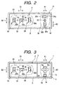
- Fig. 3 shows a schematic plan view of a power seat switch in a vehicle.
- This power seat switch is composed of a first switch device 1 on the right side and a second switch device 2 on the left side.
- a cover 4 corresponding to the first switch device 1 and a cover 5 corresponding to the second switch device 2 are mounted on a common switch body 3.
- the first switch device 1 is so constructed as to operate a reclining switch for adjusting a reclined angle of a back of a seat and a head restraint switch for adjusting a height of a head restraint provided on a top of the seat back.
- a guide hole 4a in a shape of a cross and a cut-out 4b so as to be adjacent to each other as shown in Fig. 4.
- a projection 3a provided on a switch body 3 is inserted into the cut-out 4b and projects upward from the cover 4.
- a plate 6 is fixed to the switch body 3 underneath the cover 4.
- the plate 6 is provided with a guide hole 6a in a shape of a cross, and an elongated guide hole 6b so as to be adjacent to each other.
- a knob holder 7 is slidably mounted on the plate 6.
- the knob holder 7 has a projection 7a which is adapted to be inserted into the guide hole 4a on its upper face, and two projections 7b and 7c which are adapted to be inserted into the guide holes 6a and 6b respectively on its lower face.
- Two holders 8, 9 are disposed underneath the plate 6 at positions below the guide holes 6a and 6b, respectively.
- the corresponding projections 7b and 7c are adapted to be inserted.
- the recess 8a of the holder 8 into which one of the projections 7b is inserted extends in a direction of an arrow A1
- the recess 9a of the holder 9 into which the other projection 7c is inserted extends in a direction of an arrow A2 which intersects the direction A1.
- a coil spring 10, a bifurcated member 11, and a pair of contact blades 12 are disposed below each of the holders 8, 9.
- the switch body 3 is provided with fixed contacts (not shown) corresponding to the contact blades 12 respectively.
- a pair of the contact blades 12 corresponding to the holder 9 and the mating fixed contacts constitutes the reclining switch 13 as a switch element, while a pair of the contact blades 12 corresponding to the holder 8 and the mating fixed contacts will constitute the head restraint switch 14 as a switch element.
- a single operating knob 15 is fitted to the above described projection 3a and the projection 7a of the knob holder 7.
- a guide part 16 consisting of a pair of ribs 16a, and an engaging tubular part 17 are provided on a back face of the operating knob 15. The projection 3a is inserted into the guide part 16, and the projection 7a is inserted into the engaging tubular part 17.
- the second switch device 2 on the left side has a front vertical switch 18 for adjusting a front part of the seat in a vertical direction, a slide switch 19 for adjusting back and forth positions of the seat, and a rear vertical switch 20 for adjusting a rear part of the seat in a vertical direction.
- These three switches 18 19, and 20 are adapted to be operated by a single operating knob 21.
- These three switches 18, 19 and 20 are of a same fundamental structure. As shown in Fig. 5, each of the switches 18, 19 and 20 is composed of a movable member 22 provided with a projection 22a, and a coil spring 10, a bifurcated member 11, a pair of contact blades 12 and fixed contacts (not shown) on the switch body 3 which are similar to those elements provided in the switches 13, 14.
- the aforesaid cover 5 is provided with three guide holes 5a, 5b and 5c into which the projections 22a of the movable members 22 are inserted respectively.
- the center guide hole 5b extends in a direction of an arrow B1 in Fig. 3.
- the projection 22a of the corresponding movable member 22 is inserted into the guide hole 5b.
- the left and right guide holes 5a and 5c extend in a direction of an arrow B2 in Fig. 3, and the projections 22a of the corresponding movable members 22 are respectively inserted into the guide holes 5a and 5c.
- both the left hand and the right hand movable members 22 synchronously move in the same direction, and both the front and the rear vertical switches 18, 20 are actuated. On this occasion, the center movable member 22 does not move, and the slide switch 19 is not actuated.
- the above described first switch device is so constructed that the single operating knob 15 can selectively actuate either of the reclining switch 13 and the head restraint switch 14. On this occasion, these two switches 13 and 14 are prevented from being simultaneously actuated by the two projections 7b, 7c provided on the lower face of the knob holder 7 and the two guide holes 6a, 6c of the plate 6.
- a cost for the switch assembly of this structure is high, because it requires a number of components such as the knob holder 7, the plate 6 and the two holders 8, 9 in addition to the operating knob 15 and the cover 4, and a number of assembling steps accordingly.
- the knob holder 7, the plate 6 and the holders 8, 9 cannot be used commonly as the components for the second switch device 2, and must be manufactured for exclusive use. It is a further drawback that a large space is required in a direction of a depth.
- the present invention has been made in view of the above described circumstances.
- the object is to provide a switch assembly of a structure in which two switch elements can be selectively actuated by operating a single operating knob, and the number of the components can be decreased, and the space in a direction of the depth can be minimized.
- a switch assembly which comprises;
- the first movable member when the second guide part of the operating knob is operated in the first direction, the first movable member is moved in the first direction along the first guide hole by way of the first projection by means of the second guide part, and the first switch element is actuated accordingly.
- the third guide part of the operating knob is operated in the second direction, the second movable member is moved in the second direction along the second guide hole by way of the second projection by means of the third guide part, and the second switch element is actuated accordingly.
- the two switch elements is prevented from being synchronously operated by means of the first guide part of the operating knob.
- this structure requires the first and the second movable members as the movable members to be operated by the operating knob, the exclusive knob holders, the plate, and the two holders which have been required in the conventional structure are not necessary, thus enabling the number of the components to be reduced. Moreover, because the number of the components is reduced in the direction of the depth, the space in the direction of the depth can be minimized.
- Figs. 1 and 2 the invention will be described by way of an embodiment in which the invention is applied to a power seat switch assembly in a vehicle.
- those parts which are same as in the conventional case will be denoted with the same reference numerals to omit their explanation, and different parts only will be described.
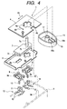
- a cover 32 is integrally formed with the cover 5 of the second switch device 2.
- the cover 32 is provided with a first guide hole 32a which extends in the direction of the arrow A1 in this case, and a second guide hole 32b which extends in the direction of the arrow A2 in this case.
- An intermediate projection 33 is provided on an upper face of the cover 32 between the first guide hole 32a and the second guide hole 32b projecting upward (in a direction opposite to the switch body 3).
- first movable member 34 having a first projection 34a adapted to be inserted into the first guide hole 32a
- second movable member 35 having a second projection 35a adapted to be inserted into the second guide hole 32b.
- Coil springs 10, bifurcated members 11, and pairs of contact blades 12 are provided at positions corresponding to these first and second movable members 34 and 35.
- the first and the second movable members 34 and 35 are of the same structure as the movable members 22 which are employed in the second switch device 2.
- the switch body 3 is provided with fixed contacts (not shown) corresponding to the contact blades 12 respectively.
- a pair of the contact blades 12 corresponding to the first movable member 34 and the mating fixed contacts constitute the reclining switch 13 as the first switch element.
- a pair of the contact blades 12 corresponding to the movable member 35 and the mating fixed contacts constitute the head restraint switch 14 as the second switch element.
- a single operating knob 36 is mounted on the intermediate projection 33, and the first and the second projections 34a and 35a.
- a first guide part 37 substantially in a shape of a cross composed of four L-shaped ribs 37a substantially at a center part
- a second guide part 38 composed of a pair of ribs 38a extending in the direction of the arrow A2 (the second direction) at a position corresponding to the first projection 34a
- a third guide part 39 composed of a pair of ribs 39a extending in the direction of the arrow A1 (the first direction) at a position corresponding to the second projection 35a are provided on a back face of the operating knob 36.
- the intermediate projection 33 is inserted into the first guide part 37 so as to be movable relatively in the direction of the arrow A1 and in the direction of the arrow A2.
- the first projection 34a is inserted into the second guide part 38 so as to be movable relatively in the direction of the arrow A2.
- the second projection 35a is inserted into the third guide part 39 so as to be movable relatively in the direction of the arrow A1.
- the second switch device 2 is of the same structure as the conventional case, and the explanation is omitted.
- the second movable member 35 is moved by means of the rib 39a of the third guide part 39 along the second guide hole 32b in the direction of the arrow A2 through the second projection 35a. Accordingly, the head restraint switch 14 is actuated. On this occasion, the first movable member 34 does not move, and the reclining switch 13 is not actuated.
- the first movable member 34 and the second movable member 35 are prevented from being operated to move in their operative directions at the same time by means of the intermediate projection 33 and the first guide part 37 of the operating knob 36. Therefore, a simultaneously actuation of the reclining switch 13 and the head restraint switch 14 is prevented.
- the exclusive knob holder 7 which have been required in the conventional case are not necessary. Therefore, the number of the components can be reduced and accordingly, the number of the assembling steps is reduced resulting in a decrease of the cost. Moreover, because the movable members 22 which are employed in the second switch device 2 can be employed as the first movable member 34 and the second movable member 35 in this embodiment, a common use of the components is possible to reduce the cost more. Further, because the number of the components in the direction of the depth is decreased, the space in the direction of the depth can be minimized.
- the switch assembly according to the invention is so constructed that the two switch elements can be selectively actuated by the single operating knob, the number of the components can be reduced, and the number of the assembling steps are reduced resulting in a decrease of the cost. Further, because the number of the components in the direction of the depth is decreased, the space in the direction of the depth can be minimized.
Landscapes
- Switches With Compound Operations (AREA)
- Seats For Vehicles (AREA)
- Switch Cases, Indication, And Locking (AREA)
Applications Claiming Priority (2)
| Application Number | Priority Date | Filing Date | Title |
|---|---|---|---|
| JP26188999 | 1999-09-16 | ||
| JP26188999A JP2001084873A (ja) | 1999-09-16 | 1999-09-16 | スイッチ装置 |
Publications (2)
| Publication Number | Publication Date |
|---|---|
| EP1085545A2 true EP1085545A2 (fr) | 2001-03-21 |
| EP1085545A3 EP1085545A3 (fr) | 2002-10-09 |
Family
ID=17368185
Family Applications (1)
| Application Number | Title | Priority Date | Filing Date |
|---|---|---|---|
| EP00119862A Withdrawn EP1085545A3 (fr) | 1999-09-16 | 2000-09-12 | Appareil de commutation |
Country Status (4)
| Country | Link |
|---|---|
| US (1) | US6262379B1 (fr) |
| EP (1) | EP1085545A3 (fr) |
| JP (1) | JP2001084873A (fr) |
| AU (1) | AU763947B2 (fr) |
Cited By (1)
| Publication number | Priority date | Publication date | Assignee | Title |
|---|---|---|---|---|
| DE20305537U1 (de) * | 2003-04-05 | 2004-08-05 | Metabowerke Gmbh | Elektrohandwerkzeuggerät und Schalter für Elektrohandwerkzeuggerät |
Families Citing this family (9)
| Publication number | Priority date | Publication date | Assignee | Title |
|---|---|---|---|---|
| JP3971098B2 (ja) * | 2000-11-09 | 2007-09-05 | 株式会社東海理化電機製作所 | 自動車用パワーシートスイッチ装置 |
| JP4184070B2 (ja) * | 2002-12-26 | 2008-11-19 | 矢崎総業株式会社 | ランプユニットの取付構造 |
| US7078641B2 (en) * | 2004-09-28 | 2006-07-18 | Lear Corporation | Switch Cell |
| US7291797B2 (en) * | 2005-12-30 | 2007-11-06 | Seikaku Technical Group Limited | Tuning structure of a sound mixer |
| DE102006042450A1 (de) * | 2006-09-09 | 2008-03-27 | Recaro Gmbh & Co. Kg | Bedieneinheit für wenigstens einen Einsteller eines Fahrzeugsitzes |
| JP4680170B2 (ja) * | 2006-11-29 | 2011-05-11 | トヨタ紡織株式会社 | 車両用シートの電動操作装置 |
| BRPI1007217A2 (pt) | 2009-01-21 | 2016-02-23 | Omron Dualtec Automotive Electronics Inc | comutador elétrico de assento para impedir ativação simultânea |
| JP5241587B2 (ja) * | 2009-04-13 | 2013-07-17 | トヨタ紡織株式会社 | スライドスイッチ構造体及びそれを用いたパワーシートスイッチ |
| JP6568815B2 (ja) * | 2016-03-02 | 2019-08-28 | アルプスアルパイン株式会社 | 操作装置 |
Family Cites Families (8)
| Publication number | Priority date | Publication date | Assignee | Title |
|---|---|---|---|---|
| JPS59103331U (ja) * | 1982-12-27 | 1984-07-11 | 株式会社東海理化電機製作所 | 車両用パワ−シ−ト・スイツチ |
| JPS59103331A (ja) * | 1983-09-21 | 1984-06-14 | Hitachi Ltd | プラズマ処理装置 |
| US5442149A (en) | 1990-10-17 | 1995-08-15 | Toyo Denso Kabushiki Kaisha | Switch apparatus for automobile |
| JPH04104025U (ja) | 1991-01-18 | 1992-09-08 | アルプス電気株式会社 | 車両用パワーシートスイツチ |
| US5384440A (en) | 1992-12-17 | 1995-01-24 | United Technologies Automotive, Inc. | Automotive seat switch assembly |
| JPH09240340A (ja) | 1996-03-01 | 1997-09-16 | Niles Parts Co Ltd | パワーシートスイッチ |
| JPH09306299A (ja) * | 1996-05-14 | 1997-11-28 | Yazaki Corp | スイッチ |
| US5866862A (en) | 1997-04-07 | 1999-02-02 | Ut Automotive Dearborn, Inc. | Vehicle positioning control |
-
1999
- 1999-09-16 JP JP26188999A patent/JP2001084873A/ja active Pending
-
2000
- 2000-09-08 US US09/658,875 patent/US6262379B1/en not_active Expired - Fee Related
- 2000-09-12 EP EP00119862A patent/EP1085545A3/fr not_active Withdrawn
- 2000-09-14 AU AU59433/00A patent/AU763947B2/en not_active Ceased
Cited By (1)
| Publication number | Priority date | Publication date | Assignee | Title |
|---|---|---|---|---|
| DE20305537U1 (de) * | 2003-04-05 | 2004-08-05 | Metabowerke Gmbh | Elektrohandwerkzeuggerät und Schalter für Elektrohandwerkzeuggerät |
Also Published As
| Publication number | Publication date |
|---|---|
| AU5943300A (en) | 2001-03-22 |
| US6262379B1 (en) | 2001-07-17 |
| EP1085545A3 (fr) | 2002-10-09 |
| JP2001084873A (ja) | 2001-03-30 |
| AU763947B2 (en) | 2003-08-07 |
Similar Documents
| Publication | Publication Date | Title |
|---|---|---|
| EP1863047B1 (fr) | Interrupteur à coulisse | |
| EP1764815B1 (fr) | Interrupteur | |
| US5442149A (en) | Switch apparatus for automobile | |
| US6262379B1 (en) | Switch apparatus | |
| US6515241B2 (en) | Power seat switch apparatus for vehicle | |
| EP3780052B1 (fr) | Dispositif de commutateur | |
| JP3673339B2 (ja) | スイッチ装置 | |
| EP2088608B1 (fr) | Siege de vehicule avec un dispositif de commande electrique | |
| US6541716B2 (en) | Multidirectional switch device in which differences in tactile feel are reduced | |
| US20020104742A1 (en) | Multifunction switch assembly for power adjusted vehicle passenger seat | |
| JP3406800B2 (ja) | コントロールスイッチ | |
| JP2001135196A (ja) | スライド操作式スイッチ | |
| US5735391A (en) | Dual slide three-position switch | |
| US9741510B2 (en) | Switch device | |
| KR102854191B1 (ko) | 차량용 스위치 장치 | |
| JP3593690B2 (ja) | スイッチ装置 | |
| JP2000285765A (ja) | センタープッシュ機構を有するスライドスイッチ | |
| KR20170090984A (ko) | 차량용 스위치 장치 | |
| JP3183794B2 (ja) | スライドスイッチ | |
| CN119975138A (zh) | 头枕 | |
| CN119975140A (zh) | 头枕 | |
| JPH0436015Y2 (fr) | ||
| CN119975137A (zh) | 头枕 | |
| JPH0741926U (ja) | スイッチ装置 | |
| JP2009129629A (ja) | パワーシートの操作スイッチ |
Legal Events
| Date | Code | Title | Description |
|---|---|---|---|
| PUAI | Public reference made under article 153(3) epc to a published international application that has entered the european phase |
Free format text: ORIGINAL CODE: 0009012 |
|
| AK | Designated contracting states |
Kind code of ref document: A2 Designated state(s): AT BE CH CY DE DK ES FI FR GB GR IE IT LI LU MC NL PT SE |
|
| AX | Request for extension of the european patent |
Free format text: AL;LT;LV;MK;RO;SI |
|
| PUAL | Search report despatched |
Free format text: ORIGINAL CODE: 0009013 |
|
| AK | Designated contracting states |
Kind code of ref document: A3 Designated state(s): AT BE CH CY DE DK ES FI FR GB GR IE IT LI LU MC NL PT SE |
|
| AX | Request for extension of the european patent |
Free format text: AL;LT;LV;MK;RO;SI |
|
| 17P | Request for examination filed |
Effective date: 20021126 |
|
| AKX | Designation fees paid |
Designated state(s): DE FR GB |
|
| STAA | Information on the status of an ep patent application or granted ep patent |
Free format text: STATUS: THE APPLICATION IS DEEMED TO BE WITHDRAWN |
|
| 18D | Application deemed to be withdrawn |
Effective date: 20060105 |