EP1085609A1 - Contact à douille électrique avec un rail de guidage - Google Patents
Contact à douille électrique avec un rail de guidage Download PDFInfo
- Publication number
- EP1085609A1 EP1085609A1 EP00119427A EP00119427A EP1085609A1 EP 1085609 A1 EP1085609 A1 EP 1085609A1 EP 00119427 A EP00119427 A EP 00119427A EP 00119427 A EP00119427 A EP 00119427A EP 1085609 A1 EP1085609 A1 EP 1085609A1
- Authority
- EP
- European Patent Office
- Prior art keywords
- socket contact
- guide rail
- contact
- electrical socket
- spring
- Prior art date
- Legal status (The legal status is an assumption and is not a legal conclusion. Google has not performed a legal analysis and makes no representation as to the accuracy of the status listed.)
- Granted
Links
- 230000037431 insertion Effects 0.000 claims description 5
- 238000003780 insertion Methods 0.000 claims description 5
- 229910000831 Steel Inorganic materials 0.000 claims description 4
- 239000004020 conductor Substances 0.000 claims description 4
- 239000010959 steel Substances 0.000 claims description 4
- 230000000295 complement effect Effects 0.000 abstract description 3
- 239000010953 base metal Substances 0.000 description 2
- 230000007797 corrosion Effects 0.000 description 2
- 238000005260 corrosion Methods 0.000 description 2
- 238000004519 manufacturing process Methods 0.000 description 2
- ATJFFYVFTNAWJD-UHFFFAOYSA-N Tin Chemical compound [Sn] ATJFFYVFTNAWJD-UHFFFAOYSA-N 0.000 description 1
- 238000005452 bending Methods 0.000 description 1
- 239000011248 coating agent Substances 0.000 description 1
- 238000000576 coating method Methods 0.000 description 1
- 238000002788 crimping Methods 0.000 description 1
- 238000009413 insulation Methods 0.000 description 1
- 239000002184 metal Substances 0.000 description 1
- 229910052751 metal Inorganic materials 0.000 description 1
- 229910000510 noble metal Inorganic materials 0.000 description 1
- 230000010355 oscillation Effects 0.000 description 1
- 238000007493 shaping process Methods 0.000 description 1
- 230000003068 static effect Effects 0.000 description 1
- 230000007704 transition Effects 0.000 description 1
Images

Classifications
-
- H—ELECTRICITY
- H01—ELECTRIC ELEMENTS
- H01R—ELECTRICALLY-CONDUCTIVE CONNECTIONS; STRUCTURAL ASSOCIATIONS OF A PLURALITY OF MUTUALLY-INSULATED ELECTRICAL CONNECTING ELEMENTS; COUPLING DEVICES; CURRENT COLLECTORS
- H01R13/00—Details of coupling devices of the kinds covered by groups H01R12/70 or H01R24/00 - H01R33/00
- H01R13/02—Contact members
- H01R13/15—Pins, blades or sockets having separate spring member for producing or increasing contact pressure
- H01R13/18—Pins, blades or sockets having separate spring member for producing or increasing contact pressure with the spring member surrounding the socket
-
- H—ELECTRICITY
- H01—ELECTRIC ELEMENTS
- H01R—ELECTRICALLY-CONDUCTIVE CONNECTIONS; STRUCTURAL ASSOCIATIONS OF A PLURALITY OF MUTUALLY-INSULATED ELECTRICAL CONNECTING ELEMENTS; COUPLING DEVICES; CURRENT COLLECTORS
- H01R13/00—Details of coupling devices of the kinds covered by groups H01R12/70 or H01R24/00 - H01R33/00
- H01R13/02—Contact members
- H01R13/10—Sockets for co-operation with pins or blades
- H01R13/11—Resilient sockets
- H01R13/113—Resilient sockets co-operating with pins or blades having a rectangular transverse section
Definitions
- the present invention concerns an electrical socket contact with a box-shaped base part with four side walls and a rear connection part for the reception of a conductor wire.
- Such socket contacts also possess at least two spring arms which are integrated on the side walls in the base part and are arranged opposite and bent towards one another via parts of their lengths and bent back at their free ends. 13
- USP 4 834 681 discloses an electrical contact which in order to receive an electrical contact pin, possesses two spring arms arranged opposite one another which form the contact part.
- EP-B1-0 189 821 discloses a double-faced electrical spring contact which possesses a central box-shaped spring base part with a ceiling part, two side walls and a floor part. Furthermore, two pairs of spring arms are provided, which are integrated on the floor and the ceiling parts.
- Such socket contacts have the drawback that when a contact pin of a complementary plug is introduced, the contact pin is only centred and guided by the two opposed spring arms. A guidance on both sides vertically to the spring arms can take place via an optional box spring, but in this case the axial clearance is greater and the degree of static definition as against the newly described principle of contact is accordingly smaller. This can, in the case of oscillations, vibrations or similar stresses, lead to an increased tendency of the socket system towards fretting corrosion, especially with contact surfaces which are of a base metal such as tin. The consequence is a strong rise of the contact resistance, up to a complete failure of the connector system.
- This purpose is performed by an electrical socket contact which has a guide rail offset with respect to the spring arms and integrated on the periphery of the base part and whose free end extends in the direction of the free end of the contact spring arm, making it possible during the introduction of a counterplug to guide the contact pin not only on both sides of the spring arms, but also, on one side, vertically to the same. This leads to a reduction of the degree of freedom of the pin which has been introduced and thereby also to a reduction of the tendency towards the fretting corrosion.
- the socket contact is formed from a steel sheet blank so that the manufacture can be carried out simply and cheaply.
- the guide rail can be introduced in one or in two parts, where the two halves of the guide rail can be separated from one another by a slot.
- the guide rail can either be in one part in which case it can be arranged vertically to the plug axis of the socket contact, or, in the case of a two-part guide rail, vertically to the plug axis of the socket contact at both outer ends of the steel sheet blank. In the latter case, the parts of the two-part guide rail lie, after shaping by bending, flush against one another.
- the two spring arms of the socket contact are preferably slotted, where the slots cannot extend as far as the junction of the spring arms part and the basis part.
- the spring arms can be so shaped that, depending on an increasing spring stretch of the base contact, they may alter the support point of the spring arms of the contact base on the inner face of an optional box spring. With an increasing spring path, the support point may wander in the direction of the insertion opening which in turn leads to an increase in the perpendicular contact force.
- an extension can be present on the side of the socket contact, lying opposite the guide rail, namely, a second guide rail, whose free end extends against the direction of insertion and lies approximately opposite the free end of the guide rail. This improves further the centering of the contact pin so that an insertion of the contact pin at an angle, that is to say, not parallel to the plug axis, is almost completely prevented.
- the box spring can be inserted on the socket contact, whereby the box spring, the guide rail and the spring contact arms form a closed rotating sleeve.
- the socket contact can be better protected from external influences and an exact, largely backlash-free fixing of the box spring on the contact base is achieved.
- the box spring may have two links bent inwards, whose free ends surround the ends of the spring arms of the contact base. Depending on the spring arms of the contact base and the internal dimensions of the two links, it is possible, during the fitting of the box spring on the contact base, to hold the spring arms in such a way that a slit forms between the said spring arms.
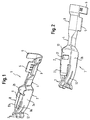
- Fig. 1 shows the socket contact 1 which has a base part 2 with two side faces 2a and 2b. Behind the base part 2 is a transition part 4, to which is connected the rear connection part 3.
- This connection part 3 consists of two crimping barrels 5 and 6 for a conductor wire (not shown) and for the conductor wire insulation.
- the guide rail 8 can consist of two parts, 8a and 8b, which are separated from one another by means of a slit 9.
- Fig. 2 shows the socket contact 1 seen diagonally from below.
- the base part 2 has a floor 10 at the front end of which is formed an extension 11.
- the side walls 2a and 2b, the floor 10 and the guide rail 8 form the four side walls of the base part.
- a recess 17 in which a box spring 13 shown in Fig. 3 can be secured to the socket contact.
- Each spring arm 7 can be divided into two single spring arms by means of a channel 12, so that when a contact pin (not shown) is introduced, a total of four contact faces results.
- Fig. 3 shows the box spring 13 inserted on the socket contact 1.
- two links 14 On the end of the box spring 13 are located two links 14 whose front ends are bent inwards.
- two ends 15 are cut out and bent outwards.
- Fig. 4 shows in part-section the front part of the socket contact with the box spring.
- two free ends 18 grip into a channel 17 of the socket contact 1 in order to lock the box spring 13 over the socket contact 1.
- a support point 19 of the spring arms 7 forms on the box spring 13. If a contact pin is introduced into the socket contact, the pre-tensioned spring arms 7 are forced further apart, the support point 19 of the spring arms on the box spring shifts in the direction of the front opening of the socket contact and the spring arm shortens so that the perpendicular force acting on the contact pin rises.
- the introduction of the contact pin of a counterplug becomes easier, since the said contact pin is centered and guided not only by the spring arms, but also by the guide rail.
- An oblique introduction at any desired angle in relation to the plug axis is prevented by the guide rail according to the invention, whereby the complete socket contact and a possible box spring are better protected from deformation.
Landscapes
- Details Of Connecting Devices For Male And Female Coupling (AREA)
- Coupling Device And Connection With Printed Circuit (AREA)
- Connector Housings Or Holding Contact Members (AREA)
- Connecting Device With Holders (AREA)
Applications Claiming Priority (2)
| Application Number | Priority Date | Filing Date | Title |
|---|---|---|---|
| DE19944280 | 1999-09-15 | ||
| DE19944280A DE19944280C1 (de) | 1999-09-15 | 1999-09-15 | Elektrischer Buchsenkontakt mit Führungssteg |
Publications (2)
| Publication Number | Publication Date |
|---|---|
| EP1085609A1 true EP1085609A1 (fr) | 2001-03-21 |
| EP1085609B1 EP1085609B1 (fr) | 2004-02-04 |
Family
ID=7922162
Family Applications (1)
| Application Number | Title | Priority Date | Filing Date |
|---|---|---|---|
| EP00119427A Expired - Lifetime EP1085609B1 (fr) | 1999-09-15 | 2000-09-13 | Contact à douille électrique avec un rail de guidage |
Country Status (5)
| Country | Link |
|---|---|
| US (1) | US6402571B1 (fr) |
| EP (1) | EP1085609B1 (fr) |
| AT (1) | ATE259105T1 (fr) |
| DE (2) | DE19944280C1 (fr) |
| MX (1) | MXPA00008906A (fr) |
Cited By (2)
| Publication number | Priority date | Publication date | Assignee | Title |
|---|---|---|---|---|
| EP1411592A1 (fr) * | 2002-10-19 | 2004-04-21 | Robert Bosch Gmbh | Connecteur électrique avec la configuration d'un contact à douille avec une formation speciale des lamelles |
| CN109478736A (zh) * | 2016-07-06 | 2019-03-15 | 泰连公司 | 具有减少的法向力的端子 |
Families Citing this family (63)
| Publication number | Priority date | Publication date | Assignee | Title |
|---|---|---|---|---|
| DE10034862B4 (de) * | 2000-07-18 | 2009-06-25 | Lear Corp., Southfield | Elektrisches Kontaktelement |
| DE10129614B4 (de) * | 2001-06-20 | 2006-01-19 | Delphi Technologies, Inc., Troy | Elektrisches Anschlußelement |
| USD494545S1 (en) | 2002-05-27 | 2004-08-17 | J.S.T. Mfg. Co., Ltd. | Socket contact |
| ES2421432T3 (es) * | 2002-11-15 | 2013-09-02 | Tyco Electronics Amp Gmbh | Elemento de contacto con lengüeta de resorte |
| TW562308U (en) * | 2003-04-02 | 2003-11-11 | Hon Hai Prec Ind Co Ltd | Contact of electrical connector |
| DE10331229A1 (de) * | 2003-07-10 | 2005-01-27 | Robert Bosch Gmbh | Kontaktanordnung bei einer elektrischen Steckverbindung |
| TWD107162S1 (zh) * | 2004-06-11 | 2005-10-21 | 鴻海精密工業股份有限公司 | 電連接器端子 |
| DE10335196B3 (de) * | 2003-07-30 | 2005-04-07 | Yazaki Europe Ltd., Hemel Hempstead | Kontaktbuchse für einen Flachstecker |
| USD516039S1 (en) * | 2004-05-31 | 2006-02-28 | Hon Hai Precision Ind. Co., Ltd. | Contact for an electrical connector |
| TWD107158S1 (zh) * | 2004-06-04 | 2005-10-21 | 鴻海精密工業股份有限公司 | 電連接器端子 |
| TWD107159S1 (zh) * | 2004-06-04 | 2005-10-21 | 鴻海精密工業股份有限公司 | 電連接器端子 |
| USD516524S1 (en) * | 2004-12-20 | 2006-03-07 | Cheng Uei Precision Industry Co., Ltd. | Electrical connector contact |
| US7291046B2 (en) * | 2005-08-22 | 2007-11-06 | Illinois Tool Works Inc. | Electrical contact assembly |
| DE102005062879A1 (de) * | 2005-12-29 | 2007-07-05 | Robert Bosch Gmbh | Elektrische Steckvorrichtung |
| KR100729147B1 (ko) | 2006-06-22 | 2007-06-19 | 고려대학교 산학협력단 | 고감도 바이오센서 및 이를 포함하는 복합 바이오센서 |
| JP4152425B2 (ja) * | 2006-06-27 | 2008-09-17 | 日本圧着端子製造株式会社 | 電気コネクタ |
| US7604519B2 (en) * | 2007-05-10 | 2009-10-20 | Hon Hai Precision Ind. Co., Ltd. | Connector assembly with improved contacts |
| US7632126B1 (en) * | 2008-05-23 | 2009-12-15 | Tyco Electronics Corporation | High density circular interconnect with bayonet action |
| US8021200B2 (en) * | 2008-08-04 | 2011-09-20 | Tyco Electronics Corporation | Socket contact |
| US20100029146A1 (en) * | 2008-08-04 | 2010-02-04 | Tyco Electronics Corporation | Socket contact |
| US8616926B2 (en) * | 2009-08-17 | 2013-12-31 | Norman R. Byrne | Solid wire terminal |
| CN102834980A (zh) * | 2010-02-16 | 2012-12-19 | Ag地球物理学产品有限公司 | 用于抗震电连接器的电触头 |
| JP2012028076A (ja) * | 2010-07-21 | 2012-02-09 | Auto Network Gijutsu Kenkyusho:Kk | 電線付き端子金具およびその製造方法 |
| DE102012017949A1 (de) * | 2011-09-28 | 2013-03-28 | Sumitomo Wiring Systems, Ltd. | Anschlusspassstück |
| USD665360S1 (en) * | 2011-10-21 | 2012-08-14 | Fci Americas Technology Llc | Electrical terminal |
| WO2014014869A2 (fr) | 2012-07-16 | 2014-01-23 | Commscope, Inc. Of North Carolina | Connecteurs mâles-femelles équilibrés |
| EP2690716B1 (fr) * | 2012-07-24 | 2018-05-02 | Delphi Technologies, Inc. | Elément de raccordement électrique |
| US8992270B2 (en) * | 2012-09-26 | 2015-03-31 | Lear Corporation | Electrical terminal |
| WO2014063142A1 (fr) | 2012-10-19 | 2014-04-24 | Lear Corporation | Borne électrique |
| EP3005485B1 (fr) * | 2013-06-07 | 2018-01-03 | FCI Asia Pte. Ltd. | Connecteur pour cable |
| DE102014009208B4 (de) | 2013-06-21 | 2018-08-09 | Lear Corporation | Elektrische anschlussanordnung |
| US10230189B2 (en) | 2013-12-03 | 2019-03-12 | Amphenol Fci Asia Pte Ltd | Connector and pin receiving contact for such a connector |
| US9444205B2 (en) | 2014-03-25 | 2016-09-13 | Lear Corporation | Electric connector with contact protection |
| DE102014208772B4 (de) * | 2014-05-09 | 2018-03-08 | Robert Bosch Gmbh | Kontaktelement und Verfahren zur Herstellung einer Kontaktelement-Kabel-Anordnung |
| US10128602B2 (en) | 2014-05-13 | 2018-11-13 | Lear Corporation | Electric connector with a terminal interface |
| US9847591B2 (en) | 2014-07-22 | 2017-12-19 | Lear Corporation | Electric terminal assembly |
| US9583898B2 (en) * | 2014-12-30 | 2017-02-28 | Gibson Brands, Inc. | Multiple contact jack |
| CN107431299B (zh) | 2015-02-27 | 2019-05-21 | 诺曼·R·伯恩 | 用于汇流条和刀片端子的电触点接收器 |
| JP6075431B1 (ja) * | 2015-10-30 | 2017-02-08 | 第一精工株式会社 | コネクタ端子及びその製造方法 |
| GB2547958B (en) | 2016-03-04 | 2019-12-18 | Commscope Technologies Llc | Two-wire plug and receptacle |
| US9653859B1 (en) * | 2016-04-11 | 2017-05-16 | Delphi Technologies, Inc. | Electrical connector system |
| USD826863S1 (en) * | 2016-04-25 | 2018-08-28 | Phoenix Contact Gmbh & Co. Kg | Electrical connector |
| US9905953B1 (en) | 2016-09-30 | 2018-02-27 | Slobodan Pavlovic | High power spring-actuated electrical connector |
| CN106532314A (zh) * | 2016-11-17 | 2017-03-22 | 町洋机电(中国)有限公司 | 具有增加夹持力的夹片端子及插头电连接器 |
| CN115313081A (zh) | 2017-04-24 | 2022-11-08 | 康普技术有限责任公司 | 用于单个扭绞导体对的连接器 |
| WO2018227057A1 (fr) | 2017-06-08 | 2018-12-13 | Commscope Technologies Llc | Connecteurs pour une paire torsadée unique de conducteurs |
| US10468787B2 (en) | 2017-07-07 | 2019-11-05 | Avx Corporation | Wire-to-wire connector with integrated wire stop |
| WO2019147774A1 (fr) | 2018-01-26 | 2019-08-01 | Commscope Technologies Llc | Connecteurs pour paire torsadée unique de conducteurs |
| JP6989715B2 (ja) | 2018-02-26 | 2022-01-05 | ロイヤル プレシジョン プロダクツ,エルエルシー | 高電力用途用のばね作動式電気コネクター |
| CN111937243B (zh) | 2018-02-26 | 2022-07-15 | 康普技术有限责任公司 | 用于单绞合导线对的连接器和触头 |
| CN115986449A (zh) | 2018-03-16 | 2023-04-18 | 富加宜(美国)有限责任公司 | 高密度电连接器 |
| WO2019237009A1 (fr) | 2018-06-07 | 2019-12-12 | Royal Precision Products, Llc | Système de connecteur électrique avec composant ressort interne |
| CN108963510A (zh) * | 2018-07-05 | 2018-12-07 | 欧品电子(昆山)有限公司 | 高速连接器组件、插座连接器及其插座端子 |
| CN119108838A (zh) | 2019-01-15 | 2024-12-10 | 伊顿智能动力有限公司 | 带有内部弹簧部件的屏蔽电连接器系统 |
| CN113508498B (zh) | 2019-01-21 | 2025-03-18 | 皇家精密制品有限责任公司 | 汇流排系统 |
| CN113574748A (zh) | 2019-03-15 | 2021-10-29 | 康普技术有限责任公司 | 用于单绞合导线对的连接器和触头 |
| US11721942B2 (en) | 2019-09-09 | 2023-08-08 | Eaton Intelligent Power Limited | Connector system for a component in a power management system in a motor vehicle |
| DE112020003846T5 (de) | 2019-09-09 | 2022-05-12 | Royal Precision Products Llc | Verbinderaufzeichnungssystem mit lesbaren und aufzeichenbarenkennzeichnungen |
| US12316055B2 (en) | 2019-09-30 | 2025-05-27 | Commscope Technologies Llc | Couplers for single pair connectors |
| EP4038430A4 (fr) | 2019-09-30 | 2024-02-28 | CommScope Technologies LLC | Panneau de couplage à haute densité |
| CN113948896B (zh) * | 2020-07-15 | 2023-12-08 | 泰科电子(上海)有限公司 | 导电端子和连接器 |
| US11929572B2 (en) | 2020-07-29 | 2024-03-12 | Eaton Intelligent Power Limited | Connector system including an interlock system |
| US12199372B2 (en) | 2021-02-26 | 2025-01-14 | Commscope Technologies Llc | Couplers for single pair connectors |
Citations (4)
| Publication number | Priority date | Publication date | Assignee | Title |
|---|---|---|---|---|
| EP0189821A2 (fr) * | 1985-01-26 | 1986-08-06 | Delphi Automotive Systems Deutschland GmbH | Contact électrique à double ressort à lame |
| GB2228150A (en) * | 1989-01-24 | 1990-08-15 | Yazaki Corp | Device for interconnecting electrical terminals |
| EP0669678A1 (fr) * | 1989-02-24 | 1995-08-30 | Molex Incorporated | Connecteur électrique pour injecteur de combustible et ses bornes |
| US5616041A (en) * | 1995-01-17 | 1997-04-01 | Heyco Stamped Products, Inc. | Female connector for a plastic molded receptacle and an extension cord |
Family Cites Families (5)
| Publication number | Priority date | Publication date | Assignee | Title |
|---|---|---|---|---|
| FR2621180B1 (fr) * | 1987-09-28 | 1990-01-12 | Francelco Sa | Borne de contact electrique de type cage |
| DE9211819U1 (de) * | 1992-07-07 | 1993-11-04 | Grote & Hartmann | Elektrisches Kontaktelement |
| JP3535211B2 (ja) * | 1994-05-11 | 2004-06-07 | 矢崎総業株式会社 | 雌端子 |
| JP3216757B2 (ja) * | 1994-06-27 | 2001-10-09 | 矢崎総業株式会社 | 端 子 |
| DE19602822C2 (de) * | 1996-01-26 | 1998-02-19 | Siemens Ag | Kontaktfeder |
-
1999
- 1999-09-15 DE DE19944280A patent/DE19944280C1/de not_active Expired - Fee Related
-
2000
- 2000-09-12 MX MXPA00008906A patent/MXPA00008906A/es unknown
- 2000-09-13 AT AT00119427T patent/ATE259105T1/de not_active IP Right Cessation
- 2000-09-13 EP EP00119427A patent/EP1085609B1/fr not_active Expired - Lifetime
- 2000-09-13 DE DE60008052T patent/DE60008052D1/de not_active Expired - Lifetime
- 2000-09-14 US US09/661,953 patent/US6402571B1/en not_active Expired - Fee Related
Patent Citations (4)
| Publication number | Priority date | Publication date | Assignee | Title |
|---|---|---|---|---|
| EP0189821A2 (fr) * | 1985-01-26 | 1986-08-06 | Delphi Automotive Systems Deutschland GmbH | Contact électrique à double ressort à lame |
| GB2228150A (en) * | 1989-01-24 | 1990-08-15 | Yazaki Corp | Device for interconnecting electrical terminals |
| EP0669678A1 (fr) * | 1989-02-24 | 1995-08-30 | Molex Incorporated | Connecteur électrique pour injecteur de combustible et ses bornes |
| US5616041A (en) * | 1995-01-17 | 1997-04-01 | Heyco Stamped Products, Inc. | Female connector for a plastic molded receptacle and an extension cord |
Cited By (4)
| Publication number | Priority date | Publication date | Assignee | Title |
|---|---|---|---|---|
| EP1411592A1 (fr) * | 2002-10-19 | 2004-04-21 | Robert Bosch Gmbh | Connecteur électrique avec la configuration d'un contact à douille avec une formation speciale des lamelles |
| US7556542B2 (en) | 2002-10-19 | 2009-07-07 | Robert Bosch Gmbh | Electrical connector in the form of a socket contact having a special lamellar construction |
| CN109478736A (zh) * | 2016-07-06 | 2019-03-15 | 泰连公司 | 具有减少的法向力的端子 |
| CN109478736B (zh) * | 2016-07-06 | 2020-07-28 | 泰连公司 | 具有减少的法向力的端子 |
Also Published As
| Publication number | Publication date |
|---|---|
| MXPA00008906A (es) | 2002-04-24 |
| DE19944280C1 (de) | 2001-02-01 |
| EP1085609B1 (fr) | 2004-02-04 |
| ATE259105T1 (de) | 2004-02-15 |
| DE60008052D1 (de) | 2004-03-11 |
| US6402571B1 (en) | 2002-06-11 |
Similar Documents
| Publication | Publication Date | Title |
|---|---|---|
| EP1085609B1 (fr) | Contact à douille électrique avec un rail de guidage | |
| EP0818855B1 (fr) | Connecteur | |
| EP1120861B1 (fr) | Connecteur électrique avec contact femelle amélioré | |
| EP1215765B1 (fr) | Borne femelle à sertir | |
| US4906212A (en) | Electrical pin and socket connector | |
| EP1313174B1 (fr) | Borne femelle et connecteur électrique comportant cette borne | |
| JPH07296886A (ja) | リセプタクル端子 | |
| JPS6343275A (ja) | 接触ソケット | |
| EP3096409B1 (fr) | Contact pour connecteurs électriques | |
| EP0390889B1 (fr) | Connecteur electrique | |
| KR102653981B1 (ko) | 쌍의 압착편을 갖는 하우징을 구비한 동축 케이블 커넥터 | |
| US10468802B2 (en) | Terminal connecting structure | |
| US20100130075A1 (en) | Female Electrical Contact Comprising Spring Contact Plates | |
| US20060264124A1 (en) | Sleeveless stamped and formed socket contact | |
| CA1101094A (fr) | Traduction non-disponible | |
| US7654865B2 (en) | Electrical connector | |
| EP0937318B1 (fr) | Borne femelle dotee d'un manchon protecteur | |
| JP3221557B2 (ja) | 電気コンタクト | |
| US7556530B2 (en) | Connector in which defective electrical connection between a plurality of shell components is suppressed | |
| JPH03145081A (ja) | 低挿入力の電気コネクタ | |
| JP2782437B2 (ja) | 電気接触端子 | |
| KR102290435B1 (ko) | 밴드케이블 | |
| JP3358153B2 (ja) | 可動接続体 | |
| US5616048A (en) | Electrical connector with electrical contact and strain relief | |
| US20050042935A1 (en) | Solderless electrical contact |
Legal Events
| Date | Code | Title | Description |
|---|---|---|---|
| PUAI | Public reference made under article 153(3) epc to a published international application that has entered the european phase |
Free format text: ORIGINAL CODE: 0009012 |
|
| AK | Designated contracting states |
Kind code of ref document: A1 Designated state(s): AT BE CH CY DE DK ES FI FR GB GR IE IT LI LU MC NL PT SE |
|
| AX | Request for extension of the european patent |
Free format text: AL;LT;LV;MK;RO;SI |
|
| 17P | Request for examination filed |
Effective date: 20010911 |
|
| AKX | Designation fees paid |
Free format text: AT BE CH CY DE DK ES FI FR GB GR IE IT LI LU MC NL PT SE |
|
| 17Q | First examination report despatched |
Effective date: 20020128 |
|
| GRAH | Despatch of communication of intention to grant a patent |
Free format text: ORIGINAL CODE: EPIDOS IGRA |
|
| GRAH | Despatch of communication of intention to grant a patent |
Free format text: ORIGINAL CODE: EPIDOS IGRA |
|
| RAP1 | Party data changed (applicant data changed or rights of an application transferred) |
Owner name: FCI |
|
| RAP1 | Party data changed (applicant data changed or rights of an application transferred) |
Owner name: FCI |
|
| GRAA | (expected) grant |
Free format text: ORIGINAL CODE: 0009210 |
|
| AK | Designated contracting states |
Kind code of ref document: B1 Designated state(s): AT BE CH CY DE DK ES FI FR GB GR IE IT LI LU MC NL PT SE |
|
| PG25 | Lapsed in a contracting state [announced via postgrant information from national office to epo] |
Ref country code: FI Free format text: LAPSE BECAUSE OF FAILURE TO SUBMIT A TRANSLATION OF THE DESCRIPTION OR TO PAY THE FEE WITHIN THE PRESCRIBED TIME-LIMIT Effective date: 20040204 Ref country code: BE Free format text: LAPSE BECAUSE OF FAILURE TO SUBMIT A TRANSLATION OF THE DESCRIPTION OR TO PAY THE FEE WITHIN THE PRESCRIBED TIME-LIMIT Effective date: 20040204 Ref country code: LI Free format text: LAPSE BECAUSE OF FAILURE TO SUBMIT A TRANSLATION OF THE DESCRIPTION OR TO PAY THE FEE WITHIN THE PRESCRIBED TIME-LIMIT Effective date: 20040204 Ref country code: CY Free format text: LAPSE BECAUSE OF FAILURE TO SUBMIT A TRANSLATION OF THE DESCRIPTION OR TO PAY THE FEE WITHIN THE PRESCRIBED TIME-LIMIT Effective date: 20040204 Ref country code: NL Free format text: LAPSE BECAUSE OF FAILURE TO SUBMIT A TRANSLATION OF THE DESCRIPTION OR TO PAY THE FEE WITHIN THE PRESCRIBED TIME-LIMIT Effective date: 20040204 Ref country code: AT Free format text: LAPSE BECAUSE OF FAILURE TO SUBMIT A TRANSLATION OF THE DESCRIPTION OR TO PAY THE FEE WITHIN THE PRESCRIBED TIME-LIMIT Effective date: 20040204 Ref country code: CH Free format text: LAPSE BECAUSE OF FAILURE TO SUBMIT A TRANSLATION OF THE DESCRIPTION OR TO PAY THE FEE WITHIN THE PRESCRIBED TIME-LIMIT Effective date: 20040204 |
|
| REG | Reference to a national code |
Ref country code: GB Ref legal event code: FG4D |
|
| REG | Reference to a national code |
Ref country code: CH Ref legal event code: EP |
|
| REG | Reference to a national code |
Ref country code: IE Ref legal event code: FG4D |
|
| REF | Corresponds to: |
Ref document number: 60008052 Country of ref document: DE Date of ref document: 20040311 Kind code of ref document: P |
|
| PG25 | Lapsed in a contracting state [announced via postgrant information from national office to epo] |
Ref country code: GR Free format text: LAPSE BECAUSE OF FAILURE TO SUBMIT A TRANSLATION OF THE DESCRIPTION OR TO PAY THE FEE WITHIN THE PRESCRIBED TIME-LIMIT Effective date: 20040504 Ref country code: SE Free format text: LAPSE BECAUSE OF FAILURE TO SUBMIT A TRANSLATION OF THE DESCRIPTION OR TO PAY THE FEE WITHIN THE PRESCRIBED TIME-LIMIT Effective date: 20040504 Ref country code: DK Free format text: LAPSE BECAUSE OF FAILURE TO SUBMIT A TRANSLATION OF THE DESCRIPTION OR TO PAY THE FEE WITHIN THE PRESCRIBED TIME-LIMIT Effective date: 20040504 |
|
| PG25 | Lapsed in a contracting state [announced via postgrant information from national office to epo] |
Ref country code: DE Free format text: LAPSE BECAUSE OF FAILURE TO SUBMIT A TRANSLATION OF THE DESCRIPTION OR TO PAY THE FEE WITHIN THE PRESCRIBED TIME-LIMIT Effective date: 20040505 |
|
| PG25 | Lapsed in a contracting state [announced via postgrant information from national office to epo] |
Ref country code: ES Free format text: LAPSE BECAUSE OF FAILURE TO SUBMIT A TRANSLATION OF THE DESCRIPTION OR TO PAY THE FEE WITHIN THE PRESCRIBED TIME-LIMIT Effective date: 20040515 |
|
| NLV1 | Nl: lapsed or annulled due to failure to fulfill the requirements of art. 29p and 29m of the patents act | ||
| REG | Reference to a national code |
Ref country code: CH Ref legal event code: PL |
|
| PG25 | Lapsed in a contracting state [announced via postgrant information from national office to epo] |
Ref country code: IE Free format text: LAPSE BECAUSE OF NON-PAYMENT OF DUE FEES Effective date: 20040913 Ref country code: LU Free format text: LAPSE BECAUSE OF NON-PAYMENT OF DUE FEES Effective date: 20040913 |
|
| PG25 | Lapsed in a contracting state [announced via postgrant information from national office to epo] |
Ref country code: MC Free format text: LAPSE BECAUSE OF NON-PAYMENT OF DUE FEES Effective date: 20040930 |
|
| ET | Fr: translation filed | ||
| PLBE | No opposition filed within time limit |
Free format text: ORIGINAL CODE: 0009261 |
|
| STAA | Information on the status of an ep patent application or granted ep patent |
Free format text: STATUS: NO OPPOSITION FILED WITHIN TIME LIMIT |
|
| REG | Reference to a national code |
Ref country code: FR Ref legal event code: CA |
|
| 26N | No opposition filed |
Effective date: 20041105 |
|
| REG | Reference to a national code |
Ref country code: IE Ref legal event code: MM4A |
|
| PG25 | Lapsed in a contracting state [announced via postgrant information from national office to epo] |
Ref country code: PT Free format text: LAPSE BECAUSE OF NON-PAYMENT OF DUE FEES Effective date: 20040704 |
|
| PGFP | Annual fee paid to national office [announced via postgrant information from national office to epo] |
Ref country code: GB Payment date: 20070809 Year of fee payment: 8 |
|
| GBPC | Gb: european patent ceased through non-payment of renewal fee |
Effective date: 20080913 |
|
| PG25 | Lapsed in a contracting state [announced via postgrant information from national office to epo] |
Ref country code: GB Free format text: LAPSE BECAUSE OF NON-PAYMENT OF DUE FEES Effective date: 20080913 |
|
| PGFP | Annual fee paid to national office [announced via postgrant information from national office to epo] |
Ref country code: IT Payment date: 20090917 Year of fee payment: 10 |
|
| PG25 | Lapsed in a contracting state [announced via postgrant information from national office to epo] |
Ref country code: IT Free format text: LAPSE BECAUSE OF NON-PAYMENT OF DUE FEES Effective date: 20100913 |
|
| REG | Reference to a national code |
Ref country code: FR Ref legal event code: ST Effective date: 20110531 |
|
| PG25 | Lapsed in a contracting state [announced via postgrant information from national office to epo] |
Ref country code: FR Free format text: LAPSE BECAUSE OF NON-PAYMENT OF DUE FEES Effective date: 20100930 |
|
| PGFP | Annual fee paid to national office [announced via postgrant information from national office to epo] |
Ref country code: FR Payment date: 20090916 Year of fee payment: 10 |