EP1085641A1 - Dispositif d'entraínement d'un élément positionneur - Google Patents
Dispositif d'entraínement d'un élément positionneur Download PDFInfo
- Publication number
- EP1085641A1 EP1085641A1 EP99118212A EP99118212A EP1085641A1 EP 1085641 A1 EP1085641 A1 EP 1085641A1 EP 99118212 A EP99118212 A EP 99118212A EP 99118212 A EP99118212 A EP 99118212A EP 1085641 A1 EP1085641 A1 EP 1085641A1
- Authority
- EP
- European Patent Office
- Prior art keywords
- spring
- auxiliary spring
- actuator
- auxiliary
- drive device
- Prior art date
- Legal status (The legal status is an assumption and is not a legal conclusion. Google has not performed a legal analysis and makes no representation as to the accuracy of the status listed.)
- Withdrawn
Links
Images

Classifications
-
- H—ELECTRICITY
- H02—GENERATION; CONVERSION OR DISTRIBUTION OF ELECTRIC POWER
- H02K—DYNAMO-ELECTRIC MACHINES
- H02K7/00—Arrangements for handling mechanical energy structurally associated with dynamo-electric machines, e.g. structural association with mechanical driving motors or auxiliary dynamo-electric machines
- H02K7/10—Structural association with clutches, brakes, gears, pulleys or mechanical starters
- H02K7/108—Structural association with clutches, brakes, gears, pulleys or mechanical starters with friction clutches
-
- F—MECHANICAL ENGINEERING; LIGHTING; HEATING; WEAPONS; BLASTING
- F16—ENGINEERING ELEMENTS AND UNITS; GENERAL MEASURES FOR PRODUCING AND MAINTAINING EFFECTIVE FUNCTIONING OF MACHINES OR INSTALLATIONS; THERMAL INSULATION IN GENERAL
- F16D—COUPLINGS FOR TRANSMITTING ROTATION; CLUTCHES; BRAKES
- F16D7/00—Slip couplings, e.g. slipping on overload, for absorbing shock
- F16D7/02—Slip couplings, e.g. slipping on overload, for absorbing shock of the friction type
- F16D7/022—Slip couplings, e.g. slipping on overload, for absorbing shock of the friction type with a helical band or equivalent member co-operating with a cylindrical torque limiting coupling surface
-
- H—ELECTRICITY
- H02—GENERATION; CONVERSION OR DISTRIBUTION OF ELECTRIC POWER
- H02K—DYNAMO-ELECTRIC MACHINES
- H02K7/00—Arrangements for handling mechanical energy structurally associated with dynamo-electric machines, e.g. structural association with mechanical driving motors or auxiliary dynamo-electric machines
- H02K7/10—Structural association with clutches, brakes, gears, pulleys or mechanical starters
- H02K7/118—Structural association with clutches, brakes, gears, pulleys or mechanical starters with starting devices
Definitions
- the invention relates to a drive device according to the preamble of Claim 1.
- Such drive devices are advantageous in heating, ventilation and air conditioning systems Actuation of actuators such as flaps, valves or slides and the like is used.
- a drive device of the type mentioned in the preamble of claim 1 is known from DE 195 16 973 A1 known.
- the known drive device has a return spring and also an auxiliary spring for overcoming a holding torque and a cogging torque of Gearbox and electromagnetic drive motor.
- the return spring has in the event of a power failure to apply a torque required to actuate an actuator.
- the return spring can be designed for a relatively small torque saving space, material and costs.
- the auxiliary spring also has the function of Overrunning clutch, by which damage, in particular to the gearbox, can be prevented if the actuator reaches the predetermined safety position in the event of a power failure, since the rotating Flywheel mass of the drive motor via the auxiliary spring acting as a one-way clutch up to Standstill is leakable.
- wrap spring clutches are, for example EP 678 685 A1, from US 3 125 889, from US 3 893 554, from EP 463 248 A1 and US 4 630 722 known.
- the known drive device has the disadvantage that in addition to the auxiliary spring and Free-wheel clutch wrap spring additionally an overload clutch to prevent damage to the gearbox is necessary.
- the overload clutch is used when the actuator reaches a certain end position and the drive motor continues the actuator drives against an attack.
- the invention has for its object to propose a drive device which has a simpler structure without losing functionality and reliability.
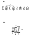
- Fig. 1, 1 means an actuator, which between two via a drive device End positions can be actuated. If the actuator 1 is, for example, an air flap, it has a first one End position the maximum passage opening and a second end position the minimum Passage opening result, the minimum passage opening usually a complete closed air flap means.
- the actuator 1 is, for example, an air flap, it has a first one End position the maximum passage opening and a second end position the minimum Passage opening result, the minimum passage opening usually a complete closed air flap means.
- the drive device has an electric motor 2, gear stages 3 and 4 and one Advantage between the gear stages 3 and 4 arranged return spring 5.
- the Return spring 5 is an energy store, by the energy of which the actuator 1 in the event of a failure of the electrical supply network can be positioned in a predetermined safety position.
- the safety position corresponds to one of the two end positions of the actuator 1 and is in the Usually configurable.
- An auxiliary spring 6 is arranged between the electric motor 2 and a first gear stage 3, the auxiliary spring 6 in an advantageous manner on the one hand via a first coil spring coupling 7 with the electric motor 2 and on the other hand via a second coil spring clutch 8 with the Gear stage 3 is connected.
- the auxiliary spring 6 has free windings for generating a drive shock through which as is known, in particular torque levels of gear stage 3, but also a magnetic one Detent torque of the electric motor 2 can be overcome.
- the two coil spring clutches 7 and 8 are in the direction of rotation of the electric motor 2 coordinated and designed such that one of the two coil spring couplings 7 or 8 as Overrunning clutch is effective when the actuator 1 has the predetermined safety position reached and the other of the two coil spring clutches 7 or 8 as an overload clutch becomes effective when the actuator 1 reaches a further predetermined position.
- the auxiliary spring 6 is a second stage of an advantageously three-stage executed spring element 10.
- a first end 11 of several turns Auxiliary spring 6 is the first stage and a second end 12 having several turns Auxiliary spring is designed as the third stage of the spring element 10.
- the first stage of the spring element 10 is designed in this way and around an axis of rotation 13 rotatably arranged body that the first end 11 together with the body as a loopable Wrap spring clutch works.
- the third stage of the spring element 10, however, is such executed and in an axially lying in the axis of rotation 13 bore of another rotatable Body usable that the second end 12 together with the wider body Spreading spring clutch works.
- the spring element 10 is wound in one piece in a winding direction, the cross section of the the material used for winding is selected to be rectangular or round, depending on the requirements.
- the winding diameter of the three - advantageously cylindrical - wound and stages 11, 6 and 12 arranged one behind the other are advantageously different from one another, the first stage 11, which can be coupled as a wrap spring, advantageously the smallest Has winding diameter, and the third stage 12, which can be coupled as an expansion spring advantageously has the largest winding diameter. Because the Winding diameter of the auxiliary spring 6 different from the winding diameter of the first Stage 11 and also different from the winding diameter of the third stage 12 are Signs of wear on the spring element and on those coupled to the spring element 10 Bodies can be minimized.
- auxiliary spring 6 is only partially shown for the sake of clarity Drive device 15 arranged.
- the first end 11 is wound around a hub 16 which is firmly connected to a drive shaft 17 of the electric motor 2.
- the second end 12 is like this arranged in a recess 18 of a drum 19 that the winding from the inside to a Outer wall 20 of the drum 19 abuts.
- the first coil spring clutch 7 is by the Hub 16 and the first end 11 realized while the second coil spring clutch 8 is realized by the second end 12 and the drum 19.
- the torque that can be transmitted by the first coil spring clutch 7 can be selected of the outer diameter of the hub 16 is defined within wide limits in accordance with the requirements become. It goes without saying that the spring element 10 in one embodiment variant of the Coil spring clutch 7 can be looped directly around the drive axis 17.
- the drum 19 is completed by a pinion 21, which is part of the Gear stage 3 (Fig. 1).
- 25 denotes one of one Supply network powered voltage source, the energy of which the electric motor 2 in one normal operating state of the drive device 15 can be driven.
- one Return spring has the embodiment an electrical energy storage 26.
- the in Electrical energy storage 26 stored energy is dimensioned so that it is sufficient to Actuator 1 in the event of a failure of the electrical supply network via the electric motor to position the predetermined safety position.
- the electrical energy store 26 is, for example, a battery, an accumulator or a Capacitor.
- the variant requires a circuit through which a power failure occurs detectable and positioning in the safety position can be initiated.
- the two coil spring clutches 7 and 8 are in the direction of rotation of the electric motor 2 coordinated and designed such that one of the two coil spring couplings 7 or 8 as Overrunning clutch is effective when the actuator 1 has the predetermined safety position reached and the other of the two coil spring clutches 7 or 8 as an overload clutch becomes effective when the actuator 1 reaches a further predetermined position.
Landscapes
- Engineering & Computer Science (AREA)
- General Engineering & Computer Science (AREA)
- Power Engineering (AREA)
- Mechanical Engineering (AREA)
- Mechanical Operated Clutches (AREA)
Priority Applications (1)
| Application Number | Priority Date | Filing Date | Title |
|---|---|---|---|
| EP99118212A EP1085641A1 (fr) | 1999-09-14 | 1999-09-14 | Dispositif d'entraínement d'un élément positionneur |
Applications Claiming Priority (1)
| Application Number | Priority Date | Filing Date | Title |
|---|---|---|---|
| EP99118212A EP1085641A1 (fr) | 1999-09-14 | 1999-09-14 | Dispositif d'entraínement d'un élément positionneur |
Publications (1)
| Publication Number | Publication Date |
|---|---|
| EP1085641A1 true EP1085641A1 (fr) | 2001-03-21 |
Family
ID=8238996
Family Applications (1)
| Application Number | Title | Priority Date | Filing Date |
|---|---|---|---|
| EP99118212A Withdrawn EP1085641A1 (fr) | 1999-09-14 | 1999-09-14 | Dispositif d'entraínement d'un élément positionneur |
Country Status (1)
| Country | Link |
|---|---|
| EP (1) | EP1085641A1 (fr) |
Cited By (1)
| Publication number | Priority date | Publication date | Assignee | Title |
|---|---|---|---|---|
| DE10303235B4 (de) * | 2002-01-29 | 2011-03-31 | Makita Corp., Anjo | Drehmomentübertragungsmechanismen und Motorwerkzeuge mit solchen Drehmomentübertragungsmechanismen |
Citations (3)
| Publication number | Priority date | Publication date | Assignee | Title |
|---|---|---|---|---|
| US3153352A (en) * | 1962-12-19 | 1964-10-20 | Curtiss Wright Corp | Automatically actuated spring clutches |
| US4465950A (en) * | 1981-08-19 | 1984-08-14 | Sodeco-Saia Sa | Synchron motor |
| US4763764A (en) * | 1987-06-12 | 1988-08-16 | General Motors Corporation | Wrapped spring, overrunning clutch assembly |
-
1999
- 1999-09-14 EP EP99118212A patent/EP1085641A1/fr not_active Withdrawn
Patent Citations (3)
| Publication number | Priority date | Publication date | Assignee | Title |
|---|---|---|---|---|
| US3153352A (en) * | 1962-12-19 | 1964-10-20 | Curtiss Wright Corp | Automatically actuated spring clutches |
| US4465950A (en) * | 1981-08-19 | 1984-08-14 | Sodeco-Saia Sa | Synchron motor |
| US4763764A (en) * | 1987-06-12 | 1988-08-16 | General Motors Corporation | Wrapped spring, overrunning clutch assembly |
Cited By (1)
| Publication number | Priority date | Publication date | Assignee | Title |
|---|---|---|---|---|
| DE10303235B4 (de) * | 2002-01-29 | 2011-03-31 | Makita Corp., Anjo | Drehmomentübertragungsmechanismen und Motorwerkzeuge mit solchen Drehmomentübertragungsmechanismen |
Similar Documents
| Publication | Publication Date | Title |
|---|---|---|
| DE102012025096B4 (de) | Antriebseinheit mit Energiespeichereinrichtung | |
| DE69228634T2 (de) | Getriebe eines elektrisch angetriebenen Werkzeuges | |
| DE112007002049B4 (de) | Feder-Rückstellventil mit Betätigungseinrichtung | |
| DE60305478T2 (de) | Vorrichtung zur einstellung einer rotorschaufel einer windenergieturbine | |
| EP1404956B1 (fr) | Mecanisme de commande a moteur electrique, muni d'une vis sans fin | |
| EP0865977A1 (fr) | Frein à disque actionné par un moteur électrique | |
| DE3843398A1 (de) | Betaetigungsvorrichtung fuer ein motorbetriebenes ventil | |
| EP0193776B1 (fr) | Valve pour arrêter un écoulement | |
| EP3308082A1 (fr) | Servomécanisme | |
| DE102018202922A1 (de) | Stelleinrichtung | |
| WO2001086371A1 (fr) | Dispositif d'actionnement | |
| DE102010063964A1 (de) | Eintreibgerät | |
| EP2193286A1 (fr) | Système d'entraînement à moteur d'une broche à sécurité anti-surcharge | |
| DE102022101840A1 (de) | Elektromechanischer Betätigungsaktor und Verfahren zum Betreiben eines elektromechanischen Betätigungsaktors | |
| DE102007007468A1 (de) | Kupplungsaktuatorik mit einem Generator und Kupplung mit einer solchen Kupplungsaktuatorik | |
| EP2536968B1 (fr) | Mécanisme de commande pour soupapes de sûreté à couple de commande élevé | |
| DE19516973B4 (de) | Antriebsvorrichtung für ein Stellglied | |
| DE60124308T2 (de) | Federbremsstellglied | |
| DE102007014831A1 (de) | Kupplungsaktuatorik mit einer Unterstützungseinrichtung und Kupplung mit einer solchen Kupplungsaktuatorik | |
| DE60218210T2 (de) | Klauenkupplungsvorrichtung | |
| DE102012205995A1 (de) | Schräg verzahntes Getriebe, elektrische Maschine | |
| DE20209356U1 (de) | Getriebe für Elektrowerkzeuge | |
| DE102008052843B4 (de) | Antriebseinheit für Verstelleinrichtungen in Kraftfahrzeugen | |
| DE102010041413A1 (de) | Linearer Stellantrieb mit einer rotativ angetriebenen Welle | |
| DE102004030005B4 (de) | Elektromechanischer Kupplungsaktuator für ein Fahrzeug mit einem automatisierten oder teilautomatisierten Schaltgetriebe |
Legal Events
| Date | Code | Title | Description |
|---|---|---|---|
| PUAI | Public reference made under article 153(3) epc to a published international application that has entered the european phase |
Free format text: ORIGINAL CODE: 0009012 |
|
| AK | Designated contracting states |
Kind code of ref document: A1 Designated state(s): AT BE CH CY DE DK ES FI FR GB GR IE IT LI LU MC NL PT SE |
|
| AX | Request for extension of the european patent |
Free format text: AL;LT;LV;MK;RO;SI |
|
| AKX | Designation fees paid | ||
| STAA | Information on the status of an ep patent application or granted ep patent |
Free format text: STATUS: THE APPLICATION IS DEEMED TO BE WITHDRAWN |
|
| 18D | Application deemed to be withdrawn |
Effective date: 20010922 |
|
| REG | Reference to a national code |
Ref country code: DE Ref legal event code: 8566 |