EP1085703A2 - Procédé de gestion de bus - Google Patents
Procédé de gestion de bus Download PDFInfo
- Publication number
- EP1085703A2 EP1085703A2 EP00203839A EP00203839A EP1085703A2 EP 1085703 A2 EP1085703 A2 EP 1085703A2 EP 00203839 A EP00203839 A EP 00203839A EP 00203839 A EP00203839 A EP 00203839A EP 1085703 A2 EP1085703 A2 EP 1085703A2
- Authority
- EP
- European Patent Office
- Prior art keywords
- bus
- node
- synchronous communication
- state information
- management node
- Prior art date
- Legal status (The legal status is an assumption and is not a legal conclusion. Google has not performed a legal analysis and makes no representation as to the accuracy of the status listed.)
- Withdrawn
Links
Images



Classifications
-
- H—ELECTRICITY
- H04—ELECTRIC COMMUNICATION TECHNIQUE
- H04L—TRANSMISSION OF DIGITAL INFORMATION, e.g. TELEGRAPHIC COMMUNICATION
- H04L12/00—Data switching networks
- H04L12/28—Data switching networks characterised by path configuration, e.g. LAN [Local Area Networks] or WAN [Wide Area Networks]
- H04L12/40—Bus networks
-
- H—ELECTRICITY
- H04—ELECTRIC COMMUNICATION TECHNIQUE
- H04L—TRANSMISSION OF DIGITAL INFORMATION, e.g. TELEGRAPHIC COMMUNICATION
- H04L12/00—Data switching networks
- H04L12/28—Data switching networks characterised by path configuration, e.g. LAN [Local Area Networks] or WAN [Wide Area Networks]
- H04L12/40—Bus networks
- H04L12/407—Bus networks with decentralised control
-
- H—ELECTRICITY
- H04—ELECTRIC COMMUNICATION TECHNIQUE
- H04L—TRANSMISSION OF DIGITAL INFORMATION, e.g. TELEGRAPHIC COMMUNICATION
- H04L12/00—Data switching networks
- H04L12/28—Data switching networks characterised by path configuration, e.g. LAN [Local Area Networks] or WAN [Wide Area Networks]
- H04L12/40—Bus networks
- H04L12/40006—Architecture of a communication node
- H04L12/40013—Details regarding a bus controller
-
- H—ELECTRICITY
- H04—ELECTRIC COMMUNICATION TECHNIQUE
- H04L—TRANSMISSION OF DIGITAL INFORMATION, e.g. TELEGRAPHIC COMMUNICATION
- H04L12/00—Data switching networks
- H04L12/28—Data switching networks characterised by path configuration, e.g. LAN [Local Area Networks] or WAN [Wide Area Networks]
- H04L12/40—Bus networks
- H04L12/40006—Architecture of a communication node
- H04L12/40032—Details regarding a bus interface enhancer
-
- H—ELECTRICITY
- H04—ELECTRIC COMMUNICATION TECHNIQUE
- H04L—TRANSMISSION OF DIGITAL INFORMATION, e.g. TELEGRAPHIC COMMUNICATION
- H04L12/00—Data switching networks
- H04L12/28—Data switching networks characterised by path configuration, e.g. LAN [Local Area Networks] or WAN [Wide Area Networks]
- H04L12/40—Bus networks
- H04L12/40052—High-speed IEEE 1394 serial bus
- H04L12/40058—Isochronous transmission
-
- H—ELECTRICITY
- H04—ELECTRIC COMMUNICATION TECHNIQUE
- H04L—TRANSMISSION OF DIGITAL INFORMATION, e.g. TELEGRAPHIC COMMUNICATION
- H04L12/00—Data switching networks
- H04L12/28—Data switching networks characterised by path configuration, e.g. LAN [Local Area Networks] or WAN [Wide Area Networks]
- H04L12/40—Bus networks
- H04L12/40052—High-speed IEEE 1394 serial bus
- H04L12/40065—Bandwidth and channel allocation
-
- H—ELECTRICITY
- H04—ELECTRIC COMMUNICATION TECHNIQUE
- H04L—TRANSMISSION OF DIGITAL INFORMATION, e.g. TELEGRAPHIC COMMUNICATION
- H04L12/00—Data switching networks
- H04L12/28—Data switching networks characterised by path configuration, e.g. LAN [Local Area Networks] or WAN [Wide Area Networks]
- H04L12/40—Bus networks
- H04L12/40052—High-speed IEEE 1394 serial bus
- H04L12/40117—Interconnection of audio or video/imaging devices
-
- H—ELECTRICITY
- H04—ELECTRIC COMMUNICATION TECHNIQUE
- H04L—TRANSMISSION OF DIGITAL INFORMATION, e.g. TELEGRAPHIC COMMUNICATION
- H04L12/00—Data switching networks
- H04L12/28—Data switching networks characterised by path configuration, e.g. LAN [Local Area Networks] or WAN [Wide Area Networks]
- H04L12/40—Bus networks
- H04L12/403—Bus networks with centralised control, e.g. polling
-
- H—ELECTRICITY
- H04—ELECTRIC COMMUNICATION TECHNIQUE
- H04L—TRANSMISSION OF DIGITAL INFORMATION, e.g. TELEGRAPHIC COMMUNICATION
- H04L12/00—Data switching networks
- H04L12/64—Hybrid switching systems
- H04L12/6418—Hybrid transport
-
- H—ELECTRICITY
- H04—ELECTRIC COMMUNICATION TECHNIQUE
- H04L—TRANSMISSION OF DIGITAL INFORMATION, e.g. TELEGRAPHIC COMMUNICATION
- H04L41/00—Arrangements for maintenance, administration or management of data switching networks, e.g. of packet switching networks
-
- H—ELECTRICITY
- H04—ELECTRIC COMMUNICATION TECHNIQUE
- H04L—TRANSMISSION OF DIGITAL INFORMATION, e.g. TELEGRAPHIC COMMUNICATION
- H04L12/00—Data switching networks
- H04L12/28—Data switching networks characterised by path configuration, e.g. LAN [Local Area Networks] or WAN [Wide Area Networks]
- H04L12/40—Bus networks
- H04L12/40052—High-speed IEEE 1394 serial bus
-
- H—ELECTRICITY
- H04—ELECTRIC COMMUNICATION TECHNIQUE
- H04L—TRANSMISSION OF DIGITAL INFORMATION, e.g. TELEGRAPHIC COMMUNICATION
- H04L12/00—Data switching networks
- H04L12/28—Data switching networks characterised by path configuration, e.g. LAN [Local Area Networks] or WAN [Wide Area Networks]
- H04L12/44—Star or tree networks
Definitions
- the node 21 permits an address to be accorded to the node 22.
- the node 22 accords the address (i) to itself and transmits data indicating that the address (i) has been accorded to itself over a bus 26.
- the node 21 then permits the node 23 to set its own address.
- the node 23 permits an address to be accorded to the node 24 connected to its port #1.
- the node 23 permits an address to be accorded to a node 25 connected to its port #2.
- the node 23 accords an address (iii) to itself. After having accorded addresses to its slave node 24 and slave node 25, the node 23 accords an address (iv) to itself. After having accorded addresses to its slave node 22 and slave node 23, the node 21 accords an address (v) to itself.
- communication is carried out at a communication cycle having a pre-set period, such as 125 ⁇ s, as shown in Fig.10.
- the communication cycle starts with a cycle start packet csp, followed by a period for transmitting a packet for synchronous communication.
- plural synchronous communication cycles may be carried out.
- the channel 1 is allocated to the communication from the node 22 to the node 23
- communication is carried, out by the node 22 transmitting the packet for synchronous communication having the channel number 1 directly after the cycle start packet csp and by the node 23 monitoring he bus 26 and fetching the packet for synchronous communication having the channel number 1.
- the communication from the node 24 to the node 21 can be accorded to the channel 2, while the packet of a channel can be received by plural nodes.
- the time interval until the next cycle start packet csp is employed for asynchronous communication.
- packets A and B in Fig.10 are affixed addresses of the transmitting node and the receiving node.
- the respective nodes fetch the packets having the addresses proper to the nodes affixed thereto.
- the bus management node checks if the communication capacity in use added to the communication capacity newly requested does not exceed the maximum communication capacity of the bus. If the sum is not in excess of the maximum communication capacity of the bus, the bus management node notices the channel number and the effect of permission of synchronous communication. If the sum is in excess of the maximum communication capacity of the bus, the bus management node notices that the channel allocation is not permitted. After termination of the synchronous communication, the management node is notified of the channel number and the channel capacity which will not be in use.
- the bus supervision is in need of complex processing operations, it is commonplace practice with the communication system centered about e.g., a personal computer to use the personal computer as a bus management node and to perform the processing operations using the software possessed by the personal computer.
- this method is employed for the communication system between the AV apparatus, such as a digital VTR, tuner or a monitor, it becomes necessary to interconnect an apparatus having powerful data processing functions, such as personal computer, to the bus, in addition to the AV apparatus, thus raising the cost of the communication system.
- the subject-matter of the claim 1 resides in a method for bus management in a system for performing synchronous communication between plural nodes connected to a bus in which, among the plural nodes, a pre-set node having first storage means for storing the channel use state and for storing the bus use state is set as a bus management node, each node reads out the contents of the first and second storage means when starting the synchronous communication, and in which, if there is any vacant channel or any vacant capacity, each node writes the number of the channel started to be used and the capacity of the bus started to be used in the first and second storage means, respectively.
- the channel number and the bus capacity may be supervised by the bus management node by simply responding to the readout command and the write command to the first and second storage means.
- each node ha plural communication clocks of different frequencies.
- each node to carry out communication by the communication clocks of plural different frequencies so that there can exist communication of different speeds from channel to channel.
- the subject-matter of claim 5 resides in the method for bus management as claimed in claim 2 wherein the bus use state stored in the second storage means has time-based values. Thus it becomes possible for the bus use state to have time-based values.
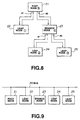
- the register for channels in use REG1 and the bus capacity register REG2 are provided in the respective nodes.
- the bus management node 11 is the node 21 as a root node. If the register for channels in use REG1 and the bus capacity register REG2 are provided in each of the respective nodes, bus management becomes possible no matter which node become the root node. Any node other than the root node may also be used as a bus management node.
- YES and NO in the decision steps are abbreviated to Y and N, respectively.
- the node 12 effecting the synchronous communication transmits to the bus management node 11 a command for reading out the contents of the register for channels in use REG1.
- the contents of the register for channels in use REG1 thus read out are checked in order to give judgement if there is any bit 0. If there is no 0 bit, there is no vacant channel, so that the processing comes to a close. If there ia a bit 0, the node 12 proceeds to step S2.
- the node 12 transmits a write command for resetting to 0 the bit set to 1 at step S2 to the bus management node 11.
- step S11 if the communication comes to a close at step S11, the node 12 proceeds to step S12, where the bit corresponding to the number of the channel of the register for channels in use REG1 which has ceased to be used is reset to 0.
- step S13 the node 12 adds the value of the capacity of the bus which has ceased to be used to the value of the register for channels in use REG1.
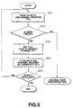
- Fig.5 is a flow chart for setting the bit of the register for channels in use REG1, that is the operations corresponding to the steps S1 and S2 of Fig.3.
- the node 12 reads the value (binary number) of the register for channels in use REG1 and sets the value to a .
- the node 12 then proceeds to step S22.
- the node 12 judges whether or not there is a bit 0 in a .
- the foregoing processing is substantially the same as the step S1 of Fig.3. If there is no bit 0 in a , the node 12 terminates the operational sequence of channel acquisition, since there is no vacant channel. If there is a bit 0 in a , the node 12 proceeds to step S23.
- the node 12 sets the value of the register REG1 in which the bit corresponding to the channel desired to be used for synchronous communication, is set to 1 to b , before proceeding to step S24.
- step S24 If at step S24 the value of the register for channels in use REG1 is a , the node 12 rewrites the value to b , before proceeding st step S25. That is, the processing at step S24 is the processing provided for evading the competition with other nodes.
- This step S24 can be implemented by a node desiring to occupy a channel transmitting a command to the bus management node 11 for rewriting the value of the register for channels in use REG1 from a to b .
- the value of the register for channels in use REG1 being a means that an other node has not rewritten the value of the register for channels in use REG1 since the time the node 12 read at step S21 the value of the register for channels in use REG1 until step S24. Conversely, the value of the register for channels in use REG1 not being a means that an other node has rewritten the value of the register for channels in use REG1.
- the node 12 judges whether or not the rewriting has resulted in success. If the result is YES, that is the rewriting has succeeded, the node 12 terminates the operating sequence. If otherwise, the node 12 returns to step S21.
- the decision as to the success/ failure may be given based on the notice of the results of writing transmitted from the bus management node 11, or by reading out the value of the register for channels in use REG1 and checking whether or not it has been rewritten to b .
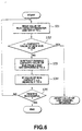
- the node 12 reads the value of the bus capacity register REG2 and set the value to c .
- the node 12 then proceeds to step S32 in which the node 12 judges which of c and the capacity value of the bus to be used newly is larger.
- the above processing is substantially the same as the step S3 shown in Fig.3. If c is smaller than the capacity value of the bus to be used newly, synchronous communication cannot be carried out, so the node 12 resets the value of the register for channels in use REG1 to its original value, as at step S6 shown in Fig.3. If c is larger than the capacity value of the bus to be used newly, synchronous communication can carried out, so the node 12 proceeds to step S33.
- step S34 is the processing for avoiding competition with other nodes.
- the value of the bus capacity register REG2 being c means that an other node has not rewritten the value of the bus capacity register REG2. since the time the node 12 has read out at step S31 the value of the bus capacity register REG2 until step S34.
- the value of the bus capacity register REG2 not being c means that an other node has rewritten the value of the bus capacity register REG2.
- step S35 the node judges whether or not rewriting has succeeded. If the rewriting has succeeded, the node 12 terminates the processing and, if otherwise, the node 12 returns to step S31.
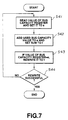
- Fig.7 is a flow chart showing the operating sequence of adding the bus capacity value to the value of the bus capacity register REG2, that is the operating sequence corresponding to the step S13 of Fig.4.
- step S41 the node 12 reads the value of the bus capacity register REG2, and sets it to e before proceeding to step S42.
- the node adds the capacity value of the bus whose end has come to a close to e and sets the sum to f before proceeding to step S43.
- each node in the communication system is capable of communication with the basic clocks of plural different frequencies, for example, 49.152 MHz, 2 ⁇ 49.152 MHz or 4 ⁇ 49.152 MHZ, and plural synchronous communication cycles are carried out at different basic clocks, it suffices to set the value stored in the bus capacity register REG2 so as to be equal to the value counted by a selected one of the plural basic clocks.
- the subject-matter of claim 1 provides a method for bus management in a system for performing synchronous communication between plural nodes connected to a bus, wherein, among the plural nodes, a pre-set node having first storage means for storing the channel use state and for storing the bus use state is set as a bus management node, each node reading out the contents of the first and second storage means when starting the synchronous communication. If there is any vacant channel or any vacant capacity, each node writes the number of the channel and the capacity of the bus started to be used in the first and second storage means, respectively. Since it is possible for the bus management node to manage the channel number and the bus capacity by simply responding to the readout command and the write command to the first storage means and to the second storage means, the method may be implemented by a simplified hardware.
- the subject-matter of claim 2 provides for an arrangement in which each node has plural communication clocks of different frequencies. Since the communication cycles with different plural frequencies can be caused to co-exist from channel to channel, it becomes possible to cope with data with different transmission rates, such as video data or audio data.
- the subject-matter of claim 3 provides for an arrangement in which, if the bus management node is changed within the preset time during the synchronous communication, the node already engaged in the synchronous communication executes the sequence of channel acquisition within a pre-set time. Consequently, channel allocation may be made preferentially to the node engaged in the synchronous communication before the bus management node is changed.
- the subject-matter of claim 4 provides for an arrangement in which the node having the maximum address is set to the bus management node, so that the bus management node may be automatically determined when the root node is set.
- the subject-matter of claim 5 provides for an arrangement in which the bus use state stored in the second storage means has time-based values, so that bus capacity management becomes possible even if the communication cycles with different rates co-exists from channel to channel.
Landscapes
- Engineering & Computer Science (AREA)
- Computer Networks & Wireless Communication (AREA)
- Signal Processing (AREA)
- Multimedia (AREA)
- Small-Scale Networks (AREA)
- Communication Control (AREA)
Applications Claiming Priority (3)
| Application Number | Priority Date | Filing Date | Title |
|---|---|---|---|
| JP20005593A JP3194318B2 (ja) | 1993-07-19 | 1993-07-19 | バス管理方法 |
| JP20005593 | 1993-07-19 | ||
| EP94921122A EP0674410B1 (fr) | 1993-07-19 | 1994-07-19 | Systeme de gestion de bus |
Related Parent Applications (1)
| Application Number | Title | Priority Date | Filing Date |
|---|---|---|---|
| EP94921122A Division EP0674410B1 (fr) | 1993-07-19 | 1994-07-19 | Systeme de gestion de bus |
Publications (2)
| Publication Number | Publication Date |
|---|---|
| EP1085703A2 true EP1085703A2 (fr) | 2001-03-21 |
| EP1085703A3 EP1085703A3 (fr) | 2006-05-10 |
Family
ID=16418088
Family Applications (5)
| Application Number | Title | Priority Date | Filing Date |
|---|---|---|---|
| EP94921122A Expired - Lifetime EP0674410B1 (fr) | 1993-07-19 | 1994-07-19 | Systeme de gestion de bus |
| EP00203840A Withdrawn EP1085704A3 (fr) | 1993-07-19 | 1994-07-19 | Procédé de gestion de bus |
| EP00203837A Withdrawn EP1085695A3 (fr) | 1993-07-19 | 1994-07-19 | Procédé de gestion pour un réseau en bus |
| EP00203838A Withdrawn EP1085702A3 (fr) | 1993-07-19 | 1994-07-19 | Procédé de gestion de bus |
| EP00203839A Withdrawn EP1085703A3 (fr) | 1993-07-19 | 1994-07-19 | Procédé de gestion de bus |
Family Applications Before (4)
| Application Number | Title | Priority Date | Filing Date |
|---|---|---|---|
| EP94921122A Expired - Lifetime EP0674410B1 (fr) | 1993-07-19 | 1994-07-19 | Systeme de gestion de bus |
| EP00203840A Withdrawn EP1085704A3 (fr) | 1993-07-19 | 1994-07-19 | Procédé de gestion de bus |
| EP00203837A Withdrawn EP1085695A3 (fr) | 1993-07-19 | 1994-07-19 | Procédé de gestion pour un réseau en bus |
| EP00203838A Withdrawn EP1085702A3 (fr) | 1993-07-19 | 1994-07-19 | Procédé de gestion de bus |
Country Status (8)
| Country | Link |
|---|---|
| US (6) | US5978360A (fr) |
| EP (5) | EP0674410B1 (fr) |
| JP (1) | JP3194318B2 (fr) |
| KR (1) | KR100295220B1 (fr) |
| CA (1) | CA2144970C (fr) |
| DE (1) | DE69429908T2 (fr) |
| TW (1) | TW445413B (fr) |
| WO (1) | WO1995003658A1 (fr) |
Families Citing this family (19)
| Publication number | Priority date | Publication date | Assignee | Title |
|---|---|---|---|---|
| JP3194318B2 (ja) * | 1993-07-19 | 2001-07-30 | ソニー株式会社 | バス管理方法 |
| JP3277694B2 (ja) * | 1994-05-25 | 2002-04-22 | ソニー株式会社 | 通信方法 |
| JP3249334B2 (ja) * | 1995-04-06 | 2002-01-21 | 株式会社東芝 | ディジタルインターフェース装置及びディジタルインターフェース方法 |
| US6577646B2 (en) | 1995-04-28 | 2003-06-10 | Matsushita Electric Industrial Co., Ltd. | Data transmitting apparatus, data receiving apparatus and data transmission control apparatus |
| DE69631182T2 (de) | 1995-04-28 | 2004-08-19 | Matsushita Electric Industrial Co., Ltd., Kadoma | Datenübertragungsverfahren |
| DE69634500T2 (de) * | 1995-06-15 | 2006-04-13 | Koninklijke Philips Electronics N.V. | Datenbussystem mit Mitteln zur Ressourcensteuerung und Übertragungsstation |
| JPH11168473A (ja) | 1997-12-04 | 1999-06-22 | Matsushita Electric Ind Co Ltd | シリアルバス管理装置 |
| JP3606423B2 (ja) * | 1998-05-21 | 2005-01-05 | 株式会社ケンウッド | Ieee1394シリアルバス装備avシステム |
| US6457077B1 (en) * | 1999-06-10 | 2002-09-24 | International Business Machines Corporation | System for executing a current information transfer request even when current information transfer request exceeds current available capacity of a transit buffer |
| JP2001045030A (ja) * | 1999-07-29 | 2001-02-16 | Nec Corp | 接続制御装置 |
| WO2001015384A2 (fr) * | 1999-08-20 | 2001-03-01 | Siemens Aktiengesellschaft | Systeme et procede pour la transmission d'informations entre deux interlocuteurs d'une communication par l'intermediaire d'un bus de terrain |
| DE10038155A1 (de) * | 2000-08-04 | 2002-02-21 | Siemens Ag | Kommunikationsverfahren |
| US6985979B2 (en) * | 2001-12-17 | 2006-01-10 | Matsushita Electric Industrial Co., Ltd. | Digital data processing device, bus controlling method, bus controlling program and recording medium |
| JP3739087B2 (ja) | 2002-03-15 | 2006-01-25 | 株式会社東芝 | Av機器及びその制御方法、av機器ネットワークシステム |
| US7457302B1 (en) * | 2002-12-31 | 2008-11-25 | Apple Inc. | Enhancement to loop healing for malconfigured bus prevention |
| US8246940B2 (en) * | 2003-11-18 | 2012-08-21 | L'oreal S.A. | Cosmetic composition comprising gellan gum or a derivative thereof, a fixing polymer, a monovalent salt and an alcohol, process of using the same |
| JP4315850B2 (ja) * | 2004-03-30 | 2009-08-19 | 富士通株式会社 | マルチキャストデータ通信システム、データ通信装置、マルチキャストデータ通信方法及びプログラム |
| JP4068592B2 (ja) * | 2004-05-28 | 2008-03-26 | 株式会社東芝 | 無線通信装置 |
| US20060212309A1 (en) * | 2005-03-18 | 2006-09-21 | Pitney Bowes Incorporated | Method for determining the best day of the week for a recipient to receive a mail piece |
Family Cites Families (22)
| Publication number | Priority date | Publication date | Assignee | Title |
|---|---|---|---|---|
| US3851104A (en) * | 1973-04-11 | 1974-11-26 | Mitre Corp | Digital communications system |
| US4495564A (en) * | 1981-08-10 | 1985-01-22 | International Business Machines Corporation | Multi sub-channel adapter with single status/address register |
| DE3580481D1 (de) * | 1985-08-13 | 1990-12-13 | Ibm | Mechanismus zur dynamischen zuordnung von bandbreite zwischen durchschaltkanaelen und paketbitstrom in einem nachrichtennetz. |
| US5119710A (en) * | 1986-03-09 | 1992-06-09 | Nippon Gakki Seizo Kabushiki Kaisha | Musical tone generator |
| US4763319A (en) * | 1986-05-19 | 1988-08-09 | Bell Communications Research, Inc. | Multi-rate synchronous virtual circuit network for voice and data communications |
| JPS63157203A (ja) * | 1986-12-20 | 1988-06-30 | Fujitsu General Ltd | Avシステム |
| US4988990A (en) * | 1989-05-09 | 1991-01-29 | Rosemount Inc. | Dual master implied token communication system |
| DE3736081A1 (de) * | 1987-10-24 | 1989-05-03 | Licentia Gmbh | Verfahren und vorrichtung zur adresseneinstellung von an einen bus angeschlossenen teilnehmern |
| JPH022247A (ja) * | 1988-06-10 | 1990-01-08 | Matsushita Electric Ind Co Ltd | 通信ネットワーク情報管理方法 |
| US4980886A (en) * | 1988-11-03 | 1990-12-25 | Sprint International Communications Corporation | Communication system utilizing dynamically slotted information |
| CA2042037C (fr) * | 1989-09-19 | 1998-04-14 | Shigeo Amemiya | Interface a ports multiples pour reseau de communication |
| EP0435344B1 (fr) | 1989-12-28 | 1995-10-25 | Canon Kabushiki Kaisha | Appareil terminal multimédia |
| JP2865811B2 (ja) * | 1990-06-01 | 1999-03-08 | 三洋電機株式会社 | Catv受信機のチャネル選択信号競合制御装置 |
| JP2901314B2 (ja) * | 1990-06-01 | 1999-06-07 | 三洋電機株式会社 | Catv受信機のチャネル割当装置 |
| JPH04160943A (ja) * | 1990-10-25 | 1992-06-04 | Pioneer Electron Corp | オーディオシステムにおけるデータ通信方法 |
| JPH04172881A (ja) * | 1990-11-07 | 1992-06-19 | Sony Corp | 映像音声信号処理装置 |
| US5289460A (en) * | 1992-07-31 | 1994-02-22 | International Business Machines Corp. | Maintenance of message distribution trees in a communications network |
| US5394556A (en) * | 1992-12-21 | 1995-02-28 | Apple Computer, Inc. | Method and apparatus for unique address assignment, node self-identification and topology mapping for a directed acyclic graph |
| JP3194318B2 (ja) * | 1993-07-19 | 2001-07-30 | ソニー株式会社 | バス管理方法 |
| JP3318635B2 (ja) * | 1994-02-24 | 2002-08-26 | ソニー株式会社 | 電子機器及び通信方法 |
| US5689244A (en) * | 1994-06-24 | 1997-11-18 | Sony Corporation | Communication system and electronic apparatus |
| JP3500785B2 (ja) * | 1995-07-12 | 2004-02-23 | ソニー株式会社 | 通信制御方法及び電子機器 |
-
1993
- 1993-07-19 JP JP20005593A patent/JP3194318B2/ja not_active Expired - Lifetime
-
1994
- 1994-07-14 TW TW083106411A patent/TW445413B/zh not_active IP Right Cessation
- 1994-07-19 CA CA002144970A patent/CA2144970C/fr not_active Expired - Lifetime
- 1994-07-19 KR KR1019950701115A patent/KR100295220B1/ko not_active Expired - Lifetime
- 1994-07-19 WO PCT/JP1994/001188 patent/WO1995003658A1/fr not_active Ceased
- 1994-07-19 EP EP94921122A patent/EP0674410B1/fr not_active Expired - Lifetime
- 1994-07-19 EP EP00203840A patent/EP1085704A3/fr not_active Withdrawn
- 1994-07-19 EP EP00203837A patent/EP1085695A3/fr not_active Withdrawn
- 1994-07-19 EP EP00203838A patent/EP1085702A3/fr not_active Withdrawn
- 1994-07-19 EP EP00203839A patent/EP1085703A3/fr not_active Withdrawn
- 1994-07-19 DE DE69429908T patent/DE69429908T2/de not_active Expired - Lifetime
-
1997
- 1997-03-17 US US08/819,021 patent/US5978360A/en not_active Expired - Lifetime
- 1997-06-30 US US08/884,752 patent/US5949761A/en not_active Expired - Lifetime
- 1997-12-10 US US08/988,118 patent/US5995489A/en not_active Expired - Lifetime
-
1999
- 1999-07-13 US US09/351,390 patent/US6275473B1/en not_active Expired - Lifetime
-
2000
- 2000-05-17 US US09/572,996 patent/US6243362B1/en not_active Expired - Lifetime
- 2000-05-17 US US09/572,512 patent/US6330249B1/en not_active Expired - Lifetime
Also Published As
| Publication number | Publication date |
|---|---|
| US6275473B1 (en) | 2001-08-14 |
| EP1085695A3 (fr) | 2006-05-03 |
| TW445413B (en) | 2001-07-11 |
| EP0674410A1 (fr) | 1995-09-27 |
| US6243362B1 (en) | 2001-06-05 |
| DE69429908D1 (de) | 2002-03-28 |
| US5949761A (en) | 1999-09-07 |
| WO1995003658A1 (fr) | 1995-02-02 |
| EP0674410B1 (fr) | 2002-02-20 |
| EP1085703A3 (fr) | 2006-05-10 |
| JPH0738579A (ja) | 1995-02-07 |
| US6330249B1 (en) | 2001-12-11 |
| US5978360A (en) | 1999-11-02 |
| JP3194318B2 (ja) | 2001-07-30 |
| KR950703825A (ko) | 1995-09-20 |
| CA2144970C (fr) | 2004-09-28 |
| EP1085702A3 (fr) | 2006-05-10 |
| EP1085702A2 (fr) | 2001-03-21 |
| DE69429908T2 (de) | 2002-09-19 |
| EP1085704A2 (fr) | 2001-03-21 |
| EP1085695A2 (fr) | 2001-03-21 |
| CA2144970A1 (fr) | 1995-02-02 |
| EP0674410A4 (fr) | 1996-03-27 |
| US5995489A (en) | 1999-11-30 |
| KR100295220B1 (ko) | 2001-09-17 |
| EP1085704A3 (fr) | 2006-05-10 |
Similar Documents
| Publication | Publication Date | Title |
|---|---|---|
| US5949761A (en) | Bus management apparatus | |
| CA2152242C (fr) | Systeme de communication et appareil electronique | |
| US5828656A (en) | Method of controlling communications, and electronic device | |
| JP3291926B2 (ja) | 電子機器制御方式 | |
| US5838248A (en) | Electronic arrangement and communication control method therefor | |
| CA2351189C (fr) | Methode de gestion de bus | |
| JP3194381B2 (ja) | バス管理方法 | |
| JP3219085B2 (ja) | バス管理方法 | |
| JP3194382B2 (ja) | バス管理方法 | |
| JP3194380B2 (ja) | 電子機器 | |
| JP3221442B2 (ja) | 電子機器 | |
| CA2354102C (fr) | Systeme de communication et appareil electronique | |
| JP2003110566A (ja) | 電子機器 | |
| JP2004080798A (ja) | 電子機器及び通信制御方法 |
Legal Events
| Date | Code | Title | Description |
|---|---|---|---|
| PUAI | Public reference made under article 153(3) epc to a published international application that has entered the european phase |
Free format text: ORIGINAL CODE: 0009012 |
|
| AC | Divisional application: reference to earlier application |
Ref document number: 674410 Country of ref document: EP |
|
| AK | Designated contracting states |
Kind code of ref document: A2 Designated state(s): DE FR GB IT NL |
|
| PUAL | Search report despatched |
Free format text: ORIGINAL CODE: 0009013 |
|
| AK | Designated contracting states |
Kind code of ref document: A3 Designated state(s): DE FR GB IT NL |
|
| RIC1 | Information provided on ipc code assigned before grant |
Ipc: H04L 12/403 20060101ALI20060317BHEP Ipc: H04L 12/24 20060101AFI20060317BHEP |
|
| 17P | Request for examination filed |
Effective date: 20061018 |
|
| AKX | Designation fees paid |
Designated state(s): DE FR GB IT NL |
|
| 17Q | First examination report despatched |
Effective date: 20070628 |
|
| GRAP | Despatch of communication of intention to grant a patent |
Free format text: ORIGINAL CODE: EPIDOSNIGR1 |
|
| RIC1 | Information provided on ipc code assigned before grant |
Ipc: H04L 12/44 20060101ALI20160201BHEP Ipc: H04L 12/64 20060101ALI20160201BHEP Ipc: H04L 12/24 20060101ALI20160201BHEP Ipc: H04L 12/407 20060101ALI20160201BHEP Ipc: H04L 12/40 20060101AFI20160201BHEP Ipc: H04L 12/403 20060101ALI20160201BHEP |
|
| INTG | Intention to grant announced |
Effective date: 20160229 |
|
| RIN1 | Information on inventor provided before grant (corrected) |
Inventor name: SHIMA, HISATO Inventor name: KUBOTA, ICHIRO Inventor name: MATSUNO, KATSUMI Inventor name: HAYASHI, MINOBU |
|
| STAA | Information on the status of an ep patent application or granted ep patent |
Free format text: STATUS: THE APPLICATION IS DEEMED TO BE WITHDRAWN |
|
| 18D | Application deemed to be withdrawn |
Effective date: 20160712 |