The present invention relates to a device for transferring digital data
between a rotating part and a fixed part of a machine, particularly for
hosiery knitting machines and the like.
It is known that the transfer of digital data from one part of a machine to
another can occur in various manners, the simplest being provided by a
wired connection. However, this solution can entail considerable drawbacks
if the transfer of digital data has to occur between a rotating part and a fixed
part of the machine. In this case, the wired connection does not allow
complete freedom of rotation of the rotating part with respect to the fixed
part and is therefore not suitable for this type of machine.
There are also systems for transferring digital data between a rotating
part and a fixed part which use sliding contacts and in which therefore there
is a true physical contact between the rotating part and the fixed part. This
solution, as mentioned earlier for the wired connection (which also
provides, in any case, a physical connection between the rotating part and
the fixed part), entails a drawback due to mechanical wear of the system,
which leads to a reduced life of the device and to the generation of false
contacts which impair the transmission of digital data between one portion
and the other of the machine.
Optical devices are also available for transmitting digital data between
two parts of a machine, but they can transmit data only when the transmitter
and the receiver face each other, and therefore this entails a very small data
transmission window with respect to the period, for example, of rotation of
the rotating part of the machine.
The aim of the present invention is to provide a device for transferring
digital data between a rotating part and a fixed part of a machine,
particularly for hosiery knitting machines and the like, which allows,
without physical contact between the transmitter and the receiver, to transfer
digital data with a transfer which can occur throughout the path of rotation
of the rotating part of the machine.
Within the scope of this aim, an object of the present invention is to
provide a device for transferring digital data between a rotating part and a
fixed part of a machine which allows to avoid false contacts and therefore
an incorrect data transfer.
Another object of the present invention is to provide a device for
transferring digital data between a rotating part and a fixed part of a
machine in which the life of the device is considerably extended with
respect to conventional devices, which are limited by mechanical wear.
Another object of the present invention is to provide a device for
transferring digital data between a rotating part and a fixed part of a
machine which is highly versatile and allows to easily swap the part meant
to be rigidly coupled to the rotating part and the part that is rigidly coupled
to the fixed part.
Another object of the present invention is to provide a device for
transferring digital data between a rotating part and a fixed part of a
machine which is highly reliable, relatively easy to manufacture and at
competitive costs.
These and other object which will become better apparent hereinafter are
achieved by a device for transferring digital data between a rotating part and
a fixed part of a machine, particularly for hosiery knitting machines and the
like, characterized in that it comprises data transmission means and data
reception means, said data reception means being arranged so as to face said
data transmission means, said data transmission means and said data
reception means being arranged on two separate parts of said machine, of
which one is movable and the other one is fixed.
Further characteristics and advantages of the present invention will
become better apparent from the following detailed description of preferred
but not exclusive embodiments of the device according to the invention,
illustrated only by way of non-limitative example in the accompanying
drawings, wherein:
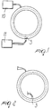
With reference to the above-cited figures, the digital data transfer device
according to the present invention is provided by means of a coil 1 which is
accommodated in a ferromagnetic core 2. The coil represents the digital data
transmitter, and sensor means 3, conveniently constituted for example by a
Hall-effect sensor, are arranged so as to face the coil and are inserted
between flux concentrators 4.
The coil 1 and the sensor 3 can alternatively be arranged so that one is on
a fixed part of a machine and the other one is on a rotating part thereof. In
particular, it is possible to arrange the coil 1 on the fixed part so that the
sensor 3 rotates rigidly with the rotating part of the machine, or vice versa.
The shape of the coil, which is circular, allows to maintain coupling
between the sensor 3 and the coil 1 throughout rotation rather than over only
a portion of a turn as occurs in conventional optical systems.
In particular, the sensor 3 can be arranged on the external tangent of the
coil 1, as shown in Figure 1, on the internal tangent of the coil 1, as shown
in Figure 2, or at the axis of the coil 1, depending on the intended
applications.
The device operates even if the transmitter part (coil 1) and the receiver
part (sensor 3) are both motionless.
Figure 1 illustrates the coil, which has a circular cross-section, with the
sensor 3 and electronic means for controlling and regulating the current 10,
which are adapted to send a current signal to the coil, and electronic
digitizing means which digitize the signal acquired by the sensor 3.
In practice, a digital signal of high logic level generates, for example, a
positive current in the coil 1, while a digital signal of low logic level
generates a negative current. The consequent positive or negative flux
generated inside the coil 1 is detected by the sensor 3, which increases or
decreases its output voltage.
For the transfer of digital data, i.e., for each digital data item (for each
data channel), it is therefore necessary to provide a coil 1 and a
corresponding sensor 3.
Figure 4 illustrates an example of circuit diagram in which a digital
signal 11 is fed into the current control and adjustment means 10, which
feed the coil 1, by means of a current I, and the coupling with the sensor 3
provides in output a voltage signal which is then digitized by the electronic
digitizing circuit 13 in order to have in output the digitized data item that
corresponds to the input data item.
Figure 5 plots the waveforms of the data of the circuit of Figure 4. In
particular, the chart designated by A corresponds to the logic signal 12 fed
into the current control and adjustment means 10.
The chart designated by B plots the current that flows in the coil as a
function of the time t (current I).
The chart designated by C instead plots the output voltage of the sensor 3
as a function of time, and the chart designated by D plots the data item in
output from the digitizing means 13.
The references A to D are also shown in Figure 4, at the positions in
which the signals subsequently plotted in Figure 5 are read.
Figure 6 illustrates an example of application of the digital data transfer
device according to the invention, in which an electronic unit 20 is arranged
on the fixed part of a machine, for example, a hosiery knitting machine or
the like, and is driven by a synchronization signal 21 which is generated for
example by counting the pulses of an encoder. The electronic unit 20
transfers, as a consequence of said synchronization signal 21, a packet of
data to an electronic unit 22 which is arranged on the moving part of the
machine.
The packet of data consists of data which represent, with an appropriate
encoding, commands toward electromechanical actuators 23 which are
arranged on the moving part of the machine.
The data are encoded and transmitted serially, in a synchronous mode,
and require only two channels with electromagnetic couplings, DATA-OUT
and CLOCK.
The electronic unit 22 on the moving part of the machine receives serial
data, decodes them, interprets them and actuates the electromechanical
actuators 23 accordingly.
The data in input in the electronic unit 22 are designated by data-in and
clock.
In turn, the electronic unit 22 replies with a packet of data which
represent the result of a series of diagnostic activities. These data, too, are
transmitted serially on a single channel with electromagnetic coupling and
in this case the sensor is on the fixed part of the machine, while the coil is
on the moving part of the machine.
In the preceding case, the transfer of the data packet of the electronic unit
20 to the unit 22 occurred serially, the coil being arranged at the fixed part
and designated by the reference numeral 1, also used in the preceding
figures, the sensor being designated by the reference numeral 3.
Figure 7 plots a typical timing chart for the transfer of data of the block
diagram of Figure 6.
In practice it has been observed that the digital data transfer device
according to the present invention fully achieves the intended aim and
objects, since it allows to perform a data transfer without physical coupling
between the transmitter and the receiver, and most of all with the possibility
of transfer throughout the rotation of the moving part with respect to the
fixed part.
The device thus conceived is susceptible of numerous modifications and
variations, all of which are within the scope of the inventive concept; all the
details may furthermore be replaced with technically equivalent elements.
In practice, the materials used, so long as they are compatible with the
specific use, as well as the dimensions, may be any according to
requirements and to the state of the art.
The disclosures in Italian Patent Application No. MI99A001930 from
which this application claims priority are incorporated herein by reference.
Where technical features mentioned in any claim are followed by
reference signs, those reference signs have been included for the sole
purpose of increasing the intelligibility of the claims and accordingly, such
reference signs do not have any limiting effect on the interpretation of each
element identified by way of example by such reference signs.