EP1085712A2 - Dispositif pour la transfert de données numériques entre une partie tournant et une partie stationaire d'une machine, en particulier pour métiers à tricoter de bas - Google Patents
Dispositif pour la transfert de données numériques entre une partie tournant et une partie stationaire d'une machine, en particulier pour métiers à tricoter de bas Download PDFInfo
- Publication number
- EP1085712A2 EP1085712A2 EP00119428A EP00119428A EP1085712A2 EP 1085712 A2 EP1085712 A2 EP 1085712A2 EP 00119428 A EP00119428 A EP 00119428A EP 00119428 A EP00119428 A EP 00119428A EP 1085712 A2 EP1085712 A2 EP 1085712A2
- Authority
- EP
- European Patent Office
- Prior art keywords
- machine
- data
- fixed part
- rotating part
- digital data
- Prior art date
- Legal status (The legal status is an assumption and is not a legal conclusion. Google has not performed a legal analysis and makes no representation as to the accuracy of the status listed.)
- Withdrawn
Links
Images


Classifications
-
- H—ELECTRICITY
- H04—ELECTRIC COMMUNICATION TECHNIQUE
- H04L—TRANSMISSION OF DIGITAL INFORMATION, e.g. TELEGRAPHIC COMMUNICATION
- H04L25/00—Baseband systems
- H04L25/02—Details ; arrangements for supplying electrical power along data transmission lines
- H04L25/0264—Arrangements for coupling to transmission lines
- H04L25/0266—Arrangements for providing Galvanic isolation, e.g. by means of magnetic or capacitive coupling
Definitions
- the present invention relates to a device for transferring digital data between a rotating part and a fixed part of a machine, particularly for hosiery knitting machines and the like.
- Optical devices are also available for transmitting digital data between two parts of a machine, but they can transmit data only when the transmitter and the receiver face each other, and therefore this entails a very small data transmission window with respect to the period, for example, of rotation of the rotating part of the machine.
- the aim of the present invention is to provide a device for transferring digital data between a rotating part and a fixed part of a machine, particularly for hosiery knitting machines and the like, which allows, without physical contact between the transmitter and the receiver, to transfer digital data with a transfer which can occur throughout the path of rotation of the rotating part of the machine.
- an object of the present invention is to provide a device for transferring digital data between a rotating part and a fixed part of a machine which allows to avoid false contacts and therefore an incorrect data transfer.
- Another object of the present invention is to provide a device for transferring digital data between a rotating part and a fixed part of a machine in which the life of the device is considerably extended with respect to conventional devices, which are limited by mechanical wear.
- Another object of the present invention is to provide a device for transferring digital data between a rotating part and a fixed part of a machine which is highly versatile and allows to easily swap the part meant to be rigidly coupled to the rotating part and the part that is rigidly coupled to the fixed part.
- Another object of the present invention is to provide a device for transferring digital data between a rotating part and a fixed part of a machine which is highly reliable, relatively easy to manufacture and at competitive costs.
- a device for transferring digital data between a rotating part and a fixed part of a machine particularly for hosiery knitting machines and the like, characterized in that it comprises data transmission means and data reception means, said data reception means being arranged so as to face said data transmission means, said data transmission means and said data reception means being arranged on two separate parts of said machine, of which one is movable and the other one is fixed.
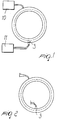
- the digital data transfer device is provided by means of a coil 1 which is accommodated in a ferromagnetic core 2.
- the coil represents the digital data transmitter, and sensor means 3, conveniently constituted for example by a Hall-effect sensor, are arranged so as to face the coil and are inserted between flux concentrators 4.
- the coil 1 and the sensor 3 can alternatively be arranged so that one is on a fixed part of a machine and the other one is on a rotating part thereof.
- the shape of the coil which is circular, allows to maintain coupling between the sensor 3 and the coil 1 throughout rotation rather than over only a portion of a turn as occurs in conventional optical systems.
- the senor 3 can be arranged on the external tangent of the coil 1, as shown in Figure 1, on the internal tangent of the coil 1, as shown in Figure 2, or at the axis of the coil 1, depending on the intended applications.
- the device operates even if the transmitter part (coil 1) and the receiver part (sensor 3) are both motionless.
- Figure 1 illustrates the coil, which has a circular cross-section, with the sensor 3 and electronic means for controlling and regulating the current 10, which are adapted to send a current signal to the coil, and electronic digitizing means which digitize the signal acquired by the sensor 3.
- a digital signal of high logic level generates, for example, a positive current in the coil 1, while a digital signal of low logic level generates a negative current.
- the consequent positive or negative flux generated inside the coil 1 is detected by the sensor 3, which increases or decreases its output voltage.
- Figure 4 illustrates an example of circuit diagram in which a digital signal 11 is fed into the current control and adjustment means 10, which feed the coil 1, by means of a current I, and the coupling with the sensor 3 provides in output a voltage signal which is then digitized by the electronic digitizing circuit 13 in order to have in output the digitized data item that corresponds to the input data item.
- FIG. 5 plots the waveforms of the data of the circuit of Figure 4.
- the chart designated by A corresponds to the logic signal 12 fed into the current control and adjustment means 10.
- the chart designated by B plots the current that flows in the coil as a function of the time t (current I).
- the chart designated by C instead plots the output voltage of the sensor 3 as a function of time, and the chart designated by D plots the data item in output from the digitizing means 13.
- Figure 6 illustrates an example of application of the digital data transfer device according to the invention, in which an electronic unit 20 is arranged on the fixed part of a machine, for example, a hosiery knitting machine or the like, and is driven by a synchronization signal 21 which is generated for example by counting the pulses of an encoder.
- the electronic unit 20 transfers, as a consequence of said synchronization signal 21, a packet of data to an electronic unit 22 which is arranged on the moving part of the machine.
- the packet of data consists of data which represent, with an appropriate encoding, commands toward electromechanical actuators 23 which are arranged on the moving part of the machine.
- the data are encoded and transmitted serially, in a synchronous mode, and require only two channels with electromagnetic couplings, DATA-OUT and CLOCK.
- the electronic unit 22 on the moving part of the machine receives serial data, decodes them, interprets them and actuates the electromechanical actuators 23 accordingly.
- the data in input in the electronic unit 22 are designated by data-in and clock.
- the electronic unit 22 replies with a packet of data which represent the result of a series of diagnostic activities.
- These data are transmitted serially on a single channel with electromagnetic coupling and in this case the sensor is on the fixed part of the machine, while the coil is on the moving part of the machine.
- Figure 7 plots a typical timing chart for the transfer of data of the block diagram of Figure 6.
- the digital data transfer device In practice it has been observed that the digital data transfer device according to the present invention fully achieves the intended aim and objects, since it allows to perform a data transfer without physical coupling between the transmitter and the receiver, and most of all with the possibility of transfer throughout the rotation of the moving part with respect to the fixed part.
- the materials used may be any according to requirements and to the state of the art.
Landscapes
- Engineering & Computer Science (AREA)
- Power Engineering (AREA)
- Computer Networks & Wireless Communication (AREA)
- Signal Processing (AREA)
- Knitting Machines (AREA)
- Near-Field Transmission Systems (AREA)
- Communication Control (AREA)
- Numerical Control (AREA)
Applications Claiming Priority (2)
| Application Number | Priority Date | Filing Date | Title |
|---|---|---|---|
| IT1999MI001930A IT1313738B1 (it) | 1999-09-16 | 1999-09-16 | Dispositivo di traferimento di dati digitali,fra una parte rotante euna parte fissa di una macchina, particolarmente per macchine per |
| ITMI991930 | 1999-09-16 |
Publications (2)
| Publication Number | Publication Date |
|---|---|
| EP1085712A2 true EP1085712A2 (fr) | 2001-03-21 |
| EP1085712A3 EP1085712A3 (fr) | 2002-03-20 |
Family
ID=11383618
Family Applications (1)
| Application Number | Title | Priority Date | Filing Date |
|---|---|---|---|
| EP00119428A Withdrawn EP1085712A3 (fr) | 1999-09-16 | 2000-09-13 | Dispositif pour la transfert de données numériques entre une partie tournant et une partie stationaire d'une machine, en particulier pour métiers à tricoter de bas |
Country Status (4)
| Country | Link |
|---|---|
| US (1) | US6345520B1 (fr) |
| EP (1) | EP1085712A3 (fr) |
| JP (1) | JP2001160844A (fr) |
| IT (1) | IT1313738B1 (fr) |
Cited By (2)
| Publication number | Priority date | Publication date | Assignee | Title |
|---|---|---|---|---|
| US6897756B2 (en) | 2002-07-26 | 2005-05-24 | Sipra Patententwicklungs- Und Beteiligungsgesellschaft Mbh | Apparatus with two components being movable relative to each other and a device for simultaneous transfer of electric power and information between these components |
| DE102006039607A1 (de) * | 2006-08-24 | 2008-04-30 | Schleifring Und Apparatebau Gmbh | Magnetischer Drehübertrager |
Families Citing this family (3)
| Publication number | Priority date | Publication date | Assignee | Title |
|---|---|---|---|---|
| CN109112712A (zh) * | 2018-09-19 | 2019-01-01 | 杭州之山智控技术有限公司 | 针织横机纱嘴控制自跑式纱嘴伺服系统及其方法 |
| JP7025026B2 (ja) * | 2019-03-20 | 2022-02-24 | Necプラットフォームズ株式会社 | 論理信号検出装置及び論理信号検出方法 |
| CN113699671B (zh) * | 2021-07-13 | 2023-04-07 | 佛山市睿宝智能科技有限公司 | 针织机选针器自编码的数据通讯方法、通讯系统和针织机 |
Family Cites Families (5)
| Publication number | Priority date | Publication date | Assignee | Title |
|---|---|---|---|---|
| GB1518498A (en) * | 1974-09-17 | 1978-07-19 | Wildt Mellor Bromley Ltd | Knitting machines |
| US4081974A (en) * | 1976-12-20 | 1978-04-04 | The Singer Company | Knitting machine carriage with hall effect detecting means |
| IT1238490B (it) * | 1989-12-01 | 1993-08-18 | Savio Spa | Dispositivo e procedimento di comando della selezione ago-ago in una macchina circolare da maglieria per teletrasmissione ad attuatori elettromagnetici rotanti |
| US5577026A (en) * | 1993-12-28 | 1996-11-19 | Analogic Corporation | Apparatus for transferring data to and from a moving device |
| DE4412958A1 (de) * | 1994-04-17 | 1995-10-19 | Schwan Ulrich | Datenübertragungseinrichtung |
-
1999
- 1999-09-16 IT IT1999MI001930A patent/IT1313738B1/it active
-
2000
- 2000-09-13 US US09/660,842 patent/US6345520B1/en not_active Expired - Fee Related
- 2000-09-13 EP EP00119428A patent/EP1085712A3/fr not_active Withdrawn
- 2000-09-18 JP JP2000281432A patent/JP2001160844A/ja active Pending
Cited By (2)
| Publication number | Priority date | Publication date | Assignee | Title |
|---|---|---|---|---|
| US6897756B2 (en) | 2002-07-26 | 2005-05-24 | Sipra Patententwicklungs- Und Beteiligungsgesellschaft Mbh | Apparatus with two components being movable relative to each other and a device for simultaneous transfer of electric power and information between these components |
| DE102006039607A1 (de) * | 2006-08-24 | 2008-04-30 | Schleifring Und Apparatebau Gmbh | Magnetischer Drehübertrager |
Also Published As
| Publication number | Publication date |
|---|---|
| IT1313738B1 (it) | 2002-09-17 |
| JP2001160844A (ja) | 2001-06-12 |
| ITMI991930A0 (it) | 1999-09-16 |
| US6345520B1 (en) | 2002-02-12 |
| EP1085712A3 (fr) | 2002-03-20 |
| ITMI991930A1 (it) | 2001-03-16 |
Similar Documents
| Publication | Publication Date | Title |
|---|---|---|
| CN104769306B (zh) | 用于确定和/或控制电动机的位置的方法 | |
| US20110045769A1 (en) | Communication device, communication system, and method for communication | |
| EP0449037B1 (fr) | Transmetteur de position | |
| US6345520B1 (en) | Device for transferring digital data between a rotating part and a fixed part of a machine, particularly for hosiery knitting machines and the like | |
| US8683101B2 (en) | Single wire bus communication protocol | |
| EP1333368A3 (fr) | Dispositif de détection d'informations trois-dimensionnelles, dispositif capteur de détection d'informations trois-dimensionnelles, et dispositif d'affichage d'informations trois-dimensionnelles | |
| US9614663B2 (en) | Method and device for serial data transmission over a bidirectional data channel | |
| CN102739352A (zh) | 用于串行通信的变换间隔编码 | |
| WO2002033358A1 (fr) | Transducteur de position | |
| Das et al. | Design of an absolute shaft encoder using optically modulated binary code | |
| EP1434382B2 (fr) | Appareil de transfert de donnees en serie | |
| US9823646B2 (en) | Device and method for generating a trigger signal in a position-measuring device and corresponding position-measuring device | |
| EP0434083A2 (fr) | Système et méthode de transmission de données | |
| EP1276260A2 (fr) | Dispositif de delai differentiel de signal, recepteur et système de communication utilisant ce dispositif | |
| CN102575945B (zh) | 变频器装置及变频器系统 | |
| IT1252301B (it) | Sistema di controllo automatico per ratiera rotativa elettronica | |
| US9923573B2 (en) | Method and device for reading a serial data stream | |
| US6321288B1 (en) | Serial IRQ slave controller with auto-synchronization | |
| US4157507A (en) | Electronic system for detecting direction of motion | |
| JPH06258099A (ja) | 多回転アブソリュートエンコーダ | |
| CN110926557B (zh) | 用于确定旋转元件的移动的器件 | |
| US20260079877A1 (en) | Readout device, system, and method | |
| JP4144522B2 (ja) | インクリメンタルリニアスケールの位置情報通信データフレーム構成方法 | |
| CN110941208B (zh) | 编码器和控制系统 | |
| AU2002222335A1 (en) | Encoding system for transmitting data and clock signals jointly across two wires |
Legal Events
| Date | Code | Title | Description |
|---|---|---|---|
| PUAI | Public reference made under article 153(3) epc to a published international application that has entered the european phase |
Free format text: ORIGINAL CODE: 0009012 |
|
| AK | Designated contracting states |
Kind code of ref document: A2 Designated state(s): AT BE CH CY DE DK ES FI FR GB GR IE IT LI LU MC NL PT SE |
|
| AX | Request for extension of the european patent |
Free format text: AL;LT;LV;MK;RO;SI |
|
| PUAL | Search report despatched |
Free format text: ORIGINAL CODE: 0009013 |
|
| AK | Designated contracting states |
Kind code of ref document: A3 Designated state(s): AT BE CH CY DE DK ES FI FR GB GR IE IT LI LU MC NL PT SE |
|
| AX | Request for extension of the european patent |
Free format text: AL;LT;LV;MK;RO;SI |
|
| STAA | Information on the status of an ep patent application or granted ep patent |
Free format text: STATUS: THE APPLICATION HAS BEEN WITHDRAWN |
|
| 18W | Application withdrawn |
Withdrawal date: 20020710 |