EP1085786A2 - Beschleunigersanlage - Google Patents
Beschleunigersanlage Download PDFInfo
- Publication number
- EP1085786A2 EP1085786A2 EP00104549A EP00104549A EP1085786A2 EP 1085786 A2 EP1085786 A2 EP 1085786A2 EP 00104549 A EP00104549 A EP 00104549A EP 00104549 A EP00104549 A EP 00104549A EP 1085786 A2 EP1085786 A2 EP 1085786A2
- Authority
- EP
- European Patent Office
- Prior art keywords
- synchrotron
- ion beam
- accelerator
- electromagnet
- producing unit
- Prior art date
- Legal status (The legal status is an assumption and is not a legal conclusion. Google has not performed a legal analysis and makes no representation as to the accuracy of the status listed.)
- Withdrawn
Links
Images


Classifications
-
- H—ELECTRICITY
- H05—ELECTRIC TECHNIQUES NOT OTHERWISE PROVIDED FOR
- H05H—PLASMA TECHNIQUE; PRODUCTION OF ACCELERATED ELECTRICALLY-CHARGED PARTICLES OR OF NEUTRONS; PRODUCTION OR ACCELERATION OF NEUTRAL MOLECULAR OR ATOMIC BEAMS
- H05H7/00—Details of devices of the types covered by groups H05H9/00, H05H11/00, H05H13/00
- H05H7/06—Two-beam arrangements; Multi-beam arrangements storage rings; Electron rings
-
- G—PHYSICS
- G21—NUCLEAR PHYSICS; NUCLEAR ENGINEERING
- G21K—HANDLING OF PARTICLES OR IONISING RADIATION NOT OTHERWISE PROVIDED FOR; IRRADIATION DEVICES; GAMMA RAY OR X-RAY MICROSCOPES
- G21K5/00—Irradiation devices
- G21K5/04—Irradiation devices with beam-forming means
Definitions
- the present invention relates to an accelerator system for accelerating an ion beam to thereby make available the beam for therapy. More particularly, the present invention is concerned with an improvement of the accelerator system such that the accelerated ion beam can be utilized for therapy with a high efficiency.
- an accelerator system designed for generating an ion beam (hereinafter also referred to simply as the beam) for utilization thereof for therapy
- an accelerator system is heretofore known which is destined for use in practicing treatment of cancer by irradiating an affected part of a cancer suffering patient.
- a typical one of such accelerator systems is disclosed in Japanese Patent Application Laid-Open Publication No. 303710/1995 (JP-A-7-303710).
- an accelerator system in which an ion source and a pre-accelerator(s) are put into operation in response to a trigger signal generated in dependence on movement (or positional change) of an affected part of a patient to thereby accelerate the beam for injecting it into a synchrotron in which the beam is further accelerated, whereon the affected part of the patient is irradiated with the accelerated beam outputted from the synchrotron.
- accelerator system for generating an accelerating beam for making use of it for therapy is disclosed in "PROC. OF THE SECOND INT' 1 SYMP. ON PET IN ONCOLOGY", May 16-18, 1993, Sendai Japan. Described in this publication is an accelerator system for producing an radioisotope by irradiating a target such as a nitrogen gas or the like for the purpose of utilizing it in diagnoses.
- the accelerator system for the treatment of cancer and the accelerator system for producing the radioisotope mentioned above are employed for the purpose of medical treatments, and thus it is considered that both the systems may be installed in one and the same facility.
- each of these accelerator systems is of a very large size and bulky. Consequently, installation of both the systems in one and the same facility at a same site requires a considerably large space. Consequently, there exists a demand for miniaturization of these accelerator systems. Besides, reduction of the manufacturing costs of these systems is also a matter of concern, needless to say.
- the beam generated by the ion source is made use of only for a short period during which the beam is injected into the synchrotron.
- the beam being generated in the ion source is not utilized.
- the accelerator system for the treatment of cancer is very poor in respect to the utilization efficiency of the ion beam.
- an accelerator system which includes an ion source for generating an ion beam, a pre-accelerator for accelerating the ion beam generated by the ion source, a radioisotope producing unit for irradiating a target with the ion beam accelerated by the pre-accelerator for thereby producing a radioisotope, a synchrotron into which the ion beam accelerated by the pre-accelerator is injected and from which the ion beam is ejected after the acceleration, and a selector electromagnet for introducing the ion beam accelerated by the pre-accelerator into either the radioisotope producing unit or the synchrotron.
- the ion beam generated in the ion source can be constantly and consecutively utilized by the radioisotope producing unit and the synchrotron owing to such arrangement that the ion beam is injected into the synchrotron when it is demanded while otherwise the ion beam is supplied to the radioisotope producing unit, whereby the beam utilization efficiency can be improved and enhanced significantly.
- the utilization efficiency of the beam can be enhanced remarkably.
- the system as a whole can be implemented in a small size at low manufacturing cost when compared with the arrangement in which the ion source and the pre-accelerator(s) are provided separately for the radioisotope producing unit and the synchrotron, respectively.
- FIG. 1 is a block diagram showing generally a configuration of an accelerator system according to a preferred embodiment of the present invention.
- the accelerator system according to the instant embodiment of the invention is comprised of an ion source 1 for generating an ion beam (hereinafter also referred to simply as the beam), a radio-frequency quadrupole linear accelerator or linac (hereinafter also referred to as the RFQ linac) 2 for accelerating the beam, a drift tube linac (also referred to as the DT linac) 3 serving also for accelerating the beam, a selector electromagnet 4 for adjusting selectively the beam orbit by deflecting the beam, power supply circuits 5a, ..., 5d for supplying electric power to the ion source 1, the RFQ linac 2, the DT linac 3 and the selector electromagnet 4, respectively, a radioisotope producing unit 6 for producing radioisotope (hereinafter also referred to as RI for short), a synchrotron 7 for
- two accelerators i.e., the RFQ linac 2 and the DT linac 3 are employed as the pre-accelerators.
- a synchrotron and an electrostatic accelerator may equally be resorted to.
- a value of voltage required for generating a beam in the ion source 1 is outputted from the controller 9 to the power supply circuit 5a. Further, voltage values or current values are outputted from the controller 9 to the power supply circuits 5b, 5c and 5d, respectively, simultaneously with the output of the voltage value from the controller 9 to the power supply circuit 5a.
- a radio-frequency voltage value required for the RFQ linac 2 to accelerate the beam generated in the ion source 1 is supplied to the power supply circuit 5b
- a radio-frequency voltage value required for the DT linac 3 to accelerate further the beam accelerated by the RFQ linac 2 is supplied to the power supply circuit 5c
- a current value required for the selector electromagnet 4 to introduce to the RI producing unit 6 the beam accelerated in the DT linac 3 is supplied to the power supply circuit 5d.
- the power supply circuit 5a is designed to supply to the ion source 1 the voltage of the value designated or commanded by the controller 9. Upon application of the voltage, the ion source 1 generates the beam conforming to the commanded voltage value, which beam is then outputted to the RFQ linac 2.
- the power supply circuit 5b supplies to the RFQ linac 2 a radio frequency voltage of the value designated by the controller 9. In response to application of this voltage, the RFQ linac 2 accelerates the beam outputted from the ion source 1 in conformance with the radio-frequency voltage, the accelerated beam being then inputted to the DT linac 3.
- the power supply circuit 5c supplies to the DT linac 3 the radio-frequency voltage of the value commanded by the controller 9.
- the DT linac 3 accelerates the beam outputted from the RFQ linac 2 in conformance to the commanded voltage, the beam accelerated being then outputted to the selector electromagnet 4.
- the power supply circuit 5d outputs a current of the value designated by the controller 9 to the selector electromagnet 4 which responds thereto by generating the magnetic field conforming to the current command to thereby deflect correspondingly the beam outputted from the DT linac 3, whereby the beam orbit is so adjusted that the beam can be introduced into the RI producing unit 6, which in turn irradiates a target (e.g. nitrogen gas) with the beam introduced via the selector electromagnet 4 to thereby produce RI, e.g. radioisotope of nitrogen.
- a target e.g. nitrogen gas
- Figure 2A shows a current value of the beam generated by the ion source 1.
- the beam in the ion source 1, the beam is generated in the form of pulse-like beam shots, so to say, periodically at a predetermined interval.
- This sort of beam can be generated by designating the voltage value in a pulse-like fashion periodically at the predetermined interval to the power supply circuit 5a from the controller 9.
- Shown in Fig. 2B is a waveform of the current supplied to the selector electromagnet 4 from the power supply circuit 5d.
- the current of the value or level Ia is supplied to the selector electromagnet 4.
- Fig. 2C is a current value or intensity of the beam introduced into the RI producing unit 6. It can be seen that when the current Ia shown in Fig. 2B is supplied to the selector electromagnet 4, the pulse-like beam (or a series of beam shots, so to say) is introduced into the RI producing unit 6.
- Inputted to the controller 9 are an injection command and an ejection command from the irradiation system 8.
- the controller 9 changes the current value command issued to the power supply circuit 5d to the value or level Ib from the level Ia.
- the current level Ib represents the value of current required by the selector electromagnet 4 for introducing the beam into the synchrotron 7.
- the power supply circuit 5d responds to the current value issued from the controller 9 to thereby change the output current value to the level Ib from Ia, as is illustrated in Fig. 2B.
- the magnetic field generated by the selector electromagnet 4 changes as well, involving corresponding change of the orbit of the beam deflected under the influence of the magnetic field generated by the selector electromagnet 4. Consequently, the beam is injected into the synchrotron 7.
- the current value issued to the power supply circuit 5d from the controller 9 is again changed over to the level Ia from Ib.
- the power supply circuit 5d changes the output current value thereof from the level Ia to Ib, as illustrated in Fig. 2B.
- the beam is again introduced into the RI producing unit 6 via the selector electromagnet 4.
- the selector electromagnet 4 employed in the accelerator system according to the instant embodiment of the invention should preferably be implemented in the form of a laminated electromagnet constituted by laminating a plurality of steel sheets each of about 1 mm in thickness for realizing the selector operation mentioned above at a high speed.
- the beam deflected toward the synchrotron 7 by the selector electromagnet 4 is then injected into the synchrotron 7 by means of a beam injection unit 71.
- the current or intensity of the beam injected into the synchrotron 7 is illustrated in Fig. 2E.
- the beam can be injected into the synchrotron 7 only when the current of the level Ib is supplied to the selector electromagnet 4.
- the beam injected into the synchrotron 7 is deflected under the influence of the magnetic field generated by a deflection electromagnet 72. In this way, the orbit of the beam is controlled by the deflection electromagnet 72.
- the beam undergoes a tuning control under the magnetic fields generated by a quadrupole electromagnet 73 so that the beam can circulate or run around through a vacuum duct 74 stably.
- the deflection electromagnet 72 and the quadrupole electromagnet 73 are provided with a power supply circuit (not shown), respectively, wherein the strength of the magnetic field generated by the electromagnet mentioned above is controlled by the current supplied from the associated power supply circuit.
- the currents supplied to the deflection electromagnet 72 and the quadrupole electromagnet 73 are controlled by the controller 9.
- a radio-frequency voltage is applied to the beam circulating through the vacuum duct 74, as a result of which energy of the beam increases. In other words, the beam is accelerated.
- the strength of the magnetic fields generated by the deflection electromagnet 72 and the quadrupole electromagnet 73 is also increased, whereby the beam can circulate or run around through the vacuum duct 74 with high stability.
- Fig. 2F there is illustrated a waveform of the current supplied to the deflection electromagnet 72. As can be seen from this figure, the current supplied to the deflection electromagnet 72 is increased upon acceleration of the beam. Accordingly, the strength of the magnetic field generated by the deflection electromagnet 72 is also intensified.
- the beam accelerating operation is terminated.
- an ejection command is issued to the controller 9 from the irradiation system 8, as illustrated in Fig. 2D.
- the controller 9 causes a hexapole electromagnet 76 to apply a hexapole magnetic field to the beam, bringing about resonance in the beam, which results in increasing of the vibration amplitude of the beam.
- the beam is ejected from the synchrotron 7 through a beam ejection unit 77. After the ejection of the beam from the synchrotron 7, the strength of the magnetic field generated by the deflection electromagnet 72 is lowered.
- the current supplied to the deflection electromagnet 72 is maintained to be constant during a time period from the acceleration of the beam to the ejection thereof and decreased after the beam ejection, as is illustrated in Fig. 2F.
- the beam ejected from the synchrotron 7 is transported to the irradiation system 8 for irradiation of an affected part of a patient with the beam. It goes without saying that during the period in which the beam is accelerated for ejection by the synchrotron 7, the ion source 1 continues to generate the beam to be supplied to the RI producing unit 6.
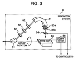
- Figure 3 is a view showing schematically a structure of the irradiation system 8.
- the beam ejected from the synchrotron 7 undergoes adjustment in respect to the orbit and the tuning by means of a deflection electromagnet 81 and a quadrupole electromagnet 82 of the irradiation system 8 to be subsequently transported to scanning electromagnets 83a and 83b which are provided for beam deflection and scanning.
- the scanning electromagnets 83a and 83b are designed to generate magnetic fields orthogonal to each other.
- the beam passed through the scanning electromagnets 83a and 83b is used for irradiating an affected part of a patient positioned fixedly on a treatment bed after having passed through a dose monitor 84 which is so designed as to measure the dose of the beam to thereby issue an ejection stop command to the controller 9 when the dose measured has attained a preset value of the dose.
- the controller 9 stops the ejection of the beam.
- a flow rate monitor 85 is operatively connected to the patient for measuring the flow rate of his or her breathing or respiration.
- the output signal of the flow rate monitor 85 indicative of the respiration rate is inputted to a compactor 86 for which a first preset value and a second preset value are set in advance.
- the compactor 86 compares the inputted respiration rate with the first preset value and the second preset value, respectively.
- the compactor 86 issues an injection command to the controller 9 while issuing an ejection command when the respiration rate has attained the second preset value.
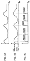
- Figs. 4A, 4B and 4C show positional change of the affected part as a function of time lapse, Fig. 4B shows change of the respiration rate of a patient as measured by the flow rate monitor 85, and Fig. 4C shows timings at which the injection command and the ejection command are outputted, respectively.
- the position of the affected part will change in conformance to the breathing or respiration of the patient, which means that difficulty is encountered in irradiating the affected part with the beam with a desired accuracy.
- the position of the affected part changes substantially synchronously with the changes of the respiration flow rate of the patient and that the change of the position of the affected part becomes minimum at a local minimum value of the respiration flow rate, as can be seen in Figs. 4A and 4B.
- the local minimum value of the respiration flow rate is set as the second preset value mentioned previously, as is shown in Fig. 4B, wherein the ejection command is outputted to the controller 9 when the respiration flow rate assumes the local minimum value, as shown in Fig. 4C.
- the local maximum value of the respiration flow rate is set as the first preset value mentioned hereinbefore, and the injection command is issued to the controller 9 when the respiration flow rate assumes the local maximum value to thereby allow the beam to be injected to the synchrotron 7.
- the amount of excitation of the selector electromagnet 4 is changed so as to allow the beam to be injected to the synchrotron 7 in response to the injection command issued to the controller 9 when the respiration flow rate of the affected part assumes the local maximum value while the synchrotron 7 can assume the state capable of ejecting the beam at the time point when the local minimum value makes appearance in the flow rate of respiration.
- the affected part of the patient can accurately be irradiated with the beam, to a great advantage.
- the respiration monitor for measuring the respiration flow rate is employed for detecting the positional change of the affected part in the accelerator system according to the instant embodiment, the invention is never restricted to the use of such respiration monitor.
- any appropriate device capable of directly measuring the positional change of the affected part such as e.g. a distortion sensor, an image analyzer for analyzing an image of the affected part taken by a camera or the like can equally be made use of.
- the system according to the present invention is effective even for the case where the affected part is located at a position remote from the lung and insusceptible to positional change or displacement.
- the control of the synchrotron 7 in dependence on the flow rate of respiration can simply be spared, and it is sufficient to carry out the beam ejection, acceleration and ejection periodically in a predetermined sequence.
- the ion source 1, the RFQ linac 2, the DT linac 3, the selector electromagnet 4 and the power supply circuits 5a, ..., 5d are disposed within a pre-accelerator chamber 101, while the RI producing unit 6 is housed within an RI producing chamber 102. Further, the synchrotron 7 is accommodated within a synchrotron chamber 103 with the irradiation system 8 being disposed within an irradiation chamber 104.
- the pre-accelerator chamber 101, the RI producing chamber 102, the synchrotron chamber 103 and the irradiation chamber 104 are mutually radiation-shielded by shielding walls.
- shielding shutters are installed in the beam passage (vacuum duct) at positions between the selector electromagnet 4 and the RI producing unit 6 and between the selector electromagnet 4 and the synchrotron 7, respectively. By closing the shielding shutters, the beam (radiation lays) can be shielded.
- the beam can be so deflected as to be introduced into the RI producing unit 6 by means of the selector electromagnet 4 while the shielding shutter disposed between the selector electromagnet 4 and the synchrotron 7 is closed for shielding the synchrotron chamber 103 completely from the radiation lays so that the person can carry out his or her works with safety.
- the beam is directed into the synchrotron 7 by means of the selector electromagnet 4 while the shielding shutter disposed between the selector electromagnet 4 and the RI producing unit 6 is closed to thereby shield the RI producing chamber 102 completely from the radiation lays.
- excitation of the selector electromagnet 4 may be interrupted to allow the beam to be discarded in a beam dump 10 or alternatively beam generation by the ion source 1 may be stopped.
- the selector electromagnet 4 is provided at a stage succeeding to the DT linac 3 so that the beam can be injected into the synchrotron 7 by means of the selector electromagnet 4 when the beam is demanded by the synchrotron 7 while the beam is fed to the RI producing unit 6 by the selector electromagnet 4 when no beam is required in the synchrotron 7.
- the beam generated by the ion source 1 can be utilized constantly and continuously by the RI producing unit 6 or the synchrotron 7, whereby the utilization ratio or efficiency of beam can significantly be enhanced, to a great advantage.
- the utilization efficiency of the beam can be enhanced remarkably.
- the RI producing unit demands the beam of a large current at low energy while the high-energy beam of a small current is required for the medical treatment of cancer, it is safe to say that the combination of the RI producing unit and the synchrotron for the medical treatment of cancer or the like is an optimal one.
- the apparatus as a whole can be implemented in a small size at low manufacturing cost when compared with the arrangement in which the ion source 1, the RFQ linac 2 and the DT linac 3 are provided separately for the RI producing unit 6 and the synchrotron 7, respectively.
- the DT linac is disposed between the selector electromagnet 4 and the RI producing unit 6 so that the beam can further be accelerated, the species or types of the producible radioisotopes can be increased while the time taken for production of radioisotopes can be reduced.
- the ion beam generated in the ion source can constantly be utilized by the RI producing unit or the synchrotron by virtue of such arrangement that the ion beam is injected into the synchrotron when it is demanded while otherwise the ion beam is supplied to the RI producing unit, whereby the beam utilization efficiency can be improved and enhanced significantly.
- the accelerator system according to the present invention can be miniaturized and implemented inexpensively when compared with the system in which the ion sources and the pre-accelerators are provided separately for the RI producing unit and the synchrotron, respectively.
Landscapes
- Physics & Mathematics (AREA)
- Engineering & Computer Science (AREA)
- General Engineering & Computer Science (AREA)
- High Energy & Nuclear Physics (AREA)
- Plasma & Fusion (AREA)
- Spectroscopy & Molecular Physics (AREA)
- Radiation-Therapy Devices (AREA)
- Particle Accelerators (AREA)
Applications Claiming Priority (2)
| Application Number | Priority Date | Filing Date | Title |
|---|---|---|---|
| JP25988999A JP2001085200A (ja) | 1999-09-14 | 1999-09-14 | 加速器システム |
| JP25988999 | 1999-09-14 |
Publications (2)
| Publication Number | Publication Date |
|---|---|
| EP1085786A2 true EP1085786A2 (de) | 2001-03-21 |
| EP1085786A3 EP1085786A3 (de) | 2004-02-04 |
Family
ID=17340355
Family Applications (1)
| Application Number | Title | Priority Date | Filing Date |
|---|---|---|---|
| EP00104549A Withdrawn EP1085786A3 (de) | 1999-09-14 | 2000-03-13 | Beschleunigersanlage |
Country Status (5)
| Country | Link |
|---|---|
| US (1) | US6580084B1 (de) |
| EP (1) | EP1085786A3 (de) |
| JP (1) | JP2001085200A (de) |
| AU (1) | AU737671B2 (de) |
| SG (1) | SG97865A1 (de) |
Cited By (5)
| Publication number | Priority date | Publication date | Assignee | Title |
|---|---|---|---|---|
| US6677597B1 (en) * | 1999-04-12 | 2004-01-13 | Gesellschaft Fuer Schwerionenforschung Mbh | Device and method for controlling a raster scanner in ion-beam therapy |
| AU769874B2 (en) * | 2001-09-11 | 2004-02-05 | Hitachi Limited | Accelerator system and medical accelerator facility |
| US7317192B2 (en) | 2003-06-02 | 2008-01-08 | Fox Chase Cancer Center | High energy polyenergetic ion selection systems, ion beam therapy systems, and ion beam treatment centers |
| EP1530410A3 (de) * | 2003-11-07 | 2009-11-04 | Hitachi Ltd. | Teilchen-Therapieanlage |
| CN101815399B (zh) * | 2009-01-12 | 2011-09-21 | 中国科学院近代物理研究所 | 重离子治癌同步加速器中射频激励引出方法及其装置 |
Families Citing this family (114)
| Publication number | Priority date | Publication date | Assignee | Title |
|---|---|---|---|---|
| UA42392C2 (uk) * | 2001-02-13 | 2004-04-15 | Александра Клавдія Мельник | Багатоканальний лінійний індукційний прискорювач заряджених частинок |
| JP3859605B2 (ja) | 2003-03-07 | 2006-12-20 | 株式会社日立製作所 | 粒子線治療システム及び粒子線出射方法 |
| US7140771B2 (en) * | 2003-09-22 | 2006-11-28 | Leek Paul H | X-ray producing device with reduced shielding |
| US7045978B2 (en) * | 2004-03-10 | 2006-05-16 | Viara Research, Llc | Multi-channel induction accelerator |
| US7030577B2 (en) * | 2004-03-10 | 2006-04-18 | Viara Research, Llc | Multi-channel undulative induction accelerator |
| DE102004027071A1 (de) * | 2004-05-19 | 2006-01-05 | Gesellschaft für Schwerionenforschung mbH | Strahlzuteilungsvorrichtung und Strahlzuteilungsverfahren für medizinische Teilchenbeschleuniger |
| US7012385B1 (en) * | 2004-09-24 | 2006-03-14 | Viara Research, Llc | Multi-channel induction accelerator with external channels |
| JP2006098056A (ja) * | 2004-09-28 | 2006-04-13 | Hitachi Ltd | 粒子線照射システム |
| US8363775B1 (en) * | 2006-11-27 | 2013-01-29 | The United States Of America As Represented By The Secretary Of The Navy | Doping of semiconductor materials by nuclear transmutation |
| DK2106678T3 (da) * | 2006-12-28 | 2010-09-20 | Fond Per Adroterapia Oncologic | Ionaccelerationssystem til medicinske og/eller andre anvendelser |
| DE102007020599A1 (de) * | 2007-05-02 | 2008-11-06 | Siemens Ag | Partikeltherapieanlage |
| US9910166B2 (en) | 2008-05-22 | 2018-03-06 | Stephen L. Spotts | Redundant charged particle state determination apparatus and method of use thereof |
| US9682254B2 (en) | 2008-05-22 | 2017-06-20 | Vladimir Balakin | Cancer surface searing apparatus and method of use thereof |
| US9095040B2 (en) | 2008-05-22 | 2015-07-28 | Vladimir Balakin | Charged particle beam acceleration and extraction method and apparatus used in conjunction with a charged particle cancer therapy system |
| US8399866B2 (en) | 2008-05-22 | 2013-03-19 | Vladimir Balakin | Charged particle extraction apparatus and method of use thereof |
| US9177751B2 (en) | 2008-05-22 | 2015-11-03 | Vladimir Balakin | Carbon ion beam injector apparatus and method of use thereof |
| WO2009142548A2 (en) | 2008-05-22 | 2009-11-26 | Vladimir Yegorovich Balakin | X-ray method and apparatus used in conjunction with a charged particle cancer therapy system |
| US9616252B2 (en) | 2008-05-22 | 2017-04-11 | Vladimir Balakin | Multi-field cancer therapy apparatus and method of use thereof |
| US8766217B2 (en) | 2008-05-22 | 2014-07-01 | Vladimir Yegorovich Balakin | Multi-field charged particle cancer therapy method and apparatus |
| US8129699B2 (en) | 2008-05-22 | 2012-03-06 | Vladimir Balakin | Multi-field charged particle cancer therapy method and apparatus coordinated with patient respiration |
| US9737734B2 (en) | 2008-05-22 | 2017-08-22 | Susan L. Michaud | Charged particle translation slide control apparatus and method of use thereof |
| US8598543B2 (en) | 2008-05-22 | 2013-12-03 | Vladimir Balakin | Multi-axis/multi-field charged particle cancer therapy method and apparatus |
| EP2283713B1 (de) | 2008-05-22 | 2018-03-28 | Vladimir Yegorovich Balakin | Vorrichtung zur krebstherapie mit geladenen teilchen mit mehreren achsen |
| US8373143B2 (en) | 2008-05-22 | 2013-02-12 | Vladimir Balakin | Patient immobilization and repositioning method and apparatus used in conjunction with charged particle cancer therapy |
| US9579525B2 (en) | 2008-05-22 | 2017-02-28 | Vladimir Balakin | Multi-axis charged particle cancer therapy method and apparatus |
| US8374314B2 (en) | 2008-05-22 | 2013-02-12 | Vladimir Balakin | Synchronized X-ray / breathing method and apparatus used in conjunction with a charged particle cancer therapy system |
| US8045679B2 (en) * | 2008-05-22 | 2011-10-25 | Vladimir Balakin | Charged particle cancer therapy X-ray method and apparatus |
| US8144832B2 (en) | 2008-05-22 | 2012-03-27 | Vladimir Balakin | X-ray tomography method and apparatus used in conjunction with a charged particle cancer therapy system |
| US9782140B2 (en) | 2008-05-22 | 2017-10-10 | Susan L. Michaud | Hybrid charged particle / X-ray-imaging / treatment apparatus and method of use thereof |
| US7943913B2 (en) | 2008-05-22 | 2011-05-17 | Vladimir Balakin | Negative ion source method and apparatus used in conjunction with a charged particle cancer therapy system |
| US8089054B2 (en) | 2008-05-22 | 2012-01-03 | Vladimir Balakin | Charged particle beam acceleration and extraction method and apparatus used in conjunction with a charged particle cancer therapy system |
| US8710462B2 (en) | 2008-05-22 | 2014-04-29 | Vladimir Balakin | Charged particle cancer therapy beam path control method and apparatus |
| WO2009142547A2 (en) | 2008-05-22 | 2009-11-26 | Vladimir Yegorovich Balakin | Charged particle beam acceleration method and apparatus as part of a charged particle cancer therapy system |
| US8969834B2 (en) | 2008-05-22 | 2015-03-03 | Vladimir Balakin | Charged particle therapy patient constraint apparatus and method of use thereof |
| US8368038B2 (en) | 2008-05-22 | 2013-02-05 | Vladimir Balakin | Method and apparatus for intensity control of a charged particle beam extracted from a synchrotron |
| US9737272B2 (en) | 2008-05-22 | 2017-08-22 | W. Davis Lee | Charged particle cancer therapy beam state determination apparatus and method of use thereof |
| US8519365B2 (en) | 2008-05-22 | 2013-08-27 | Vladimir Balakin | Charged particle cancer therapy imaging method and apparatus |
| US8637833B2 (en) | 2008-05-22 | 2014-01-28 | Vladimir Balakin | Synchrotron power supply apparatus and method of use thereof |
| US10143854B2 (en) | 2008-05-22 | 2018-12-04 | Susan L. Michaud | Dual rotation charged particle imaging / treatment apparatus and method of use thereof |
| CA2725493C (en) | 2008-05-22 | 2015-08-18 | Vladimir Yegorovich Balakin | Charged particle cancer therapy beam path control method and apparatus |
| US9737733B2 (en) | 2008-05-22 | 2017-08-22 | W. Davis Lee | Charged particle state determination apparatus and method of use thereof |
| US8642978B2 (en) | 2008-05-22 | 2014-02-04 | Vladimir Balakin | Charged particle cancer therapy dose distribution method and apparatus |
| US9044600B2 (en) | 2008-05-22 | 2015-06-02 | Vladimir Balakin | Proton tomography apparatus and method of operation therefor |
| US9056199B2 (en) | 2008-05-22 | 2015-06-16 | Vladimir Balakin | Charged particle treatment, rapid patient positioning apparatus and method of use thereof |
| WO2009142545A2 (en) | 2008-05-22 | 2009-11-26 | Vladimir Yegorovich Balakin | Charged particle cancer therapy patient positioning method and apparatus |
| US9744380B2 (en) | 2008-05-22 | 2017-08-29 | Susan L. Michaud | Patient specific beam control assembly of a cancer therapy apparatus and method of use thereof |
| US9937362B2 (en) | 2008-05-22 | 2018-04-10 | W. Davis Lee | Dynamic energy control of a charged particle imaging/treatment apparatus and method of use thereof |
| US10684380B2 (en) | 2008-05-22 | 2020-06-16 | W. Davis Lee | Multiple scintillation detector array imaging apparatus and method of use thereof |
| US8093564B2 (en) * | 2008-05-22 | 2012-01-10 | Vladimir Balakin | Ion beam focusing lens method and apparatus used in conjunction with a charged particle cancer therapy system |
| US8309941B2 (en) * | 2008-05-22 | 2012-11-13 | Vladimir Balakin | Charged particle cancer therapy and patient breath monitoring method and apparatus |
| US8569717B2 (en) | 2008-05-22 | 2013-10-29 | Vladimir Balakin | Intensity modulated three-dimensional radiation scanning method and apparatus |
| US8841866B2 (en) | 2008-05-22 | 2014-09-23 | Vladimir Yegorovich Balakin | Charged particle beam extraction method and apparatus used in conjunction with a charged particle cancer therapy system |
| US8975600B2 (en) | 2008-05-22 | 2015-03-10 | Vladimir Balakin | Treatment delivery control system and method of operation thereof |
| US9155911B1 (en) | 2008-05-22 | 2015-10-13 | Vladimir Balakin | Ion source method and apparatus used in conjunction with a charged particle cancer therapy system |
| US8288742B2 (en) | 2008-05-22 | 2012-10-16 | Vladimir Balakin | Charged particle cancer therapy patient positioning method and apparatus |
| US10029122B2 (en) | 2008-05-22 | 2018-07-24 | Susan L. Michaud | Charged particle—patient motion control system apparatus and method of use thereof |
| US7939809B2 (en) * | 2008-05-22 | 2011-05-10 | Vladimir Balakin | Charged particle beam extraction method and apparatus used in conjunction with a charged particle cancer therapy system |
| US10548551B2 (en) | 2008-05-22 | 2020-02-04 | W. Davis Lee | Depth resolved scintillation detector array imaging apparatus and method of use thereof |
| US8188688B2 (en) | 2008-05-22 | 2012-05-29 | Vladimir Balakin | Magnetic field control method and apparatus used in conjunction with a charged particle cancer therapy system |
| US8198607B2 (en) * | 2008-05-22 | 2012-06-12 | Vladimir Balakin | Tandem accelerator method and apparatus used in conjunction with a charged particle cancer therapy system |
| US7940894B2 (en) * | 2008-05-22 | 2011-05-10 | Vladimir Balakin | Elongated lifetime X-ray method and apparatus used in conjunction with a charged particle cancer therapy system |
| US10070831B2 (en) | 2008-05-22 | 2018-09-11 | James P. Bennett | Integrated cancer therapy—imaging apparatus and method of use thereof |
| US8907309B2 (en) | 2009-04-17 | 2014-12-09 | Stephen L. Spotts | Treatment delivery control system and method of operation thereof |
| US8718231B2 (en) | 2008-05-22 | 2014-05-06 | Vladimir Balakin | X-ray tomography method and apparatus used in conjunction with a charged particle cancer therapy system |
| US9855444B2 (en) | 2008-05-22 | 2018-01-02 | Scott Penfold | X-ray detector for proton transit detection apparatus and method of use thereof |
| US8624528B2 (en) | 2008-05-22 | 2014-01-07 | Vladimir Balakin | Method and apparatus coordinating synchrotron acceleration periods with patient respiration periods |
| US8373146B2 (en) | 2008-05-22 | 2013-02-12 | Vladimir Balakin | RF accelerator method and apparatus used in conjunction with a charged particle cancer therapy system |
| US8178859B2 (en) | 2008-05-22 | 2012-05-15 | Vladimir Balakin | Proton beam positioning verification method and apparatus used in conjunction with a charged particle cancer therapy system |
| US9974978B2 (en) | 2008-05-22 | 2018-05-22 | W. Davis Lee | Scintillation array apparatus and method of use thereof |
| US9981147B2 (en) | 2008-05-22 | 2018-05-29 | W. Davis Lee | Ion beam extraction apparatus and method of use thereof |
| US9498649B2 (en) | 2008-05-22 | 2016-11-22 | Vladimir Balakin | Charged particle cancer therapy patient constraint apparatus and method of use thereof |
| US10092776B2 (en) | 2008-05-22 | 2018-10-09 | Susan L. Michaud | Integrated translation/rotation charged particle imaging/treatment apparatus and method of use thereof |
| US8378311B2 (en) | 2008-05-22 | 2013-02-19 | Vladimir Balakin | Synchrotron power cycling apparatus and method of use thereof |
| US7953205B2 (en) * | 2008-05-22 | 2011-05-31 | Vladimir Balakin | Synchronized X-ray / breathing method and apparatus used in conjunction with a charged particle cancer therapy system |
| US8896239B2 (en) | 2008-05-22 | 2014-11-25 | Vladimir Yegorovich Balakin | Charged particle beam injection method and apparatus used in conjunction with a charged particle cancer therapy system |
| US8129694B2 (en) | 2008-05-22 | 2012-03-06 | Vladimir Balakin | Negative ion beam source vacuum method and apparatus used in conjunction with a charged particle cancer therapy system |
| US8378321B2 (en) | 2008-05-22 | 2013-02-19 | Vladimir Balakin | Charged particle cancer therapy and patient positioning method and apparatus |
| US8436327B2 (en) | 2008-05-22 | 2013-05-07 | Vladimir Balakin | Multi-field charged particle cancer therapy method and apparatus |
| US8373145B2 (en) | 2008-05-22 | 2013-02-12 | Vladimir Balakin | Charged particle cancer therapy system magnet control method and apparatus |
| US9168392B1 (en) | 2008-05-22 | 2015-10-27 | Vladimir Balakin | Charged particle cancer therapy system X-ray apparatus and method of use thereof |
| US8625739B2 (en) | 2008-07-14 | 2014-01-07 | Vladimir Balakin | Charged particle cancer therapy x-ray method and apparatus |
| US8229072B2 (en) | 2008-07-14 | 2012-07-24 | Vladimir Balakin | Elongated lifetime X-ray method and apparatus used in conjunction with a charged particle cancer therapy system |
| US8627822B2 (en) | 2008-07-14 | 2014-01-14 | Vladimir Balakin | Semi-vertical positioning method and apparatus used in conjunction with a charged particle cancer therapy system |
| BRPI0924903B8 (pt) | 2009-03-04 | 2021-06-22 | Zakrytoe Aktsionernoe Obshchestvo Protom | aparelho para geração de um feixe de íons negativos para uso em uma terapia por radiação de partículas carregadas e método para geração de um feixe de íons negativos para uso com terapia por radiação de partículas carregadas |
| US10086214B2 (en) | 2010-04-16 | 2018-10-02 | Vladimir Balakin | Integrated tomography—cancer treatment apparatus and method of use thereof |
| US10376717B2 (en) | 2010-04-16 | 2019-08-13 | James P. Bennett | Intervening object compensating automated radiation treatment plan development apparatus and method of use thereof |
| US11648420B2 (en) | 2010-04-16 | 2023-05-16 | Vladimir Balakin | Imaging assisted integrated tomography—cancer treatment apparatus and method of use thereof |
| US10638988B2 (en) | 2010-04-16 | 2020-05-05 | Scott Penfold | Simultaneous/single patient position X-ray and proton imaging apparatus and method of use thereof |
| US10625097B2 (en) | 2010-04-16 | 2020-04-21 | Jillian Reno | Semi-automated cancer therapy treatment apparatus and method of use thereof |
| US10751551B2 (en) | 2010-04-16 | 2020-08-25 | James P. Bennett | Integrated imaging-cancer treatment apparatus and method of use thereof |
| US10349906B2 (en) | 2010-04-16 | 2019-07-16 | James P. Bennett | Multiplexed proton tomography imaging apparatus and method of use thereof |
| US10589128B2 (en) | 2010-04-16 | 2020-03-17 | Susan L. Michaud | Treatment beam path verification in a cancer therapy apparatus and method of use thereof |
| US10179250B2 (en) | 2010-04-16 | 2019-01-15 | Nick Ruebel | Auto-updated and implemented radiation treatment plan apparatus and method of use thereof |
| US10188877B2 (en) | 2010-04-16 | 2019-01-29 | W. Davis Lee | Fiducial marker/cancer imaging and treatment apparatus and method of use thereof |
| US10556126B2 (en) | 2010-04-16 | 2020-02-11 | Mark R. Amato | Automated radiation treatment plan development apparatus and method of use thereof |
| US10555710B2 (en) | 2010-04-16 | 2020-02-11 | James P. Bennett | Simultaneous multi-axes imaging apparatus and method of use thereof |
| US9737731B2 (en) | 2010-04-16 | 2017-08-22 | Vladimir Balakin | Synchrotron energy control apparatus and method of use thereof |
| US10518109B2 (en) | 2010-04-16 | 2019-12-31 | Jillian Reno | Transformable charged particle beam path cancer therapy apparatus and method of use thereof |
| US8963112B1 (en) | 2011-05-25 | 2015-02-24 | Vladimir Balakin | Charged particle cancer therapy patient positioning method and apparatus |
| US8933651B2 (en) | 2012-11-16 | 2015-01-13 | Vladimir Balakin | Charged particle accelerator magnet apparatus and method of use thereof |
| JP5963308B2 (ja) * | 2012-12-03 | 2016-08-03 | 株式会社日立製作所 | 粒子線照射システム及び運転制御パターンデータの生成方法 |
| CN104505135A (zh) * | 2014-12-18 | 2015-04-08 | 清华大学 | 一种电子直线加速器的屏蔽装置以及屏蔽方法 |
| US9907981B2 (en) | 2016-03-07 | 2018-03-06 | Susan L. Michaud | Charged particle translation slide control apparatus and method of use thereof |
| US10118052B2 (en) * | 2016-05-27 | 2018-11-06 | Stephen L. Spotts | Charged particle cancer therapy installation system |
| US10037863B2 (en) | 2016-05-27 | 2018-07-31 | Mark R. Amato | Continuous ion beam kinetic energy dissipater apparatus and method of use thereof |
| US10843011B2 (en) | 2017-07-21 | 2020-11-24 | Varian Medical Systems, Inc. | Particle beam gun control systems and methods |
| US10609806B2 (en) | 2017-07-21 | 2020-03-31 | Varian Medical Systems Particle Therapy Gmbh | Energy modulation of a cyclotron beam |
| US10183179B1 (en) | 2017-07-21 | 2019-01-22 | Varian Medical Systems, Inc. | Triggered treatment systems and methods |
| US10245448B2 (en) | 2017-07-21 | 2019-04-02 | Varian Medical Systems Particle Therapy Gmbh | Particle beam monitoring systems and methods |
| US10092774B1 (en) | 2017-07-21 | 2018-10-09 | Varian Medical Systems International, AG | Dose aspects of radiation therapy planning and treatment |
| US10549117B2 (en) | 2017-07-21 | 2020-02-04 | Varian Medical Systems, Inc | Geometric aspects of radiation therapy planning and treatment |
| US11712579B2 (en) | 2017-07-21 | 2023-08-01 | Varian Medical Systems, Inc. | Range compensators for radiation therapy |
| US11590364B2 (en) | 2017-07-21 | 2023-02-28 | Varian Medical Systems International Ag | Material inserts for radiation therapy |
| CN116723626B (zh) * | 2023-05-30 | 2025-12-12 | 中国科学院上海高等研究院 | 离子注入器 |
Citations (1)
| Publication number | Priority date | Publication date | Assignee | Title |
|---|---|---|---|---|
| JPH07303710A (ja) | 1994-03-17 | 1995-11-21 | Hitachi Ltd | 放射線照射方法及び放射線照射装置 |
Family Cites Families (8)
| Publication number | Priority date | Publication date | Assignee | Title |
|---|---|---|---|---|
| US3343020A (en) * | 1964-10-08 | 1967-09-19 | Hayden S Gordon | Apparatus for the acceleration, storage and utilization of counter-rotating charged particle beams |
| US4870287A (en) | 1988-03-03 | 1989-09-26 | Loma Linda University Medical Center | Multi-station proton beam therapy system |
| JPH03227000A (ja) | 1990-01-31 | 1991-10-07 | Ishikawajima Harima Heavy Ind Co Ltd | Sor装置 |
| JPH05288900A (ja) | 1992-04-14 | 1993-11-05 | Mitsubishi Electric Corp | ビーム方向振り分け用偏向電磁石装置 |
| JP3227000B2 (ja) | 1993-01-21 | 2001-11-12 | 株式会社日立製作所 | モータの速度制御装置 |
| US5538494A (en) * | 1994-03-17 | 1996-07-23 | Hitachi, Ltd. | Radioactive beam irradiation method and apparatus taking movement of the irradiation area into consideration |
| JPH10106800A (ja) * | 1996-09-25 | 1998-04-24 | Hitachi Ltd | 荷電粒子ビーム照射装置 |
| JPH11345700A (ja) * | 1998-06-02 | 1999-12-14 | Hitachi Ltd | 電磁石及びそれを用いたシンクロトロン |
-
1999
- 1999-09-14 JP JP25988999A patent/JP2001085200A/ja active Pending
-
2000
- 2000-03-13 US US09/524,554 patent/US6580084B1/en not_active Expired - Fee Related
- 2000-03-13 EP EP00104549A patent/EP1085786A3/de not_active Withdrawn
- 2000-03-13 AU AU20840/00A patent/AU737671B2/en not_active Ceased
- 2000-03-13 SG SG200001449A patent/SG97865A1/en unknown
Patent Citations (1)
| Publication number | Priority date | Publication date | Assignee | Title |
|---|---|---|---|---|
| JPH07303710A (ja) | 1994-03-17 | 1995-11-21 | Hitachi Ltd | 放射線照射方法及び放射線照射装置 |
Cited By (6)
| Publication number | Priority date | Publication date | Assignee | Title |
|---|---|---|---|---|
| US6677597B1 (en) * | 1999-04-12 | 2004-01-13 | Gesellschaft Fuer Schwerionenforschung Mbh | Device and method for controlling a raster scanner in ion-beam therapy |
| AU769874B2 (en) * | 2001-09-11 | 2004-02-05 | Hitachi Limited | Accelerator system and medical accelerator facility |
| US6800866B2 (en) | 2001-09-11 | 2004-10-05 | Hitachi, Ltd. | Accelerator system and medical accelerator facility |
| US7317192B2 (en) | 2003-06-02 | 2008-01-08 | Fox Chase Cancer Center | High energy polyenergetic ion selection systems, ion beam therapy systems, and ion beam treatment centers |
| EP1530410A3 (de) * | 2003-11-07 | 2009-11-04 | Hitachi Ltd. | Teilchen-Therapieanlage |
| CN101815399B (zh) * | 2009-01-12 | 2011-09-21 | 中国科学院近代物理研究所 | 重离子治癌同步加速器中射频激励引出方法及其装置 |
Also Published As
| Publication number | Publication date |
|---|---|
| AU737671B2 (en) | 2001-08-30 |
| US6580084B1 (en) | 2003-06-17 |
| EP1085786A3 (de) | 2004-02-04 |
| JP2001085200A (ja) | 2001-03-30 |
| SG97865A1 (en) | 2003-08-20 |
| AU2084000A (en) | 2001-03-15 |
Similar Documents
| Publication | Publication Date | Title |
|---|---|---|
| US6580084B1 (en) | Accelerator system | |
| US7919765B2 (en) | Non-continuous particle beam irradiation method and apparatus | |
| US8841866B2 (en) | Charged particle beam extraction method and apparatus used in conjunction with a charged particle cancer therapy system | |
| US7154108B2 (en) | Particle therapy system | |
| US8227775B2 (en) | Particle beam therapy system | |
| US8742699B2 (en) | Charged particle beam generator, charged particle irradiation system, method for operating charged particle beam generator and method for operating charged particle irradiation system | |
| US7122978B2 (en) | Charged-particle beam accelerator, particle beam radiation therapy system using the charged-particle beam accelerator, and method of operating the particle beam radiation therapy system | |
| EP1073318B1 (de) | Vorrichtung zum Kontrollieren eines Ringbeschleunigers | |
| JP3489312B2 (ja) | 粒子線治療システム | |
| US20080078942A1 (en) | Particle therapy system | |
| JPH10118204A (ja) | 荷電粒子ビーム装置およびその運転方法 | |
| US20090321656A1 (en) | Verifying the energy of a particle beam | |
| JP3592396B2 (ja) | 粒子加速器のタイミング制御装置 | |
| EP0779081A2 (de) | Strahlapparat für geladene Teilchen und Betriebsverfahren dafür | |
| JP7125047B2 (ja) | 粒子線治療システム | |
| JP6659171B2 (ja) | 粒子線照射装置 | |
| CN116236705B (zh) | 圆形加速器以及粒子射线治疗系统 | |
| JP3894215B2 (ja) | 荷電粒子ビームの出射方法及び粒子線照射システム | |
| JPH10277170A (ja) | 放射線治療装置 | |
| JP6553400B2 (ja) | 荷電粒子ビーム治療装置 | |
| JPH11354300A (ja) | 粒子加速器のタイミング制御装置 | |
| WO2016132445A1 (ja) | 荷電粒子照射システム | |
| HK1154161A (en) | Charged particle beam extraction apparatus used in conjunction with a charged particle cancer therapy system | |
| HK1154161B (en) | Charged particle beam extraction apparatus used in conjunction with a charged particle cancer therapy system |
Legal Events
| Date | Code | Title | Description |
|---|---|---|---|
| PUAI | Public reference made under article 153(3) epc to a published international application that has entered the european phase |
Free format text: ORIGINAL CODE: 0009012 |
|
| AK | Designated contracting states |
Kind code of ref document: A2 Designated state(s): AT BE CH CY DE DK ES FI FR GB GR IE IT LI LU MC NL PT SE |
|
| AX | Request for extension of the european patent |
Free format text: AL;LT;LV;MK;RO;SI |
|
| PUAL | Search report despatched |
Free format text: ORIGINAL CODE: 0009013 |
|
| AK | Designated contracting states |
Kind code of ref document: A3 Designated state(s): AT BE CH CY DE DK ES FI FR GB GR IE IT LI LU MC NL PT SE |
|
| AX | Request for extension of the european patent |
Extension state: AL LT LV MK RO SI |
|
| 17P | Request for examination filed |
Effective date: 20040527 |
|
| AKX | Designation fees paid |
Designated state(s): DE FR GB |
|
| 17Q | First examination report despatched |
Effective date: 20071126 |
|
| STAA | Information on the status of an ep patent application or granted ep patent |
Free format text: STATUS: THE APPLICATION IS DEEMED TO BE WITHDRAWN |
|
| 18D | Application deemed to be withdrawn |
Effective date: 20110427 |