EP1086423B1 - Prüfung der funktionsfähigkeit eines gerätetreibers - Google Patents
Prüfung der funktionsfähigkeit eines gerätetreibers Download PDFInfo
- Publication number
- EP1086423B1 EP1086423B1 EP99927418A EP99927418A EP1086423B1 EP 1086423 B1 EP1086423 B1 EP 1086423B1 EP 99927418 A EP99927418 A EP 99927418A EP 99927418 A EP99927418 A EP 99927418A EP 1086423 B1 EP1086423 B1 EP 1086423B1
- Authority
- EP
- European Patent Office
- Prior art keywords
- test
- intercept
- access
- device access
- driver
- Prior art date
- Legal status (The legal status is an assumption and is not a legal conclusion. Google has not performed a legal analysis and makes no representation as to the accuracy of the status listed.)
- Expired - Lifetime
Links
Images




Classifications
-
- G—PHYSICS
- G06—COMPUTING OR CALCULATING; COUNTING
- G06F—ELECTRIC DIGITAL DATA PROCESSING
- G06F11/00—Error detection; Error correction; Monitoring
- G06F11/36—Prevention of errors by analysis, debugging or testing of software
- G06F11/3668—Testing of software
- G06F11/3672—Test management
Definitions
- This invention relates to the testing of device drivers, and in particular to testing the hardening of device drivers.
- European patent application EP-A-0,558,865 describes a multi-media computer system diagnostic system for fault isolation in a multi-tasking hard, real-time task environment.
- Hard, real-time multi-tasking operations, particularly those unique to signal processing tasks may be monitored without creating a task processing overload and with out delaying the results beyond hard, real-time task deadlines by insertion of a branch instruction in the task execution instructions being examined which cause execution of the task to branch to a diagnostic program.
- the diagnostic program executes a diagnostic instruction set and captures one or more digital samples characteristic of the operation of the hard, real-time task at the point in its program execution where the branch instruction was located, the digital data samples so obtained may be queued and graphically plotted on the screen of a display associated with the computer system to generate a graphical representation of the performance of the algorithm or signal processing task under examination in order to quickly isolate task multifunctions without having to review a mass of digital data samples.
- pre-selected samples may be injected into the task execution by loading task registers with predetermined data by executing a branch to a diagnostic function which inserts the samples.
- a standard approach to improving system availability in the face of I/O faults is to have the system crash, then reboot and configure the faulty device out of the system. This is not always, however, an acceptable approach.
- a much better approach is to modify drivers to survive I/O faults and reconfigure the device without a reboot.
- a device driver which has been designed to be resilient against such failures is known as a "hardened” driver.
- a hardened device driver is defined as being a device driver with the minimal potential of compromising the integrity of the system of which it is part.
- Hardened device drivers reduce the potential for defective devices to cause a totally disruptive system loss. The failed component can then be replaced as part of scheduled maintenance. To so harden a device driver a designer has to consider the many implications that the failing hardware may have on their code.
- a defective device can be thought of as containing a 'malicious saboteur' whose ambition is to completely disrupt the server system of which it is part. It may attempt this in a range of devious and inventive ways. It may refuse to respond to accesses, so causing bus time-out exceptions. It may seek to totally absorb a processor in servicing hoax interrupts. It may attempt to dupe the system kernel into undertaking suicidal action. It may simply go quiet and withhold vital services. It may corrupt the data which it delivers.
- the hardened driver must have the ability to rapidly identify & contain a fault. Timely detection is necessary if the implications of a device failure are to be controlled. Preservation of system integrity requires that faults are detected before they uncontrollably alter the system state. Consequently steps must be taken to test for faults whenever data returned from the device is going to be 'used' by the system.
- an aim of the present invention is to provide a more effective testing that device drivers have been correctly and thoroughly hardened.
- test mechanism for testing device driver hardening, the test mechanism comprising an intercept mechanism operable to intercept device access calls from a device driver under test and an interface operable to configure the intercept mechanism for faults to be injected in response to the device access calls according to a determined test pattern.
- an embodiment of the invention provides a hardened driver test mechanism.
- This test mechanism provides a harness enabling the arbitrary introduction of typical faults. These faults may be introduced totally asynchronously and to emulate real life.
- the intercept mechanism can comprise a test module which can be loaded into the operating system. Once loaded the test module can intercept all of the device access calls. It mimics the normal functions of these calls accessing the offset address and propagating the appropriate data.
- This test module can comprise a test driver and a plurality of intercept routines.
- the interface can be in the form of a programming interface (API) which allows user test applications to supply information to the driver for configuring the intercept routines to provide specific corruption of data obtained through device accesses.
- API programming interface
- the device access calls are redirected/mapped to the intercept routines by a device access infrastructure. This redirecting/mapping could be achieved using a lookup table. Alternatively other redirecting/mapping mechanisms could be used.
- the device access infrastructure of a device driver interface mechanism can be responsive to a device driver interface access request to intercept the request for the selective insertion of errors, whereby the subsequent device driver access call causes device access with the performing of an additional pre-specified logical/arithmetical operation on the data so obtained or does not cause device access, but instead the return of an emulated device response.
- An embodiment of the invention overcomes the problem that it is not normally possible to have sufficient access to the hardware design of a device to be able to inject a suitable varied range of faults.
- Modern device drivers access hardware through a set of specific functions. The use of these functions within a compliant driver can facilitate the construction of a hardened driver test mechanism.
- a computer program product on a carrier medium the computer program product comprising a test mechanism as described above.
- test application on a carrier medium for a test mechanism as described above.
- the test application comprises computer code configured to be operable to provide the test mechanism with a test configuration, to detect the response of a driver to a test condition inserted by the test mechanism, to compare the detected response to an expected response set out in a test script and to identify discrepancies between the detected response and the expected response.
- the test application can also be operable to maintain a log of the detected responses
- a computer comprising a processor, memory, an I/O bus controller, at least one I/O device, a device driver for accessing the I/O device, and a test mechanism as described above.
- a method of testing the hardening of a device driver comprising intercepting device driver access calls from the device driver and injecting a fault in a device driver access according to a desired test pattern.
- PCI Peripheral Component Interconnect
- FIG. 1 is a schematic overview of a computer system including a PCI local bus system.
- a PCI bus usually resides on the system board of a computer system.
- a processor 12 main memory 14 and a PCI bus 20 are connected through a PCI host bridge 16.
- a cascade of PCI bus bridges (of which only one PCI bus bridge 26 is shown), a tree structure of interconnected I/O buses is supported.
- subordinate PCI bus bridges can be extended underneath the PCI host bridge 16 to allow a single bus system to be expanded into a complex system with multiple secondary buses, such as the secondary bus 30.
- PCI devices can be connected to one of these secondary buses 30 (e.g., a Small Computer System Interface (SCSI) 28) as well as to the main PCI bus (e.g., a graphics adapter 22 and a local area network (LAN) adapter 24).
- SCSI Small Computer System Interface
- main PCI bus e.g., a graphics adapter 22 and a local area network (LAN) adapter 24.
- the computer system can comprise other typical elements of a computer system, including a display 23 and data entry devices, such as keyboards, etc., (not shown).
- Each PCI device has a unique vendor identifier (vendor ID) and a device ID. Multiple devices of the same kind are further identified by a unique device number on the bus where they reside.
- Typical PCI devices include SCSI adapters, graphics and/or display adapters, network controllers, etc. (e.g., the graphics adapter 22, local area network (LAN) adapter 24 and SCSI adapter 28 shown in Figure 1).
- the PCI host bridge 16 provides an interconnection between the processor 12 and the peripheral components such as devices 22, 24, 28. Through the PCI host bridge 16, the processor can directly access the main memory 14 independently of other PCI bus masters.
- the PCI host bridge 16 also provides data access mappings between the processor 12 and the peripheral I/O devices, such as the devices 22, 24 and 28. It maps every peripheral device to the host address domain so that the processor can access the device through memory mapped I/O or special I/O instructions.
- the PCI host bridge 16 can map the system memory 14 within a host address domain 34 to a PCI address domain 36 so that a PCI device, such as the devices 22, 24, 26 and 28 can access the main memory 14 as a bus master.
- Configuration address space within the PCI domain is defined graphically.
- the location of a peripheral device is determined by its physical location with an interconnect tree of PCI bus bridges.
- a device is usually located by its bus number and a device (slot) number.
- Each peripheral device contains a set of well defined configuration registers in its PCI configuration space. The registers are used not only to identify devices, but also to divide device configuration through system software. For example, base address registers in the device configuration space must be allocated before a device can respond to a data access.
- FIG. 2 An example of a format for the configuration registers is illustrated in Figure 2.
- the address space 34 is divided between I/O addresses 36, memory addresses 37 and configuration addresses 38, whereby a specific example of a configuration space register 40 is represented in more detail.
- the configuration registers contain a device ID 42, a vendor ID 44, status and command information 46 and 48, a class code 50, a set of base addresses 52, expansion ROM base information 54, and interrupt pin identifier 56 and an interrupt line identifier 58.
- the actual method for generating configuration cycles is host dependent. In x86 type processors, special I/O ports are used. In other instruction set architectures, the PCI configuration space may be memory-mapped to certain address locations corresponding to the PCI host bridge 16 in the host address domain 34. When the device configuration register 40 is accessed by the processor 12, the request is then routed to the PCI host bridge 16. The PCI host bridge 16 then translates the access into appropriate configuration cycles on the bus 20.
- processors with special I/O instructions access the I/O with "in” and "out” instructions.
- Machines with no special I/O instructions are usually memory-mapped to the address locations corresponding to the PCI host bridge in the host address domain.
- the processor 12 accesses the memory-mapped addresses, and I/O request will be sent to the PCI host bridge. It then translates the addresses into I/O cycles and puts them onto the PCI bus 20.
- Memory-mapped I/O is performed by the native load/store instructions of the processor. For example, reading from or writing to a memory-mapped data register can be done by a load or store instruction to that register's I O address.
- I/O device components can be represented by an independent device information paradigm.
- a "name, value” pair notation called a property is used for example, a “reg” property is used to represent device registers and on board memory.
- FIG 3 is a schematic representation of a PCI I/O device card 60 having registers (regs) 62 and memory (RAM) 64. Other components will of course be provided on the device card, depending on the nature of that card, but are not shown in Figure 3 for conciseness of explanation.
- the card connector 66 is provided with an interrupt pin 68.
- the "reg" property value encodes the device register, address and size.
- PCI bus binding augments the standard device information paradigm for the PCI local bus.
- PCI properties are defined according to the PCI local bus specification. For example, the "reg" property includes a sequence of physical address, size pairs. The value of each pair consists of five cells and represents an address location and size within the PCI address domain. The various properties in the address configuration registers are established in accordance with standard PCI techniques, as will be understood by one skilled in the art.
- Figure 4 is a schematic overview of a device driver implementation providing flexibility.
- Figure 4 represents the interface between processor hardware 70, the operating system 72 and an application 74.
- a hardware interface 76 provides low-level load/store functions at the interface between the operating system 72 and the hardware 70.
- An applications programmer interface (API) 80 provides a high level interface to application programs.
- API applications programmer interface
- main body 78 Located logically between the hardware interface 76 and the API 80 is found the main body 78 of the operating system components. Included at the level of the main body of operation system components is a device driver domain 82 which includes one or more device drivers 84.
- a device driver interface mechanism 88 is provided which includes a device access infrastructure 90 and bus specific device access routines 92, which enable the portable (bus independent) device drivers 84 to access the devices concerned.
- a device driver 84 defines the characteristics and access attributes of a data object through a data structure called the device access attributes 86.
- the data objects may be device objects such as device register/memory, or a DMA-able memory object such as an Ethernet ring buffer or a SCSI adapter command control block.
- the device access attributes are separated into byte ordering flags and data ordering attributes.
- the device driver 84 specifies the byte ordering format of its device data structure using the flags of the device access attributes 86 and specifies data ordering characteristics in accordance with the data ordering attributes.
- the device driver 84 is operable to compose a device driver interface access request 91 to the device driver interface mechanism.
- the device driver interface mechanism 88 includes a device access infrastructure 90 which is responsive to the device driver 84 and also bus-specific device access routines 92, for defining device access within the operating environment of the computer system concerned.
- the device access infrastructure 90 is operable to respond to device access requests 91 supplied to the device driver interface mechanism 88 to make a device access call 93 to one or more appropriate bus-specific device access routines 92 for handling the device access operation. This can be achieved by the device access infrastructure 90 including a table responsive to a device access request 91, to identify the appropriate bus-specific device access routine(s) 92 for handling the request 91.
- the bus-specific device access routines 92 define the functionality for interfacing a portable device driver 84 and the computer system hardware. Accordingly, the device drivers do not need knowledge of hardware factors such as Endianness (byte swapping), data ordering, device access space, direct memory access (DMA) allocation and property data types.
- An embodiment of the invention employs the device driver interface mechanism 88 to intercept device access calls 93 to the bus-specific device access routines 92 in order to simulate faulting hardware. Communications between the device access infrastructure 90 and the device access routines can thereby be diverted via a test harness in the form of a test module for faults can be injected at this level. This has the advantage of being more readily accessible than hardware techniques.
- the modified device access mechanism allows deterministic fault injection so making testing repeatable.
- the test mechanism of an embodiment of the invention can be used to inject a variety of "random" faults, so that an independent system test group can carry out a confidence test that the driver is hardened. These faults may be introduced totally asynchronously and so emulate real life. A suitably wide range of different types of "typical” hardware faults can be injected in a controlled and repeatable fashion, which is typically not possible by modifying the device hardware.
- test mechanism which could also be described as a fault injection test harness, in accordance with the invention works by intercepting device access operations at the device access infrastructure 90, and then corrupts the result of the bus-specific device access routine calls as if the hardware had caused the corruption.
- the test mechanism can also be arranged to detect if routine accesses are performed which do not pass via the access controller, (i.e. memory mapped external access through direct pointer reference - a practice now deprecated).
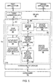
- Figure 5 is a schematic overview of an extension of a structure of Figure 4 to provide a test mechanism in accordance with an embodiment of the present invention.
- a test module 94 is provided including a test driver 96 and a set of intercept routines 98.
- the test module cooperates with the device access infrastructure 90 to form an intercept mechanism for intercepting bus-specific device access function calls.
- the device access infrastructure 90 of Figure 5 is operable to cooperate with the test module for intercepting specified device access calls to inject appropriate responses.
- the device access infrastructure 90 at the device driver interface level can be responsive to a device access call (93) to intercept the call for the selective insertion of faults, whereby the device access call does not pass directly to the device access routines 92 (as represented by the dotted line 93), but instead passes via the intercept routines 98 (as represented by the solid lines 97 and/or 99).
- the device access call may then not result in a device access but may instead result in the return of an emulated device response by virtue of the test harness 94 via the path 97.
- the device access call may indeed result in a device access with an additional pre-specified logical and/or arithmetic operation with fault data prior to being passed to the devices via the paths 99 and 95.
- a user test application 71 can interact with the test driver 96 to configure the intercept routines 98 for specified, or determined corruption of data obtained through the device driver interface access functions.
- the writer of a hardened device driver 84 can produce a set of test scripts which use the test mechanism to demonstrate the resilience of the driver. These scripts can use knowledge of the internals of the driver 84 to generate those types of faults which are most likely to cause problems (e.g. register accesses returning values outside the expected range).
- the test mechanism allows accesses to specific registers to be subject to corruption as well as allowing more random types of corruption to be defined.
- the test scripts can be re-run at a later date when new versions of the driver or the platform become available.
- the test mechanism can be considered to be formed by the combination of the test interface 81 and the intercept mechanism, the latter being formed by the test module 94, which cooperates with the device driver interface mechanism 88.
- the intercept routines then check each use by the device driver 84 of the device access calls to the device access routines to see if this is within specified parameters.
- a count (COUNT 1 - Figure 6) is decremented on each occurrence of a specified device access call. When the count has expired the data read can be operated upon by an operator and operand. This allows a test mechanism to introduce a vast range of different faults.
- the test driver 96 supports a number of I/O control operations ("ioctls") 83, from the test interface 81 which allow error definitions ("errdefs”) to be defined and subsequently managed.
- the test driver is a clone driver, so each time it is opened a separate invocation will be created. Any error definitions created by using I/O control instructions to a given invocation will automatically be deleted when the invocation is closed.
- the test driver 96 is operable to receive a test configuration from a user test application 71 by means of ioctls 95 supplied via an interface in the form of a test interface API 81.
- the device access infrastructure 90 is operable to respond to device access operations to cause the rerouting of the request via the appropriate intercept routines 98 of which there is one for each type of bus access operation. This can be achieved by modifying a table mechanism in the device access infrastructure 90, which would normally be responsive to a bus access operation to identify one or more of the bus specific device access routine(s) 92. However, when in the test mode, the table mechanism is modified to identify intercept routines. In one embodiment of the invention, the intercept routines 98 are managed via the test driver 96.
- a user test application 71 which passes the test configuration mentioned above to the test harness driver 96 can be provided with a testing utility configured to interpret a test script and to detect the response of a driver to the test conditions (faults) inserted by the test module 94. The response can be compared to an expected response set out in the test script. Discrepancies can then be flagged.
- the testing utility can maintain a log of the resulting system messages from the driver under test, annotated with the test configuration active at that time. The testing utility should be able to re-enable the driver concerned to allow for unsupervised testing regimes.
- the test module carries out fault injections based on the error definitions created for that device.
- the timing of the fault injections can be controlled to emulate real faults. This can be achieved by counting particular bus access requests, and then responding to the count value in accordance with a predefined schedule to determine when to inject the faults.
- Separate counters COUNT 1 can be provided for respective access types, device components, etc.
- Faults can be injected into DMA (corrupting data for DMA to/from memory areas defined by device driver interface DMA calls), physical I/O (corrupting data sent/received via device driver interface get and put calls), and interrupts (generating spurious interrupts, losing interrupts, delaying interrupts).
- test field in the test configuration file of the test driver 96 can be set to a list of drivers to tested, or not, depending on the state of a test flag.
- test mechanism can carry out a number of static checks which are controlled by properties in the test configuration file. These can include validation checks that: DMAs into main memory are only carried out into non-shared I/O MMU pages; there are no processor I/O accesses other than those using calls to device driver interface routines, such as ddi_get8(), ddi_put8(), etc., are not made specifying addresses outside the access address range; and calls to DMA synchronization routines are being made correctly.
- FIG. 6 is a schematic representation of the operation of the test harness, or intercept mechanism 94, whereby a ddi (device driver interface) call such as ddi_get8() is intercepted at 950.
- the call is used in a test mode to access a test look-up table 910 provided by the test module 94.
- This table is referenced by the device access infrastructure 90 in response to a device access request.
- the test module thus enables device access calls to be intercepted.
- This test table 910 replaces the standard table used for accessing bus-specific device access routines for normal operation of the system.
- the table 910 identifies an appropriate intercept routine 980 for determining whether a fault is to be injected in response to the access call.
- the decision whether to inject or not will depend on the determined intercept routine 98 which establishes a test pattern on the basis of potential faults which need to be tested, as configured by the test application 71 via the test interface 81 and the device driver 96.
- a counter COUNT I
- a second counter COUNT 2 can be provided where it is determined that the fault needs to be injected for a determined number of times successively to inject the fault.
- a full mapping algorithm could be provided determined injection instances in a sequence.
- Any appropriate encoding technique could be used, such as for example a multi-dimensional array with bits set for fault injections instances and bits not set where fault injection is not required.
- an encoding technique for example run length encoding, could be employed to reduce the size of memory required for the test pattern mapping.
- this step is performed by the intercept routine 980.
- a response with a fault is emulated and returned from the access controller to the device driver.
- the device driver 84 is hardened to deal with the fault which has been injected.
- the device access may alternatively proceed with the fault parameters injected by the intercept routine(s) 98.
- test mechanism Because this process is performed by the test mechanism, it is possible to provide a whole sequence of programmed tests without needing to reboot the system and/or modify the hardware in order to achieve the testing of the device hardening. This can enable testing of the device hardening much more rapid, reliable and complete that would have previously been possible.
- Figure 7 is flow diagram illustrating an overview of the process of intercepting device accesses and injecting errors.
- step S1 an access request to the access controller is intercepted.
- step S2 the injection routine determines whether an error is to be injected for this call. This can be determined, for example, by determining whether a first counter (982 - see Figure 6) for the type of injection routine concerned has underflowed. If it has not underflowed, then no fault is to be injected this time and control passes to step S3, where the count in the counter 982 is decremented. Control is then passed back to step S1.
- a first counter (982 - see Figure 6) for the type of injection routine concerned has underflowed. If it has not underflowed, then no fault is to be injected this time and control passes to step S3, where the count in the counter 982 is decremented. Control is then passed back to step S1.
- step S4 the fault data is injected by the intercept routines.
- the errors are returned to the originator of the device access request to emulate a real error.
- step S5 a check is made as to whether a further injection is required on the next call of the injection routine. This is determined by checking whether a second counter has underflowed.
- step S6 the second counter 984 is reset to a value representative of the number of times the injection is to be repeated for successive calls of the intercept routine concerned.
- the first counter 982 is also reset in step S7 to the number of calls of the intercept routine concerned before the next error injection is to be performed. Control then passes back to step S1.
- step S8 If the second counter has not underflowed, then the count in the second counter 984 is decremented in step S8 before control is passed back to step S1.
- the flow diagram illustrated in Figure 7 is merely one possible way of controlling the interception and injection process.
- the table 960 could form part of the device access infrastructure, rather than being referenced by the device access infrastructure in response to the access request.
- incrementing counters could be used.
- simple counters more complex mapping techniques for determining when and where to inject errors could be employed as mentioned above.
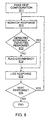
- Figure 8 is a flow diagram summarizing the testing utility functions which may be provided by a user application.
- the user application 99 passes a test configuration to the test driver 96, the test configuration identifying the device(s) to be tested and the parameters of the test.
- a testing utility in the user application monitors a response of a driver to the test conditions inserted by the test mechanism
- the testing utility compares this to an expected result as defined in a test script.
- the testing utility flags any discrepancies.
- the discrepancies could be displayed on a display connected to the graphics adapter of Figure 1, or printed on a printout. Alternatively, they could simply be logged in step S15.
- the testing utility logs the responses with any discrepancies flagged and with the current test configuration.
- step S16 the testing utility returns for a next response.
- the testing utility can be further operable in the event that a fault leads to the system locking to reattach the driver to continue testing.
- a first I/O control operation (HARNESS_ADD_DEF) provides a pointer to a structure for a test harness error definition.
- the structure is identified in Table 1 below:
- error definition (“errdef”) is passed to the driver (but is not actioned until a HARNESS-START I/O control operation is supplied). This returns an error definition handle, or pointer, when successful.
- a handle is a pointer to the appropriate function of entity which provide a compact definition of that function or entity, Multiple concurrent error definitions can be supported referring to the same or different devices. However if multiple faults end up being injected into the same access, the result may be undefined. The fault defined by the "operator” will be injected into the nth qualifying access where n is given by "access_count” and will then continue to be injected for a number of consecutive qualifying accesses defined by the "fail_count” variable.
- access_type can be one of the following types:
- a second I/O control operation deletes a definition (HARNESS_DEL_DEF). This provides a pointer to the item shown in Table 2.
- the errdef_handle field should be the value filled in the errdef_handle field of the error definition structure as returned from a HARNESS_ADD_DEF I/O control operation. This will cancel the specified error definition.
- a third I/O control operation (HARNESS_START) has as an argument a pointer to the item shown in Table 3.
- a fourth I/O control operation has as an argument a pointer to the structure shown in Table 3. This will suspend all error definitions (errdefs) with the specified "name” and "instance". The errdefs can be restarted again by a subsequent HARNESS_START I/O control operation.
- a fifth I/O control operation (HARNESS_BROADCAST) has as an argument a pointer to the structure shown in Table 3. Any processes up that are dormant, or sleeping, in a HARNESS_CHK_STATE_W I/O control operation for an error definition with the specified "name” and "instance” will be woken up.
- a sixth I/O control operation (HARNESS_CLEAR_ACC_CHK) has as an argument a pointer to item shown in Table 3. For all error definitions with the specified "name”/"instance”, if "access_count” and “fail-count” are already zero, then this will set the "acc-chk” field to zero. Any processes up that are sleeping in a HARNESS_CHK_STATE_W I/O control operation for an error definitions with this "name” and "instance” will be woken up.
- a seventh I/O control operation (HARNESS_CLEAR_ERRORS) has as an argument a pointer to item shown in Table 3. For all error definitions with the specified "name” and “instance”, if "access_count” is already zero, then this will set the "acc - chk” and "fail-count” fields to zero. Any processes up that are sleeping in a HARNESS_CHK_STATE_W I/O control operations for an error definition with this "name”/"instance” will be woken up.
- An eighth I/O control operation (HARNESS_CLEAR_ERRDEFS) has as an argument a pointer to item shown in Table 3. For all error definitions with the specified "name” and “instance”, this will set the "acc_chk”, “fail-count” and “access-count” fields to zero. Any processes that are sleeping in a HARNESS_CHK_STATE_W I/O control operation for an error definition with this "name” and “instance” will be woken up.
- a ninth I/O control operation (HARNESS_CHK_STATE) has as an argument a pointer to the item shown in Table 4.
- the errdef handle field should be the value filled in the errdef handle field of the errdef structure shown in Table 1, as returned from a HARNESS_ADD_DEF ioctl. On return from the HARNESS_CHK_STATE I/O control operations, the other fields will be filled in.
- a tenth I/O control operation (HARNESS_CHK_STATE_W) has as an argument a pointer to the item shown in Table 4. If the "access_count" has gone to zero for this error definition and a u4ft - ddi - report_error() has occurred since the last time HARNESS_CHK_STATE_W was called then the I/O control operations will return immediately.
- a twelfth I/O control operation also has a has as an argument a pointer to the item shown in Figure 2. This will turn off debug information for the specified error definition.
- A. thirteenth I/O control operation (HARNESS-GET-HANDLES) has as an argument a pointer to the item shown in Table 5.
- th_define for providing an error definition for the driver test harness.
- th_define(1) allows an error definition (“errdef”) to be specified.
- th_define(1) sleep until either a u4ft_ddi_report_error(9) occurs for the device in question or until th_manage(1) wakes it up. th_define(1) will then output the parameters it was called with and the current state of the error definition to a standard output. If "access count” or “fail count” or “acc-chk” are still non-zero, then th_define(1) will go back to sleep again. When th_define(1) is finally woken up with "access_count”, “fail_count” and “acc_chk” all zero, it will then exit, causing the error definition def to be canceled.
- the debug will be turned on for this error definition, causing information to be displayed by the test driver.
- the fault defined by "operator” will be injected into the nth qualifying access where n is given by “access count” and will then continue to be injected for "fail-count” consecutive qualifying accesses.
- the value in “acc_chk” can be NULL, U4FT_ACC_NO_PIO, U4FT_ACC_NO_DMA or U4FT_ACC_NO_IRQ, and will be ored into the value to be returned from u4ft_ddi_check_access() subsequent to the first fault being injected.
- errors will cease to be injected once "fail count” has gone to zero, "acc_chk” will remain set (until th_define(1) exits, or th_manage(1) is called to clear errors, etc. for this device).
- access_type which can be one of:
- th_manage For managing the test mechanism for a specified device. th_manage(1) acts on the all error definitions ("errdefs") for a specified "name” and “instance”. It supports the following "command" values:-
- the status of the error definitions can be checked by entering:
- the test mechanism is implemented as computer control code, or software, which is stored in the memory 14 of the computer system of Figure 1 and is executed on the processor 12 of Figure 1. It will, however, be appreciated that the test mechanism could be provided on other carrier media, such as a disk, tape, or as electrical, optical, wireless or other signals on a telecommunications medium. The test mechanism could also be implemented, at least on part, by means of special purpose hardware, for example by being implemented in an ASIC.
- the user application can also be implemented as computer control code, or software, which is stored in the memory 14 of the computer system of Figure 1 and is executed on the processor 12 of Figure 1. It will, however, be appreciated that the test mechanism could be provided on other carrier media, such as a disk, tape. or as electrical, optical, wireless or other signals on a telecommunications medium.
- the user application could also be implemented, at least on part, by means of special purpose hardware, for example by being implemented in an ASIC.
Landscapes
- Engineering & Computer Science (AREA)
- Theoretical Computer Science (AREA)
- Computer Hardware Design (AREA)
- Quality & Reliability (AREA)
- Physics & Mathematics (AREA)
- General Engineering & Computer Science (AREA)
- General Physics & Mathematics (AREA)
- Test And Diagnosis Of Digital Computers (AREA)
- Tests Of Electronic Circuits (AREA)
Claims (26)
- Testmechanismus zum Testen des Härtens eines Gerätetreibers, wobei der Testmechanismus einen Abfangmechanismus (94) aufweist, der so betreibbar ist, daß er Zugriffsaufrufe auf ein Gerät von einem sich im Test befindlichen Gerätetreiber abfängt, und mit einer Schnittstelle (88), die so betreibbar ist, daß sie den Abfangmechanismus derart konfiguriert, daß in Reaktion auf Gerätezugriffsaufrufe Fehler entsprechend einem vorbestimmten Testmuster injiziert werden.
- Testmechanismus nach Anspruch 1, wobei der Abfangmechanismus eine Mehrzahl von Abfangroutinen (98) aufweist.
- Testmechanismus nach Anspruch 2, wobei jede Abfangroutine für einen gegebenen Typ von Gerätezugriffsaufruf vorgesehen ist.
- Testmechanismus nach Anspruch 2 oder 3, mit einem Zuordnungsmechanismus zum Zuordnen von Gerätezugriffsaufrufen zu Abfangroutinen.
- Testmechanismus nach Anspruch 4, wobei der Zuordnungsmechanismus eine Nachschlagetabelle aufweist.
- Testmechanismus nach einem der vorstehenden Ansprüche, wobei der Abfangmechanismus so betreibbar ist, daß er Gerätezugriffsaufrufe überwacht, um zu bestimmen, wann ein Fehler einzubringen ist.
- Testmechanismus nach einem der vorstehenden Ansprüche mit einem Zähler (982), der zumindest einem vorbestimmten Typ von Gerätezugriffsaufruf zugeordnet ist, wobei der Abfangmechanismus (94) so betreibbar ist, daß er den Zähler überwacht, der für jeden Gerätezugriffsaufruf dieses Typs modifiziert wird und so betreibbar ist, daß er einen Fehler in Reaktion auf eine festgestellte Zählung des Zählers einbringt.
- Testmechanismus nach Anspruch 8 mit einem Zähler (984), um eine Anzahl von Malen zu bestimmen, um welche ein Fehler für aufeinanderfolgende Gerätezugriffsaufrufe des vorbestimmten Typs eingebracht werden soll.
- Testmechanismus nach Anspruch 3 oder einem der davon abhängigen Ansprüche 4 bis 7, wobei jeder Typ eines Gerätezugriffaufrufs separat überwacht wird.
- Testmechanismus nach einem der vorstehenden Ansprüche, wobei eine Gerätezugriffsinfrastruktur auf einen Gerätezugriffsaufruf so reagiert, daß sie den Aufruf für die wahlweise Einfügung von Fehlern abfängt und der Abfangmechanismus so betreibbar ist, daß er eine emulierte Geräteantwort zurückliefert.
- Testmechanismus nach einem der vorstehenden Ansprüche, wobei eine Zugriffsinfrastruktur für das Gerät auf einen Gerätezugriffsaufruf so reagiert, daß sie den Aufruf abfängt und der Abfangmechanismus so betreibbar ist, daß er eine wahlweise Einfügung von Fehlern bereitstellt, bevor der Gerätezugriff bewirkt wird.
- Testmechanismus nach Anspruch 11, wobei der Abfangmechanismus mit Daten eines Gerätezugriffsaufrufs mit bestimmtem Operator und Operanden arbeitet.
- Testmechanismus nach Anspruch 6, wobei die Schnittstelle so betreibbar ist, daß sie den Abfangmechanismus so konfiguriert, daß er bestimmt, wann der Abfangmechanismus einen Fehler einbringt.
- Testmechanismus nach einem der vorstehenden Ansprüche, mit einem Computerprogrammcode, der so betreibbar ist, daß er den Abfangmechanismus und die Schnittstelle bildet.
- Testmechanismus nach Anspruch 14 auf einem Trägermedium.
- Testmechanismus nach einem der vorstehenden Ansprüche, wobei die Schnittstelle eine Anwenderprogrammschnittstelle aufweist, die auf eine Testanwendung reagiert, um ein Testmuster festzulegen.
- Testanwendung auf einem Trägermedium für einen Testmechanismus nach Anspruch 14, wobei die Anwendung Computercode aufweist, der so ausgestaltet ist, daß er in folgender Weise betreibbar ist,um die Schnittstelle mit einer Testkonfiguration zu versehen,die Reaktion eines Gerätetreibers auf einen Testzustand, der durch den Abfangmechanismus eingefügt wurde, zu erfassen,die erfaßte Reaktion mit einer in einem Testskript dargelegten, erwarteten Reaktion zu vergleichen, undUnterschiede zwischen der erfaßten Reaktion und der erwarteten Reaktion zu identifizieren bzw. zu kennzeichnen.
- Testanwendung nach Anspruch 17, wobei die Testanwendung Computercode aufweist, der so ausgestaltet ist, daß er in der Weise betreibbar ist, daß er eine Aufzeichnung der erfaßten Reaktionen aufrechterhält.
- Computer mit einem Gerätetreiber für den Zugriff auf eine I/O-Einrichtung und mit einem Testmechanismus nach einem der Ansprüche 1 bis 16 zum Testen der Härtung von Gerätetreibern.
- Verfahren zum Testen des Härtens eines Gerätetreibers, wobei das Verfahren das Abfangen von Zugriffsaufrufen auf den Gerätetreiber von dem Gerätetreiber aufweist und das Injizieren eines Fehlers in den Gerätetreiberzugriff entsprechend einem gewünschten Testmuster.
- Verfahren nach Anspruch 20, welches das Zuordnen des Gerätezugriffsaufrufs zu zumindest einer Abfangroutine für das Handhaben des Gerätezugriffsaufrufs aufweist.
- Verfahren nach Anspruch 21, welches das Zuordnen eines Gerätezugriffsaufrufs an eine Abfangroutine entsprechend einem Typ des Gerätezugriffsaufrufs aufweist.
- Verfahren nach Anspruch 20, welches das Überwachen des Gerätezugriffsaufrufs aufweist, um zu bestimmen, wann ein Fehler einzuführen ist.
- Verfahren nach Anspruch 23, welches das Modifizieren einer Zählung für einen Gerätezugriffsaufruf eines gegebenen Typs sowie das Injizieren eines Fehlers in Reaktion darauf aufweist, daß eine vorbestimmte Zahl erreicht worden ist.
- Verfahren nach Anspruch 24, welches das getrennte Überwachen jedes Typs von Aufruf aufweist.
- Verfahren nach Anspruch 24, welches weiterhin einen Schritt des Überwachens für eine Anzahl von Malen aufweist, um welche der Fehler in die Sequenz eingeführt werden soll.
Applications Claiming Priority (3)
| Application Number | Priority Date | Filing Date | Title |
|---|---|---|---|
| US97468 | 1979-11-26 | ||
| US09/097,468 US6971048B1 (en) | 1998-06-15 | 1998-06-15 | Testing device driver hardening |
| PCT/US1999/013069 WO1999066398A1 (en) | 1998-06-15 | 1999-06-09 | Testing device driver reliability |
Publications (2)
| Publication Number | Publication Date |
|---|---|
| EP1086423A1 EP1086423A1 (de) | 2001-03-28 |
| EP1086423B1 true EP1086423B1 (de) | 2002-10-23 |
Family
ID=22263526
Family Applications (1)
| Application Number | Title | Priority Date | Filing Date |
|---|---|---|---|
| EP99927418A Expired - Lifetime EP1086423B1 (de) | 1998-06-15 | 1999-06-09 | Prüfung der funktionsfähigkeit eines gerätetreibers |
Country Status (4)
| Country | Link |
|---|---|
| US (1) | US6971048B1 (de) |
| EP (1) | EP1086423B1 (de) |
| DE (1) | DE69903629T2 (de) |
| WO (1) | WO1999066398A1 (de) |
Families Citing this family (41)
| Publication number | Priority date | Publication date | Assignee | Title |
|---|---|---|---|---|
| US7111307B1 (en) * | 1999-11-23 | 2006-09-19 | Microsoft Corporation | Method and system for monitoring and verifying software drivers using system resources including memory allocation and access |
| US7530076B2 (en) * | 2001-03-23 | 2009-05-05 | S2 Technologies, Inc. | Dynamic interception of calls by a target device |
| US20030061292A1 (en) * | 2001-03-23 | 2003-03-27 | Mark Underseth | System and method for providing an interface for com-compliant applications to communicate with embedded systems |
| US6901539B2 (en) * | 2002-04-10 | 2005-05-31 | Microsoft Corporation | ACPI name space validation |
| US7089456B2 (en) * | 2002-06-03 | 2006-08-08 | Honeywell International, Inc | Error response test system and method using test mask variable |
| TW559672B (en) * | 2002-07-24 | 2003-11-01 | Via Tech Inc | Testing method of chip configuration setup |
| US7469343B2 (en) * | 2003-05-02 | 2008-12-23 | Microsoft Corporation | Dynamic substitution of USB data for on-the-fly encryption/decryption |
| US7321951B2 (en) * | 2003-11-17 | 2008-01-22 | Micron Technology, Inc. | Method for testing flash memory power loss recovery |
| US7877733B2 (en) * | 2004-07-14 | 2011-01-25 | Oracle International Corporation | Failure test framework |
| US20060126799A1 (en) * | 2004-12-15 | 2006-06-15 | Microsoft Corporation | Fault injection |
| US20060126800A1 (en) * | 2004-12-15 | 2006-06-15 | Microsoft Corporation | Fault injection object |
| US7404107B2 (en) * | 2004-12-15 | 2008-07-22 | Microsoft Corporation | Fault injection selection |
| US7849364B2 (en) * | 2005-03-01 | 2010-12-07 | Microsoft Corporation | Kernel-mode in-flight recorder tracing mechanism |
| US7536605B2 (en) * | 2005-05-25 | 2009-05-19 | Alcatel-Lucent Usa Inc. | Injection of software faults into an operational system |
| US7487327B1 (en) | 2005-06-01 | 2009-02-03 | Sun Microsystems, Inc. | Processor and method for device-specific memory address translation |
| US20070038982A1 (en) | 2005-08-11 | 2007-02-15 | International Business Machines Corporation | Method and process to automatically perform test builds or translated files for a software product |
| US20070043956A1 (en) * | 2005-08-19 | 2007-02-22 | Microsoft Corporation | System and methods that facilitate third party code test development |
| US7539904B2 (en) * | 2005-11-07 | 2009-05-26 | International Business Machines Corporation | Quantitative measurement of the autonomic capabilities of computing systems |
| US7669095B2 (en) * | 2006-02-01 | 2010-02-23 | International Business Machines Corporation | Methods and apparatus for error injection |
| US20070288937A1 (en) * | 2006-05-08 | 2007-12-13 | Microsoft Corporation | Virtual Device Driver |
| US8756569B2 (en) * | 2007-12-17 | 2014-06-17 | International Business Machines Corporation | Deterministic pseudo-random fault event recordation and injection tool |
| US9298568B2 (en) * | 2008-02-07 | 2016-03-29 | International Business Machines Corporation | Method and apparatus for device driver state storage during diagnostic phase |
| US8793662B2 (en) * | 2008-03-25 | 2014-07-29 | Microsoft Corporation | Runtime code hooking for print driver and functionality testing |
| US8826238B2 (en) | 2009-01-22 | 2014-09-02 | Microsoft Corporation | Per group verification |
| US8418012B2 (en) | 2010-09-21 | 2013-04-09 | Ansaldo Sts Usa, Inc. | Method of analyzing the safety of a device employing on target hardware description language based fault injection |
| US9208064B2 (en) * | 2011-08-09 | 2015-12-08 | Red Hat, Inc. | Declarative testing using dependency injection |
| US9239776B2 (en) | 2012-02-09 | 2016-01-19 | Vmware, Inc. | Systems and methods to simulate storage |
| US9830287B2 (en) | 2015-02-24 | 2017-11-28 | Red Hat Israel, Ltd. | Determination of a device function asserting a detected spurious interrupt |
| US9824000B1 (en) * | 2015-10-21 | 2017-11-21 | Amazon Technologies, Inc. | Testing calling code dynamically with random error injection based on user-specified configuration |
| US10146653B2 (en) * | 2016-09-21 | 2018-12-04 | Dell Products, L.P. | Automated system-level failure and recovery |
| US10990457B2 (en) | 2017-06-28 | 2021-04-27 | Apple Inc. | Interposition |
| JP2019191942A (ja) * | 2018-04-25 | 2019-10-31 | 株式会社デンソーテン | 制御装置および機能検査方法 |
| US10922249B2 (en) * | 2019-01-15 | 2021-02-16 | Microsoft Technology Licensing, Llc | Input/output control code filter |
| US11093378B2 (en) | 2019-06-27 | 2021-08-17 | Capital One Services, Llc | Testing agent for application dependency discovery, reporting, and management tool |
| EP3991030B1 (de) * | 2019-06-27 | 2025-12-17 | Capital One Services, LLC | Bestimmung von problemabhängigkeiten in der anwendungsabhängkeitentdeckung, berichterstattung und verwaltungswerkzeug |
| US10915428B2 (en) * | 2019-06-27 | 2021-02-09 | Capital One Services, Llc | Intelligent services and training agent for application dependency discovery, reporting, and management tool |
| US10642719B1 (en) | 2019-06-27 | 2020-05-05 | Capital One Services, Llc | Intelligent services for application dependency discovery, reporting, and management tool |
| US10747544B1 (en) | 2019-06-27 | 2020-08-18 | Capital One Services, Llc | Dependency analyzer in application dependency discovery, reporting, and management tool |
| US11354222B2 (en) | 2019-06-27 | 2022-06-07 | Capital One Services, Llc | Discovery crawler for application dependency discovery, reporting, and management tool |
| EP3848763B1 (de) * | 2020-01-08 | 2022-12-21 | Elektrobit Automotive GmbH | Qualifizierung eines gerätetreibers für ein gerät |
| CN113407394B (zh) * | 2021-05-31 | 2023-03-28 | 浪潮电子信息产业股份有限公司 | 一种服务器ras功能测试的方法、装置、设备和介质 |
Family Cites Families (6)
| Publication number | Priority date | Publication date | Assignee | Title |
|---|---|---|---|---|
| US4312066A (en) * | 1979-12-28 | 1982-01-19 | International Business Machines Corporation | Diagnostic/debug machine architecture |
| US5001712A (en) * | 1988-10-17 | 1991-03-19 | Unisys Corporation | Diagnostic error injection for a synchronous bus system |
| US5193178A (en) * | 1990-10-31 | 1993-03-09 | International Business Machines Corporation | Self-testing probe system to reveal software errors |
| US5634022A (en) | 1992-03-06 | 1997-05-27 | International Business Machines Corporation | Multi-media computer diagnostic system |
| GB2268817B (en) | 1992-07-17 | 1996-05-01 | Integrated Micro Products Ltd | A fault-tolerant computer system |
| US5864653A (en) * | 1996-12-31 | 1999-01-26 | Compaq Computer Corporation | PCI hot spare capability for failed components |
-
1998
- 1998-06-15 US US09/097,468 patent/US6971048B1/en not_active Expired - Lifetime
-
1999
- 1999-06-09 WO PCT/US1999/013069 patent/WO1999066398A1/en not_active Ceased
- 1999-06-09 EP EP99927418A patent/EP1086423B1/de not_active Expired - Lifetime
- 1999-06-09 DE DE69903629T patent/DE69903629T2/de not_active Expired - Fee Related
Also Published As
| Publication number | Publication date |
|---|---|
| WO1999066398A9 (en) | 2000-04-06 |
| DE69903629D1 (de) | 2002-11-28 |
| WO1999066398A1 (en) | 1999-12-23 |
| DE69903629T2 (de) | 2003-07-31 |
| US6971048B1 (en) | 2005-11-29 |
| EP1086423A1 (de) | 2001-03-28 |
Similar Documents
| Publication | Publication Date | Title |
|---|---|---|
| US6971048B1 (en) | Testing device driver hardening | |
| US7536605B2 (en) | Injection of software faults into an operational system | |
| US8230399B2 (en) | Method for system call interception in user space | |
| EP0814404B1 (de) | Vorrichtung zur Programmfehlerbeseitigung | |
| US5630049A (en) | Method and apparatus for testing software on a computer network | |
| US5671352A (en) | Error injection to a behavioral model | |
| US6047124A (en) | System and method for tracing device drivers using a computer | |
| US7225428B1 (en) | Robust software library wrapper method and apparatus | |
| Buchacker et al. | Framework for Testing the Fault-Tolerance of Systems Including OS and Network Aspects. | |
| James | PC interfacing and data acquisition: techniques for measurement, instrumentation and control | |
| US6393493B1 (en) | System and method for optimizing serial USB device reads using virtual FIFO techniques | |
| JP2004519041A (ja) | 効率的なデータロード及びアンロードのために統合されるパケット基準のプロトコル論理を用いるハードウェア支援設計検証システム | |
| US7793160B1 (en) | Systems and methods for tracing errors | |
| US5307482A (en) | Computer, non-maskable interrupt trace routine override | |
| US7536694B2 (en) | Exception handling in a multiprocessor system | |
| US6374399B1 (en) | Apparatus and method for providing list and read list capability for a host computer system | |
| CN114817063A (zh) | 模拟测试方法、设备及存储介质 | |
| Baldini et al. | " BOND": An interposition agents based fault injector for Windows NT | |
| US7779407B2 (en) | Computer-hardware, life-extension apparatus and method | |
| CN119598921A (zh) | 用于芯片设计方案的验证方法及验证装置、电子设备 | |
| US6141635A (en) | Method of diagnosing faults in an emulated computer system via a heterogeneous diagnostic program | |
| CN116776783B (zh) | 一种模拟寄存器读写的白盒验证方法、系统、设备及介质 | |
| Höxer et al. | Umlinux-a tool for testing a linux system’s fault tolerance | |
| US7139954B1 (en) | Method and apparatus for testing a computing device with memory using test program code | |
| CN113760692A (zh) | 日志获取方法、装置及设备 |
Legal Events
| Date | Code | Title | Description |
|---|---|---|---|
| PUAI | Public reference made under article 153(3) epc to a published international application that has entered the european phase |
Free format text: ORIGINAL CODE: 0009012 |
|
| 17P | Request for examination filed |
Effective date: 20001220 |
|
| AK | Designated contracting states |
Kind code of ref document: A1 Designated state(s): DE GB IE |
|
| RIN1 | Information on inventor provided before grant (corrected) |
Inventor name: RADLEY, EDWARD JAMES Inventor name: HANSON, STEPHEN, RICHARD |
|
| GRAG | Despatch of communication of intention to grant |
Free format text: ORIGINAL CODE: EPIDOS AGRA |
|
| 17Q | First examination report despatched |
Effective date: 20020129 |
|
| GRAG | Despatch of communication of intention to grant |
Free format text: ORIGINAL CODE: EPIDOS AGRA |
|
| GRAH | Despatch of communication of intention to grant a patent |
Free format text: ORIGINAL CODE: EPIDOS IGRA |
|
| GRAH | Despatch of communication of intention to grant a patent |
Free format text: ORIGINAL CODE: EPIDOS IGRA |
|
| GRAA | (expected) grant |
Free format text: ORIGINAL CODE: 0009210 |
|
| AK | Designated contracting states |
Kind code of ref document: B1 Designated state(s): DE GB IE |
|
| REG | Reference to a national code |
Ref country code: GB Ref legal event code: FG4D |
|
| REG | Reference to a national code |
Ref country code: IE Ref legal event code: FG4D |
|
| REF | Corresponds to: |
Ref document number: 69903629 Country of ref document: DE Date of ref document: 20021128 |
|
| PLBE | No opposition filed within time limit |
Free format text: ORIGINAL CODE: 0009261 |
|
| STAA | Information on the status of an ep patent application or granted ep patent |
Free format text: STATUS: NO OPPOSITION FILED WITHIN TIME LIMIT |
|
| 26N | No opposition filed |
Effective date: 20030724 |
|
| PGFP | Annual fee paid to national office [announced via postgrant information from national office to epo] |
Ref country code: IE Payment date: 20040611 Year of fee payment: 6 |
|
| PG25 | Lapsed in a contracting state [announced via postgrant information from national office to epo] |
Ref country code: IE Free format text: LAPSE BECAUSE OF NON-PAYMENT OF DUE FEES Effective date: 20050609 |
|
| REG | Reference to a national code |
Ref country code: IE Ref legal event code: MM4A |
|
| PGFP | Annual fee paid to national office [announced via postgrant information from national office to epo] |
Ref country code: DE Payment date: 20060601 Year of fee payment: 8 |
|
| PGFP | Annual fee paid to national office [announced via postgrant information from national office to epo] |
Ref country code: GB Payment date: 20060607 Year of fee payment: 8 |
|
| GBPC | Gb: european patent ceased through non-payment of renewal fee |
Effective date: 20070609 |
|
| PG25 | Lapsed in a contracting state [announced via postgrant information from national office to epo] |
Ref country code: DE Free format text: LAPSE BECAUSE OF NON-PAYMENT OF DUE FEES Effective date: 20080101 |
|
| PG25 | Lapsed in a contracting state [announced via postgrant information from national office to epo] |
Ref country code: GB Free format text: LAPSE BECAUSE OF NON-PAYMENT OF DUE FEES Effective date: 20070609 |