EP1086623B1 - Pondoir pour volailles, avec au moins une unité de pondoir - Google Patents
Pondoir pour volailles, avec au moins une unité de pondoir Download PDFInfo
- Publication number
- EP1086623B1 EP1086623B1 EP00114585A EP00114585A EP1086623B1 EP 1086623 B1 EP1086623 B1 EP 1086623B1 EP 00114585 A EP00114585 A EP 00114585A EP 00114585 A EP00114585 A EP 00114585A EP 1086623 B1 EP1086623 B1 EP 1086623B1
- Authority
- EP
- European Patent Office
- Prior art keywords
- housing
- laying
- arrangement according
- floor
- nest arrangement
- Prior art date
- Legal status (The legal status is an assumption and is not a legal conclusion. Google has not performed a legal analysis and makes no representation as to the accuracy of the status listed.)
- Expired - Lifetime
Links
- 244000144977 poultry Species 0.000 title claims abstract description 21
- 235000013601 eggs Nutrition 0.000 claims abstract description 50
- 238000005096 rolling process Methods 0.000 description 7
- 241001465754 Metazoa Species 0.000 description 6
- 230000005540 biological transmission Effects 0.000 description 5
- 230000033001 locomotion Effects 0.000 description 5
- 230000006378 damage Effects 0.000 description 4
- 210000000056 organ Anatomy 0.000 description 4
- 208000027418 Wounds and injury Diseases 0.000 description 3
- 230000017448 oviposition Effects 0.000 description 3
- 210000003746 feather Anatomy 0.000 description 2
- 208000014674 injury Diseases 0.000 description 2
- 238000004519 manufacturing process Methods 0.000 description 2
- 230000002411 adverse Effects 0.000 description 1
- 230000015572 biosynthetic process Effects 0.000 description 1
- 235000013305 food Nutrition 0.000 description 1
- 230000005484 gravity Effects 0.000 description 1
- 230000003993 interaction Effects 0.000 description 1
- 235000021190 leftovers Nutrition 0.000 description 1
- KNVAYBMMCPLDOZ-UHFFFAOYSA-N propan-2-yl 12-hydroxyoctadecanoate Chemical compound CCCCCCC(O)CCCCCCCCCCC(=O)OC(C)C KNVAYBMMCPLDOZ-UHFFFAOYSA-N 0.000 description 1
- 230000001141 propulsive effect Effects 0.000 description 1
- 230000002441 reversible effect Effects 0.000 description 1
- 230000035939 shock Effects 0.000 description 1
Images


Classifications
-
- A—HUMAN NECESSITIES
- A01—AGRICULTURE; FORESTRY; ANIMAL HUSBANDRY; HUNTING; TRAPPING; FISHING
- A01K—ANIMAL HUSBANDRY; AVICULTURE; APICULTURE; PISCICULTURE; FISHING; REARING OR BREEDING ANIMALS, NOT OTHERWISE PROVIDED FOR; NEW BREEDS OF ANIMALS
- A01K31/00—Housing birds
- A01K31/14—Nest-boxes, e.g. for singing birds or the like
- A01K31/16—Laying nests for poultry; Egg collecting
Definitions
- the invention relates to a nesting arrangement for Poultry comprising at least one housing at least one passage opening for the poultry having housing walls and with at least one Case bottom and comprising one on a case bottom edge along-removed device for laying eggs, the housing bottom is inclined towards the Has removal device.
- Laying nest arrangements of this type are particularly in Large barn systems for poultry, for example for Laying hens installed in an industrial way of eggs to be laid by the poultry and evacuate.
- poultry With the housing of the nesting arrangement poultry becomes a place to lay eggs provided.
- the housing forms, for example an enclosed space into which the poultry goes through at least one passage opening in one of the walls of the Housing can get.
- On the bottom of this case laid eggs roll due to their shape and inclination the bottom of the case down.
- You roll in the removal device because of the inclination of the housing base in the direction of the removal device runs.
- the removal device is, for example a conveyor belt that rolls eggs from the bottom of the case picks up and transported out of the nesting arrangement.
- the case back is often caused by excrement of the Poultry, leftovers, feathers and the like dirty, so that if the inclination of the Case bottom eggs on the case bottom due to its uneven produced by the dirt Surface remain. So that the eggs by means of theirs Gravity causes the bumps to roll can overcome and on the removal device roll, is a known nesting arrangements greater inclination of the case base is set. See e.g. the document FR-A-2365951 disadvantageous is that the eggs due to the greater inclination of the Roll the case back down at a higher speed. This higher speed arises especially when if the taxiway is due to a wide or deep trained housing base is relatively long.
- the invention has for its object a laying nest arrangement to show the genus mentioned at the outset ensures a reduction in the reject rate.
- the Housing base formed from at least two base plates is mutually parallel to the longitudinal extent the removal device aligned and in the plane pivoting axis of the housing base are, and that at least one is a separate pivot each bottom plate effecting pivot member provided is.
- Case bottom not in one piece, but in sections formed by base plates.
- the housing base can be in two base plates be divided, which lie in one plane and thereby overall form the housing base. Both base plates can be swiveled towards each other, i.e. a base plate can be pivoted towards the other base plate.
- the pivot axis lies in the plane of the housing base. This ensures that even when swiveling the bottom plates to each other still a case bottom remains educated. This is characterized by that it consists of two sections with different inclinations or inclinations towards the removal device can exist.
- one base plate is swiveled towards the other, then shows a different inclination towards the environment of the Bottom of the housing, in particular with regard to the removal device, on.
- the slope can be steeper be, so that possibly already on this base plate Broken eggs brought to roll again become.
- the other base plate can be one have less inclination.
- Can on this base plate roll the eggs from the base plate with a greater inclination, which is advantageously achieved that the eggs on this Roll out the base plate due to the lower inclination and not be accelerated further, as is the case with a Case bottom with consistently greater inclination is.
- This quasi braking is caused by the friction of the Eggs on this bottom plate, the rolling resistance, the one lower propulsive force due to the lower inclination counteracts. It is thus advantageously prevented that the rolling eggs have such a rolling speed achieve that when these eggs collide with obstacles or other eggs to mechanical would damage their shells.
- this base plate can be independent of "the another base plate with a swivel organ steeper be employed. This increases the Inclination of this base plate, but not at the same time increasing the inclination of the first base plate, but for example afterwards.
- the inclination is increased in each case of mutually separate sections of the housing base, the base plates, in the direction of the removal device.
- the inclinations are preferably increased in a time sequence, so that rolling eggs like be moved on a wave.
- the Bottom plate made steeper, that of the removal device most distant.
- this can Base plate must always be set steeply.
- the eggs can then be placed on a base plate roll that is closer to the removal device.
- Another advantage of the laying nest arrangement according to the invention is that because of the controlled Rolling movements of the eggs is achievable that one Casing base with a larger width, i.e. Depth towards the removal device can be produced.
- This larger width would be with known laying nest arrangements cause the eggs to one over the long taxiway experience high speed.
- Lay nest arrangement advantageously does not occur high Speed of the eggs on because they pass through the differently inclined base plates of the housing base are braked in the course of the taxiway.
- the larger width can advantageously be larger Number of laying hens at the same time in the Laying nest arrangement can be installed, whereby with a major advantage is an increase in egg production is achievable.
- the separate base plates of the housing base can be in be arranged freely next to each other on one level. It is but also possible to go through the floor panels with each other at least one joint, for example a hinge connect so that their mutual pivoting continues is manufactured and by the hinge or by the Hinges or similar joint means is guided.
- Each floor plate can be swiveled separately be that for each base plate a single swivel member is available.
- a swivel member for example each serve a lever or a cylinder that separately on a base plate in its pivoting effecting attack.
- These swivel members can for example, starting from the base plate that the The most distant way to remove the eggs is are operated one after the other, so that the Inclinations of the base plates can be increased.
- alternative can be provided that for two adjacent to each other Base plates a common swivel member is provided. The separate pivoting can also be carried out with a pivoting member of these two bottom plates can be achieved if that Swivel organ first on a base plate in your Attack changing way attacks and subsequent attacks accordingly on the second base plate.
- the housing base is mounted tiltable about a tilt axis is that the tilt axis one of a passage opening Approximate edge of the housing base is assigned and that a tilt drive is provided.
- This tilt axis is assigned to the edge of the housing base, which is the Passage opening or several passage openings in a housing wall is approximated. Will the case back is tilted about this tilt axis, so the housing bottom of inside against the passage openings. This are thereby closed, with the advantage that in this position of the housing base no access for the Poultry is given in the laying nest arrangement.
- the inventive design of the housing base is prevented with particular advantage that on the Eggs left lying at the bottom of the housing by tilting the Casing flung out of the nesting arrangement become.
- the inventive training of Housing bottom advantageously allows before tilting the Housing base on the base plates of the housing base eggs that have been left lying gently in the manner described to move to the removal device.
- the Invention includes the tilt drive on the side Drawbar passed by the bottom of the housing, the free end of which is arranged below the housing base and on which the Swivel member, for example, for two adjacent Floor plates is arranged.
- the swivel members in the Integrated tilt drive By pressing the Tilt drive can thereby also actuate the Swivel members and a tilting of the housing base take place.
- the constructive structure is based on the summary both motion drives and the associated Saving of components simplified.
- the housing of the laying nest arrangement according to the invention is preferably on arranged a frame so that under the Housing floor space for the arrangement of a Swivel organ is present.
- the swivel member is on free end of the drawbar below the bottom of the housing arranged, which ensures in an advantageous manner is that the surface of the case back, that for the Poultry is accessible, free from components of the Swivel organ is. These are below the bottom of the case arranged and grip the bottom of the case, namely on its individual floor slabs. With the Drawbar becomes a pulling force on the swivel member exercised, which is directed upwards. About these Tension is a total tilt of the case bottom causes, while at the same time making it possible for the individual Bottom plates of the housing base one after the other larger inclinations are brought.
- the swivel member is the Invention formed as an approximately triangular platen and at the free end of the drawbar below the Casing hinged, one side of the triangular support plate as a support edge for two Base plates is formed.
- the Pull rod up the platen due to its Linkage on the drawbar also moved upwards. It attacks the bottom of the case from below.
- Due to their pivotable linkage on the drawbar can the platen first in a Are swivel position in which their contact edge on a of the two base plates. This bottom plate is from the egg removal device removed than the other bottom plate. It is preferred steeper before moving the drawbar hired, which is why eggs from this base plate on the can roll other base plate.
- lifting the Drawbar grips the support edge of the triangular one Support plate also on the other base plate and increases their inclination in relation to the level of Transporting device. The one on this bottom plate Eggs lying on it can be from this Unroll the transport device.
- the contact edge of the approximately triangular platen starting from the center of her Longitudinal extent has bevels on both sides.
- the Bevels occur with the undersides of the floor slabs in close interaction. Because of the swiveling the triangular platen and due to the Bevels ensure that first a Apply one of the bevelled side of the support edge one base plate occurs before the other bevelled side of the support edge to the neighboring Base plate is created.
- the bevels are there each continuously trained so that everyone bevelled support edge portion just formed is.
- the tilt drive includes a pivot lever the free end of the pull rod is pivotable is articulated and at its other free end Power transmission means attacks.
- the power transmission medium is the swivel lever in one Swiveling movement, in the course of which the free end the swivel lever on which the drawbar is articulated, is moved upwards.
- the power transmission medium is, for example, one wound on a shaft Belt.
- the shaft can be driven in by a suitable drive reversible rotary movements are offset, whereupon the Belt is wound onto the shaft or from the shaft is handled. This causes the Pivot lever.
- Other power transmission means, such as Chains can also be used.
- a housing wall of the housing at least one Has passage opening for the poultry, and that the Removal device for the eggs laid on the this housing wall opposite side of the housing base is arranged.
- This arrangement is the Casing base from the passage opening for the poultry starting downwards inclined to the removal device.
- the removal device is thereby, for example, inside arranged of the housing.
- the Kloake points into the nesting arrangement and is from outside, in particular in front of the passage opening other animals cannot be reached. by virtue of the inward towards the removal device aligned inclination of the case back is an egg laying animal with the chest raised on the case back arranged. This arrangement also advantageously reduces Injuries to the animal.
- the removal device of the invention Laying nest arrangement is preferably a known one Conveyor belt. This can be done by an appropriate Length training on several housing bottoms of several Be guided along the housing.
- housings can be combined into one housing group be, the respectively associated pivot lever of Tilt drives with a common shaft in the operative connection stand.
- Housings can be separated from one another by rear walls.
- a Rear wall can, for example, above the removal device be arranged for the eggs. The Arrangement has the advantage that the rear wall prevents that animals step on the removal device and this pollute.
- a housing group can also be constructed in several days. Finally, it can be provided that on the A mat is placed on the case back. That mat covers the separate base plates and the one between the Floor plates formed distance, especially gap.
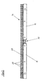
- the nesting arrangement in Fig. 1 has several in two Rows of housings 1 arranged side by side. Each four housings 1 are arranged in a row. Each Housing 1 is by housing side walls 2, 3 and one Housing roof 4 limited. Between each other opposite housings 1 arranged Housing rear walls 31 are not shown.
- the in Fig. 1st Housing 1 shown on the right are without the housing walls 3 and the housing roof 4 drawn.
- the housing roof 4, arranged on each side of the housing roof ridge 5 is divided into two.
- a housing roof section 6 is over Hinges 7 pivotable on the housing roof section 8 hinged.
- the housing wall 3 has through openings 9 for the Poultry on. All housing 1 are on one Frame 10 arranged.
- the frame 10 has erectable on a floor, not shown Legs 11 and frame profiles 12 connected to them on. The housings 1 rest on the frame profiles 12.
- housings 1 face each other in pairs.
- conveyor belts 13 between the housings 1 arranged as removal devices for laid eggs.
- a shaft 26 is located above the conveyor belts 13 arranged, it runs parallel to the conveying direction of the Conveyor belts 13.
- the conveyor belts 13 are housing bottoms 14 on both sides of the Assigned to housing 1.
- the housing base 14 consists of two base plates 15. Die Base plates 15 lie side by side so that they Form housing bottom 14 closed. Both base plates 15 are pivotable to each other about a pivot axis. The Swivel axis is between the facing Side edges of the bottom plates 15 arranged so that the one base plate 15 relative to the other base plate 15 is pivotable without the formation of a closed housing base 14 is lifted.
- a pull rod 16 is assigned to the housing base 14.
- the Drawbar 16 is arranged next to the housing base 14, From Fig. 1 it can be seen that each housing base 14 in Area of both end edges of its base plates 15 each a pull rod 16 is assigned.
- the free end of the Drawbar 16 is below the housing base 14 arranged.
- At this end is a triangular one Support plate 17 is pivotable about a pivot axis 18 hinged.
- the support plate 17 has a support edge 19 on the undersides of both base plates 15 can be created.
- the platen 17 is on the tie rod 16 hinged such that a triangular corner in the direction the free end of the pull rod 16 shows.
- the support edge 19 is arranged on the side of the platen 17, the opposite this corner.
- Fig. 2 it is shown that the support edge 19 to the Bottom plate 15, which is further away from the conveyor belt 13, is created.
- the Contact edge 19 On the second base plate 15 is the Contact edge 19 not applied.
- the level of the conveyor belt 13 more distant bottom plate 15 is steeper to this level employed than the other base plate 15.
- the different inclinations of the base plates 15 result on the one hand from the angled position of the support plate 17 with respect to the longitudinal extension of the pull rod 16. This ensures that the bottom plate 15, which is further away from the conveyor belt 13 Area of the contact edge 19 on this base plate 15 is created, while that of the other base plate 15 assigned area of the contact edge 19 to this Base plate 15 has not yet been created.
- the other end of the pull rod facing away from the support plate 17 16 is at the free end of a pivot lever 20th hinged about an axis 21.
- the swivel lever 20 is in the middle of his Longitudinal extent on a support shoulder 22 pivotable hung up.
- the support shoulder 22 is by the Housing wall 2 formed, the corresponding one Has cut.
- an arcuate cutout 23 is also introduced, whose imaginary center with the swivel axis of the Swivel lever 20 coincides.
- Through the cutout 23 is a bolt 24 providing the pivot axis 21 passed.
- the bolt 24 connects on both sides of the Housing wall 2 extending sections of the pivot lever 20th together.
- the pivot lever 20 engages it Belt 25 as a power transmission means.
- the strap is wound on the shaft 26.
- the shaft 26 is from a support profile 27 held, which in turn with two opposite housing walls 2 over holding suitable fasteners is connected.
- Above the housing base 14 is an arch arranged upward rear wall 31. This prevents animals from entering the conveyor belt.
- the pivot levers 20 are in their initial pivot position.
- the base plates 15 different inclinations from each other.
- the one from that assigned conveyor belt 13 is more distant base plate 15 steeper than the other base plate 15.
- Fig. 7 it is shown that from the bottom plates 15 formed housing base 14 a mat 28 is placed is.
- the mat 28 has knobs 29 projecting upwards on.
- Fig. 7 further shows that the bottom plates 15th are connected by a hinge 30.
Landscapes
- Life Sciences & Earth Sciences (AREA)
- Birds (AREA)
- Environmental Sciences (AREA)
- Zoology (AREA)
- Animal Husbandry (AREA)
- Biodiversity & Conservation Biology (AREA)
- Housing For Livestock And Birds (AREA)
- Catching Or Destruction (AREA)
Claims (15)
- Pondoir pour volailles, comprenant au moins un boítier (1) avec des parois de boítier présentant au moins une ouverture de passage (9) pour la volaille et avec au moins un fond de boítier (14), et comprenant un dispositif d'évacuation (13), guidé le long d'un bord du fond du boítier, pour les oeufs pondus, le fond du boítier présentant une inclinaison dans la direction du dispositif d'évacuation,
caractérisé en ce que le fond de boítier (14) est constitué d'au moins deux plaques de fond (15) qui peuvent pivoter l'une par rapport à l'autre autour d'un axe de pivotement parallèle à l'étendue longitudinale du dispositif d'évacuation et s'étendant dans le plan du fond de boítier (14), et en ce qu'il est prévu au moins un organe de pivotement opérant un pivotement séparé de chaque plaque de fond (15). - Pondoir selon la revendication 1, caractérisé en ce que les plaques de fond (15) sont reliées entre elles par au moins une charnière (30) ou des moyens d'articulation similaires.
- Pondoir selon la revendication 2, caractérisé en ce qu'il est prévu un organe de pivotement pour chaque plaque de fond (15).
- Pondoir selon la revendication 2, caractérisé en ce qu'il est prévu un organe de pivotement commun pour deux plaques de fond (15) voisines l'une de l'autre.
- Pondoir selon l'une des revendications précédentes, caractérisé en ce que le fond de boítier (14) est monté de manière à pouvoir basculer autour d'un axe de basculement, en ce que l'axe de basculement est associé à un bord du fond de boítier (14), proche d'une ouverture de passage (9) et en ce qu'il est prévu un dispositif d'entraínement en basculement.
- Pondoir selon la revendication 5, caractérisé en ce que le dispositif d'entraínement en basculement comprend une barre de traction (16) qui passe latéralement devant le fond de boítier (14), et dont l'extrémité libre est disposée au-dessous du fond de boítier (14) et en ce que l'organe de pivotement est disposé à l'extrémité libre de la barre de traction (16).
- Pondoir selon la revendication 4 et la revendication 6, caractérisé en ce que l'organe de pivotement est réalisé en tant que plaque de support (17) triangulaire et est articulé pivotant à l'extrémité libre de la barre de traction (16), au-dessous du fond de boítier, et en ce qu'un côté de la plaque de support (16) triangulaire est réalisé en tant que bord de support (19) pour deux plaques de fond (15).
- Pondoir selon la revendication 7, caractérisé en ce que le bord de support (19) présente, partant du milieu de son étendue longitudinale, des chanfreins des deux côtés.
- Pondoir selon la revendication 8, caractérisé en ce que les chanfreins sont réalisés chacun de manière continue.
- Pondoir selon l'une des revendications précédentes, caractérisé en ce que le dispositif d'entraínement en basculement comprend un levier de pivotement (20) à une extrémité libre duquel est articulée pivotante la barre de traction (16), et à l'autre extrémité libre duquel agit un moyen de transmission des forces.
- Pondoir selon la revendication 10, caractérisé en ce que le moyen de transmission des forces est une courroie (25) enroulée sur un arbre (26).
- Pondoir selon l'une des revendications précédentes, caractérisé en ce qu'une paroi (3) du boítier (1) présente au moins une ouverture de passage (9) pour la volaille et en ce que le dispositif d'évacuation des oeufs pondus est disposé sur le côté du fond de boítier (14) opposé à cette paroi de boítier (3).
- Pondoir selon l'une des revendications précédentes, caractérisé en ce que le dispositif de transport est un convoyeur à bande (13).
- Pondoir selon l'une des revendications précédentes, caractérisé en ce que plusieurs boítiers (1) sont réunis en un groupe de boítiers dont les leviers de pivotement (20) respectifs sont entraínés par un arbre commun (26).
- Pondoir selon l'une des revendications précédentes, caractérisé en ce qu'une natte (28) est placée sur le fond de boítier (14).
Applications Claiming Priority (2)
| Application Number | Priority Date | Filing Date | Title |
|---|---|---|---|
| DE29916752U | 1999-09-23 | ||
| DE29916752U DE29916752U1 (de) | 1999-09-23 | 1999-09-23 | Legenestanordnung für Geflügel, umfassend wenigstens ein Gehäuse |
Publications (3)
| Publication Number | Publication Date |
|---|---|
| EP1086623A2 EP1086623A2 (fr) | 2001-03-28 |
| EP1086623A3 EP1086623A3 (fr) | 2001-09-12 |
| EP1086623B1 true EP1086623B1 (fr) | 2002-12-11 |
Family
ID=8079317
Family Applications (1)
| Application Number | Title | Priority Date | Filing Date |
|---|---|---|---|
| EP00114585A Expired - Lifetime EP1086623B1 (fr) | 1999-09-23 | 2000-07-07 | Pondoir pour volailles, avec au moins une unité de pondoir |
Country Status (6)
| Country | Link |
|---|---|
| US (1) | US6394031B1 (fr) |
| EP (1) | EP1086623B1 (fr) |
| AT (1) | ATE229267T1 (fr) |
| BR (1) | BR0004362A (fr) |
| DE (2) | DE29916752U1 (fr) |
| ES (1) | ES2187413T3 (fr) |
Cited By (2)
| Publication number | Priority date | Publication date | Assignee | Title |
|---|---|---|---|---|
| DE202023103268U1 (de) | 2023-06-14 | 2024-09-17 | Big Dutchman International Gmbh | Haltungseinrichtung für Geflügeltiere sowie Geflügeltierstall und betreffende Verwendung |
| WO2024256227A1 (fr) | 2023-06-14 | 2024-12-19 | Big Dutchman International Gmbh | Système de logement pour volaille et poulailler et utilisation associée |
Families Citing this family (25)
| Publication number | Priority date | Publication date | Assignee | Title |
|---|---|---|---|---|
| GB2413930A (en) * | 2004-05-15 | 2005-11-16 | Ken Ford | Poultry nest box with pivoted floor |
| NL1028582C2 (nl) * | 2005-03-21 | 2006-09-25 | A H Jansen Holding B V | Legnest voor pluimvee, en werkwijze voor het houden van pluimvee middels een dergelijk legnest. |
| US8015946B2 (en) * | 2007-01-23 | 2011-09-13 | Ctb, Inc. | Cage free nest |
| DE202008012775U1 (de) | 2008-09-25 | 2008-11-27 | Big Dutchman International Gmbh | Legenest mit verstellbarem Eierabrollspalt |
| EA028198B1 (ru) | 2012-10-24 | 2017-10-31 | Биг Дачман Интернэшнл Гмбх | Конвейер и способ транспортировки продуктов жизнедеятельности животных в сельскохозяйственном предприятии |
| US11041655B2 (en) | 2013-11-04 | 2021-06-22 | Rose Acre Farms, Inc. | Aviary ventilation system and method |
| US10779513B2 (en) | 2013-11-04 | 2020-09-22 | Rose Acre Farms, Inc. | Aviary building construction system and method |
| US11044892B2 (en) | 2013-11-04 | 2021-06-29 | Rose Acre Farms, Inc. | Aviary system and method of circulating litter in an aviary |
| US10375935B2 (en) | 2013-11-04 | 2019-08-13 | Rose Acre Farms, Inc. | Aviary walkway and ventilation system and method of circulating air in an aviary |
| US9723818B2 (en) | 2013-11-04 | 2017-08-08 | Rose Acre Farms, Inc. | Aviary cage with adjustable balcony |
| US10130078B2 (en) * | 2013-11-04 | 2018-11-20 | Rose Acre Farms, Inc. | Aviary cage with egg and manure removal system and method for constructing same |
| US10104872B2 (en) * | 2014-02-14 | 2018-10-23 | Rose Acre Farms, Inc. | Cage-free aviary |
| US9538731B2 (en) * | 2014-03-18 | 2017-01-10 | Rose Acre Farms, Inc. | Aviary cage with manure removal system and method for constructing the same |
| DE202014007282U1 (de) | 2014-09-12 | 2015-12-16 | Big Dutchman International Gmbh | Dosiervorrichtung |
| US20180007870A1 (en) * | 2014-10-21 | 2018-01-11 | Officine Facco & C. S.P.A. | Aviary apparatus for rearing laying hens |
| CN105210927B (zh) * | 2015-10-28 | 2018-01-26 | 广东杨氏农业有限公司 | 鸡蛋导流板式养鸡设备 |
| US10412936B2 (en) | 2016-02-12 | 2019-09-17 | Rose Acre Farms, Inc. | Resilient platform |
| US11185053B2 (en) | 2016-07-06 | 2021-11-30 | Rose Acre Farms, Inc. | Walkway and walkway system for an aviary |
| DE202016105370U1 (de) | 2016-09-27 | 2018-01-02 | Big Dutchman International Gmbh | Fütterungsvorrichtung für Geflügeltiere |
| DE202016105709U1 (de) | 2016-10-12 | 2018-01-15 | Big Dutchman International Gmbh | Wiegemodul für ein Nest in einer Geflügeltierhaltung und Nest |
| WO2018140838A1 (fr) * | 2017-01-27 | 2018-08-02 | Ctb, Inc. | Nid de ponte avec système d'expulsion par le plancher à entraînement à crémaillère |
| DE202017102141U1 (de) * | 2017-04-10 | 2018-07-13 | Big Dutchman International Gmbh | Geflügelaufenthaltsvorrichtung, insbesondere zur Eiablage für Enten |
| IT201700099022A1 (it) * | 2017-09-05 | 2019-03-05 | Valli Spa | Nido di deposizione provvisto di un sistema di espulsione migliorato |
| CN110583519B (zh) * | 2019-08-26 | 2021-12-17 | 真木农业设备(安徽)有限公司 | 一种可提高出蛋率的产蛋鸡窝 |
| CN110810274A (zh) * | 2019-12-04 | 2020-02-21 | 安徽金丰源畜牧科技有限公司 | 一种用于家禽养殖的取蛋除粪一体化设备 |
Family Cites Families (4)
| Publication number | Priority date | Publication date | Assignee | Title |
|---|---|---|---|---|
| FR2365951A1 (fr) * | 1976-10-04 | 1978-04-28 | Calvar Andre | Cage pour l'elevage de poules de reproduction naturelle |
| NL8702668A (nl) * | 1987-11-06 | 1989-02-01 | Cornelis Antonius Wilhelmus Va | Inrichting voor het verzamelen van eieren. |
| DE4203637C2 (de) | 1992-02-08 | 1994-07-07 | Friedrich Landmesser | Automatisch arbeitendes Fallennest für Hühner |
| CH691722A5 (de) | 1996-12-03 | 2001-09-28 | Paul Kellenberger | Legenest für Geflügel. |
-
1999
- 1999-09-23 DE DE29916752U patent/DE29916752U1/de not_active Expired - Lifetime
-
2000
- 2000-07-07 DE DE50000906T patent/DE50000906D1/de not_active Expired - Lifetime
- 2000-07-07 AT AT00114585T patent/ATE229267T1/de not_active IP Right Cessation
- 2000-07-07 EP EP00114585A patent/EP1086623B1/fr not_active Expired - Lifetime
- 2000-07-07 ES ES00114585T patent/ES2187413T3/es not_active Expired - Lifetime
- 2000-09-12 US US09/660,313 patent/US6394031B1/en not_active Expired - Lifetime
- 2000-09-21 BR BR0004362-1A patent/BR0004362A/pt not_active IP Right Cessation
Cited By (2)
| Publication number | Priority date | Publication date | Assignee | Title |
|---|---|---|---|---|
| DE202023103268U1 (de) | 2023-06-14 | 2024-09-17 | Big Dutchman International Gmbh | Haltungseinrichtung für Geflügeltiere sowie Geflügeltierstall und betreffende Verwendung |
| WO2024256227A1 (fr) | 2023-06-14 | 2024-12-19 | Big Dutchman International Gmbh | Système de logement pour volaille et poulailler et utilisation associée |
Also Published As
| Publication number | Publication date |
|---|---|
| DE50000906D1 (de) | 2003-01-23 |
| BR0004362A (pt) | 2001-04-10 |
| US6394031B1 (en) | 2002-05-28 |
| EP1086623A3 (fr) | 2001-09-12 |
| EP1086623A2 (fr) | 2001-03-28 |
| ES2187413T3 (es) | 2003-06-16 |
| DE29916752U1 (de) | 2000-01-13 |
| ATE229267T1 (de) | 2002-12-15 |
Similar Documents
| Publication | Publication Date | Title |
|---|---|---|
| EP1086623A2 (fr) | Pondoir pour volailles, avec au moins une unité de pondoir | |
| DE3850612T2 (de) | Wendelförderer. | |
| EP3772886B1 (fr) | Unité tablier-cribleur d'une récolteuse, unité clapet associée | |
| EP2134164B1 (fr) | Système de cage pour volaille | |
| EP0960838A1 (fr) | Transporteur d'article (trieuse) avec des éléments de transport basculants | |
| DE69919960T2 (de) | Fördervorrichtung für Produkte, insbesondere Früchte | |
| DE2248446A1 (de) | Maehdrescher | |
| DE3807738A1 (de) | Vorrichtung zum aufnehmen, transportieren, zerkleinern und ausbringen von futtermittelbloecken | |
| DE2830679C2 (de) | Anlage zur Behandlung von Waren mit einer Aufzugseinrichtung zur Förderung von mattenförmigen Tragkörpern | |
| DE102005006422A1 (de) | Handgeführte Vorrichtung zum Aufnehmen von Früchten | |
| DE19948574A1 (de) | Einrichtung zum Vereinzeln und Ausschleusen von in einer Reihe auf einer Rollenbahn abgelegten Stückgütern | |
| DE3242358A1 (de) | Ballsammel- und -rueckfuehreinrichtung fuer tennisplaetze | |
| DE60201667T2 (de) | Verfahren und vorrichtung zum herausnehmen von wäschestücken aus einem haufen | |
| EP1736047B1 (fr) | Pondoir pour volailles | |
| EP0562541B1 (fr) | Dispositif pour séparer des croissances secondaires et/ou des racines des bulbes | |
| DE2915341B1 (de) | Rechenreiniger fuer Stabrechen | |
| DE69502908T2 (de) | Endlosförderer | |
| DE69700209T2 (de) | Fördervorrichtung und -verfahren für landwirtschaftliche Produkte | |
| DE102022126074A1 (de) | Schienenräumvorrichtung für einen Schienen-Flurförderer | |
| DE8436734U1 (de) | Kettenförderer | |
| EP0994048B1 (fr) | Transporteur à palettes | |
| DE1287099B (de) | Vorrichtung zum Schotteraushub unter den Schwellen eines Eisenbahngleises | |
| DE20304714U1 (de) | Vorrichtung zur Aufteilung von länglichen Körpern | |
| DE3524837A1 (de) | Entrindungseinrichtung vom trommeltyp | |
| DE19730195A1 (de) | Vorrichtung zum Aufnehmen und Sammeln von Bällen |
Legal Events
| Date | Code | Title | Description |
|---|---|---|---|
| PUAI | Public reference made under article 153(3) epc to a published international application that has entered the european phase |
Free format text: ORIGINAL CODE: 0009012 |
|
| AK | Designated contracting states |
Kind code of ref document: A2 Designated state(s): AT BE CH CY DE DK ES FI FR GB GR IE IT LI LU MC NL PT SE |
|
| AX | Request for extension of the european patent |
Free format text: AL;LT;LV;MK;RO;SI |
|
| PUAL | Search report despatched |
Free format text: ORIGINAL CODE: 0009013 |
|
| AK | Designated contracting states |
Kind code of ref document: A3 Designated state(s): AT BE CH CY DE DK ES FI FR GB GR IE IT LI LU MC NL PT SE |
|
| AX | Request for extension of the european patent |
Free format text: AL;LT;LV;MK;RO;SI |
|
| 17P | Request for examination filed |
Effective date: 20020208 |
|
| GRAG | Despatch of communication of intention to grant |
Free format text: ORIGINAL CODE: EPIDOS AGRA |
|
| AKX | Designation fees paid |
Free format text: AT BE CH CY DE DK ES FI FR GB GR IE IT LI LU MC NL PT SE |
|
| AXX | Extension fees paid |
Free format text: RO PAYMENT 20020208 |
|
| GRAG | Despatch of communication of intention to grant |
Free format text: ORIGINAL CODE: EPIDOS AGRA |
|
| GRAH | Despatch of communication of intention to grant a patent |
Free format text: ORIGINAL CODE: EPIDOS IGRA |
|
| 17Q | First examination report despatched |
Effective date: 20020531 |
|
| GRAH | Despatch of communication of intention to grant a patent |
Free format text: ORIGINAL CODE: EPIDOS IGRA |
|
| GRAA | (expected) grant |
Free format text: ORIGINAL CODE: 0009210 |
|
| AK | Designated contracting states |
Kind code of ref document: B1 Designated state(s): AT BE CH CY DE DK ES FI FR GB GR IE IT LI LU MC NL PT SE |
|
| AX | Request for extension of the european patent |
Free format text: RO PAYMENT 20020208 |
|
| PG25 | Lapsed in a contracting state [announced via postgrant information from national office to epo] |
Ref country code: FI Free format text: LAPSE BECAUSE OF FAILURE TO SUBMIT A TRANSLATION OF THE DESCRIPTION OR TO PAY THE FEE WITHIN THE PRESCRIBED TIME-LIMIT Effective date: 20021211 Ref country code: GR Free format text: LAPSE BECAUSE OF FAILURE TO SUBMIT A TRANSLATION OF THE DESCRIPTION OR TO PAY THE FEE WITHIN THE PRESCRIBED TIME-LIMIT Effective date: 20021211 Ref country code: IE Free format text: LAPSE BECAUSE OF FAILURE TO SUBMIT A TRANSLATION OF THE DESCRIPTION OR TO PAY THE FEE WITHIN THE PRESCRIBED TIME-LIMIT Effective date: 20021211 |
|
| REF | Corresponds to: |
Ref document number: 229267 Country of ref document: AT Date of ref document: 20021215 Kind code of ref document: T |
|
| REG | Reference to a national code |
Ref country code: GB Ref legal event code: FG4D Free format text: NOT ENGLISH |
|
| REG | Reference to a national code |
Ref country code: CH Ref legal event code: EP |
|
| REG | Reference to a national code |
Ref country code: IE Ref legal event code: FG4D Free format text: GERMAN |
|
| REF | Corresponds to: |
Ref document number: 50000906 Country of ref document: DE Date of ref document: 20030123 |
|
| PG25 | Lapsed in a contracting state [announced via postgrant information from national office to epo] |
Ref country code: SE Free format text: LAPSE BECAUSE OF FAILURE TO SUBMIT A TRANSLATION OF THE DESCRIPTION OR TO PAY THE FEE WITHIN THE PRESCRIBED TIME-LIMIT Effective date: 20030311 Ref country code: DK Free format text: LAPSE BECAUSE OF FAILURE TO SUBMIT A TRANSLATION OF THE DESCRIPTION OR TO PAY THE FEE WITHIN THE PRESCRIBED TIME-LIMIT Effective date: 20030311 Ref country code: PT Free format text: LAPSE BECAUSE OF FAILURE TO SUBMIT A TRANSLATION OF THE DESCRIPTION OR TO PAY THE FEE WITHIN THE PRESCRIBED TIME-LIMIT Effective date: 20030311 |
|
| GBT | Gb: translation of ep patent filed (gb section 77(6)(a)/1977) |
Effective date: 20030403 |
|
| REG | Reference to a national code |
Ref country code: ES Ref legal event code: FG2A Ref document number: 2187413 Country of ref document: ES Kind code of ref document: T3 |
|
| PG25 | Lapsed in a contracting state [announced via postgrant information from national office to epo] |
Ref country code: AT Free format text: LAPSE BECAUSE OF NON-PAYMENT OF DUE FEES Effective date: 20030707 Ref country code: LU Free format text: LAPSE BECAUSE OF NON-PAYMENT OF DUE FEES Effective date: 20030707 Ref country code: CY Free format text: LAPSE BECAUSE OF FAILURE TO SUBMIT A TRANSLATION OF THE DESCRIPTION OR TO PAY THE FEE WITHIN THE PRESCRIBED TIME-LIMIT Effective date: 20030707 |
|
| ET | Fr: translation filed | ||
| PG25 | Lapsed in a contracting state [announced via postgrant information from national office to epo] |
Ref country code: MC Free format text: LAPSE BECAUSE OF NON-PAYMENT OF DUE FEES Effective date: 20030731 |
|
| REG | Reference to a national code |
Ref country code: IE Ref legal event code: FD4D Ref document number: 1086623E Country of ref document: IE |
|
| PLBE | No opposition filed within time limit |
Free format text: ORIGINAL CODE: 0009261 |
|
| STAA | Information on the status of an ep patent application or granted ep patent |
Free format text: STATUS: NO OPPOSITION FILED WITHIN TIME LIMIT |
|
| 26N | No opposition filed |
Effective date: 20030912 |
|
| PG25 | Lapsed in a contracting state [announced via postgrant information from national office to epo] |
Ref country code: LI Free format text: LAPSE BECAUSE OF NON-PAYMENT OF DUE FEES Effective date: 20040731 Ref country code: CH Free format text: LAPSE BECAUSE OF NON-PAYMENT OF DUE FEES Effective date: 20040731 |
|
| REG | Reference to a national code |
Ref country code: CH Ref legal event code: PL |
|
| NLV4 | Nl: lapsed or anulled due to non-payment of the annual fee |
Effective date: 20050201 |
|
| NLXE | Nl: other communications concerning ep-patents (part 3 heading xe) |
Free format text: A REQUEST FOR RESTORATION TO THE PRIOR STATE (ARTICLE 23 OF THE PATENTS ACT 1995) HAS BEEN FILED ON 20050216. |
|
| REG | Reference to a national code |
Ref country code: FR Ref legal event code: PLFP Year of fee payment: 17 |
|
| REG | Reference to a national code |
Ref country code: FR Ref legal event code: PLFP Year of fee payment: 18 |
|
| REG | Reference to a national code |
Ref country code: FR Ref legal event code: PLFP Year of fee payment: 19 |
|
| PGFP | Annual fee paid to national office [announced via postgrant information from national office to epo] |
Ref country code: NL Payment date: 20190722 Year of fee payment: 20 |
|
| PGFP | Annual fee paid to national office [announced via postgrant information from national office to epo] |
Ref country code: FR Payment date: 20190724 Year of fee payment: 20 Ref country code: DE Payment date: 20190603 Year of fee payment: 20 Ref country code: ES Payment date: 20190822 Year of fee payment: 20 Ref country code: IT Payment date: 20190723 Year of fee payment: 20 |
|
| PGFP | Annual fee paid to national office [announced via postgrant information from national office to epo] |
Ref country code: BE Payment date: 20190722 Year of fee payment: 20 |
|
| PGFP | Annual fee paid to national office [announced via postgrant information from national office to epo] |
Ref country code: GB Payment date: 20190725 Year of fee payment: 20 |
|
| REG | Reference to a national code |
Ref country code: DE Ref legal event code: R071 Ref document number: 50000906 Country of ref document: DE |
|
| REG | Reference to a national code |
Ref country code: NL Ref legal event code: MK Effective date: 20200706 |
|
| REG | Reference to a national code |
Ref country code: GB Ref legal event code: PE20 Expiry date: 20200706 |
|
| REG | Reference to a national code |
Ref country code: BE Ref legal event code: MK Effective date: 20200707 |
|
| PG25 | Lapsed in a contracting state [announced via postgrant information from national office to epo] |
Ref country code: GB Free format text: LAPSE BECAUSE OF EXPIRATION OF PROTECTION Effective date: 20200706 |
|
| REG | Reference to a national code |
Ref country code: ES Ref legal event code: FD2A Effective date: 20220128 |
|
| PG25 | Lapsed in a contracting state [announced via postgrant information from national office to epo] |
Ref country code: ES Free format text: LAPSE BECAUSE OF EXPIRATION OF PROTECTION Effective date: 20200708 |