EP1086647A1 - Aspirateur avec cassette de filtres - Google Patents
Aspirateur avec cassette de filtres Download PDFInfo
- Publication number
- EP1086647A1 EP1086647A1 EP00120441A EP00120441A EP1086647A1 EP 1086647 A1 EP1086647 A1 EP 1086647A1 EP 00120441 A EP00120441 A EP 00120441A EP 00120441 A EP00120441 A EP 00120441A EP 1086647 A1 EP1086647 A1 EP 1086647A1
- Authority
- EP
- European Patent Office
- Prior art keywords
- filter
- air
- vacuum cleaner
- area
- cassette
- Prior art date
- Legal status (The legal status is an assumption and is not a legal conclusion. Google has not performed a legal analysis and makes no representation as to the accuracy of the status listed.)
- Granted
Links
- 238000001816 cooling Methods 0.000 claims abstract description 36
- 239000000463 material Substances 0.000 claims description 20
- 238000000926 separation method Methods 0.000 claims description 6
- 239000003570 air Substances 0.000 description 51
- 239000002245 particle Substances 0.000 description 9
- 239000012080 ambient air Substances 0.000 description 3
- OKTJSMMVPCPJKN-UHFFFAOYSA-N Carbon Chemical compound [C] OKTJSMMVPCPJKN-UHFFFAOYSA-N 0.000 description 2
- 238000005299 abrasion Methods 0.000 description 2
- 229910052799 carbon Inorganic materials 0.000 description 2
- 230000002009 allergenic effect Effects 0.000 description 1
- 238000006243 chemical reaction Methods 0.000 description 1
- 239000003245 coal Substances 0.000 description 1
- 238000010276 construction Methods 0.000 description 1
- 230000000694 effects Effects 0.000 description 1
- 238000005192 partition Methods 0.000 description 1
- 238000011144 upstream manufacturing Methods 0.000 description 1
Images


Classifications
-
- A—HUMAN NECESSITIES
- A47—FURNITURE; DOMESTIC ARTICLES OR APPLIANCES; COFFEE MILLS; SPICE MILLS; SUCTION CLEANERS IN GENERAL
- A47L—DOMESTIC WASHING OR CLEANING; SUCTION CLEANERS IN GENERAL
- A47L9/00—Details or accessories of suction cleaners, e.g. mechanical means for controlling the suction or for effecting pulsating action; Storing devices specially adapted to suction cleaners or parts thereof; Carrying-vehicles specially adapted for suction cleaners
- A47L9/10—Filters; Dust separators; Dust removal; Automatic exchange of filters
- A47L9/12—Dry filters
- A47L9/122—Dry filters flat
Definitions
- the invention relates to a vacuum cleaner with a suction fan for the working air, a drive motor for the Suction fan, a cooling fan for the drive motor, with separate air channels for cooling air and working air.
- the cooling air is through the motor pulled and tears out small particles, mostly the carbon abrasion of the commutator brushes of the electric motor With. These particles are released into the ambient air with the cooling air submitted.
- the working air is generally before entering the Filtered suction fan, so that the coarse sucked up Dirt remains in the dirt container or in the filter bag.
- the first filter device generally leaves finest dirt particles enter the air turbine, so that this then with the working air at the working air outlet be released into the environment again.
- the object and the aim of the present invention exist in a vacuum cleaner of the type described above to find, where the delivery of coal abrasion of the drive motor from the cooling air flow into the ambient air and from finest dirt particles from the working air flow into the Ambient air prevented in a simple and inexpensive way becomes.
- This is the beginning of a vacuum cleaner described type achieved in that the outlet of the Cooling air duct from the housing next to the outlet of the Working air duct from the housing is arranged that downstream immediately in front of the air outlet ducts Filter cartridge is provided which has a filter area for the cooling air and a filter area for the working air has, the filter areas within the filter cartridge are separated from each other in terms of flow.
- a particularly advantageous construction results from that the filter areas inside the cassette are separated by a Partition are separated.
- both filter areas are advantageously included Filter materials equipped with different degrees of separation.
- the particles that flow with the cooling air Cases are carried out, mostly have a coarser Grain as the particles that are carried away with the flow of working air become.
- the particle fraction of the cooling air flow can be determined very precisely from experience, so that for the area of the cooling air the filter material is very precisely selected and matched to the desired degree of separation can be. In this way, the filter material with the lowest possible degree of separation for the cooling air area to be selected.
- a significant cost saving is possible if the filter material a lower degree of separation in the cooling air area has than the filter material in the working air area the filter cassette.
- the finest particles in the working air area can cause allergenic reactions in humans and should therefore by the filter according to the invention will be held back, therefore advantageously Filter material in the working air area of the cassette 1 - 2 Filter classes according to DIN EN1822-1 higher than that Filter material in the cooling air area of the filter cassette.
- the lifespan of the filter is determined by the amount of air or the size of the filter area.
- the filter cassette according to the invention with the different Filter materials can be used optimally, if the filter area in the cooling air area of the filter cassette is smaller is the filter area in the working air area Filter cartridge.
- the lifespan of the two filter materials can be adjusted so that both Filter materials lose their effect at the same time and need to be replaced.
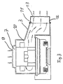
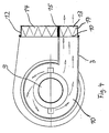
- Figures 1-4 are different sections through the shown upper part of a vacuum cleaner. This upper one Part is sealed on a not shown Dirt container attached.
- the dirt container, not shown contains an inflow opening for connecting the Vacuum cleaner suction tool.
- the working air flow is shown by arrows.
- the working air flow comes from the dirt container through the suction opening 2 in the housing 3 of the vacuum cleaner in the suction fan 1. Upstream of the passage opening 2 is a main filter device for the sucked-in, dirty air flow.
- the pre-filtered air flow is through the suction fan 1 and through the working air duct 4 to the outlet 5 of the Working air duct 4 out.
- the drive motor is a Electric motor with rotating rotor and fixed stator, with carbon brushes attached to the stator 8.
- a filter cassette 12 Downstream immediately in front of the outlet openings 10, 5 a filter cassette 12 is provided in the housing 3, which a filter area 13 for the cooling air and a filter area 14 for the working air.
- the filter areas 13, 14 are inside the filter cartridge 12 through an intermediate wall 15 fluidically separated from each other.
- the two filter areas 13, 14 are different Filter materials 16, 17 equipped.
- the filter material 16 in the working air area is around 1 - 2 filter classes according to DIN EN1822-1 higher than the filter material 17 in the cooling air area of the filter cassette.
Landscapes
- Engineering & Computer Science (AREA)
- Mechanical Engineering (AREA)
- Structures Of Non-Positive Displacement Pumps (AREA)
- Motor Or Generator Cooling System (AREA)
- Electric Suction Cleaners (AREA)
Applications Claiming Priority (2)
| Application Number | Priority Date | Filing Date | Title |
|---|---|---|---|
| DE29916719U | 1999-09-23 | ||
| DE29916719U DE29916719U1 (de) | 1999-09-23 | 1999-09-23 | Staubsauger |
Publications (2)
| Publication Number | Publication Date |
|---|---|
| EP1086647A1 true EP1086647A1 (fr) | 2001-03-28 |
| EP1086647B1 EP1086647B1 (fr) | 2004-03-31 |
Family
ID=8079293
Family Applications (1)
| Application Number | Title | Priority Date | Filing Date |
|---|---|---|---|
| EP20000120441 Expired - Lifetime EP1086647B1 (fr) | 1999-09-23 | 2000-09-19 | Aspirateur avec cassette de filtres |
Country Status (2)
| Country | Link |
|---|---|
| EP (1) | EP1086647B1 (fr) |
| DE (2) | DE29916719U1 (fr) |
Cited By (2)
| Publication number | Priority date | Publication date | Assignee | Title |
|---|---|---|---|---|
| DE20108544U1 (de) * | 2001-05-22 | 2002-10-02 | ALTO Deutschland GmbH, 89287 Bellenberg | Filterkassette für den Kühlluftstrom einer Turbine in einem Schmutzsauger |
| EP1444944A3 (fr) * | 2003-02-07 | 2005-06-29 | Stein & Co. GmbH | Filtre aspirateur pour les caissons des appareils pour le nettoyage de sols |
Citations (6)
| Publication number | Priority date | Publication date | Assignee | Title |
|---|---|---|---|---|
| JPH01107723A (ja) * | 1987-10-20 | 1989-04-25 | Mitsubishi Electric Corp | 電気掃除機 |
| US4934017A (en) * | 1985-07-17 | 1990-06-19 | Rug Doctor, Inc. | Modular vacuum cleaning system |
| JPH04330399A (ja) * | 1991-04-30 | 1992-11-18 | Sanyo Electric Co Ltd | 電気掃除機用電動送風機 |
| DE4315712A1 (de) * | 1993-05-11 | 1994-11-17 | Siemens Ag | Staubsauger |
| EP0826332A2 (fr) * | 1996-08-28 | 1998-03-04 | Aktiebolaget Electrolux | Dispositif pour un aspirateur |
| DE19925227A1 (de) * | 1998-06-03 | 1999-12-16 | Bsh Bosch Siemens Hausgeraete | Staubsauger |
-
1999
- 1999-09-23 DE DE29916719U patent/DE29916719U1/de not_active Expired - Lifetime
-
2000
- 2000-09-19 DE DE50005872T patent/DE50005872D1/de not_active Expired - Fee Related
- 2000-09-19 EP EP20000120441 patent/EP1086647B1/fr not_active Expired - Lifetime
Patent Citations (6)
| Publication number | Priority date | Publication date | Assignee | Title |
|---|---|---|---|---|
| US4934017A (en) * | 1985-07-17 | 1990-06-19 | Rug Doctor, Inc. | Modular vacuum cleaning system |
| JPH01107723A (ja) * | 1987-10-20 | 1989-04-25 | Mitsubishi Electric Corp | 電気掃除機 |
| JPH04330399A (ja) * | 1991-04-30 | 1992-11-18 | Sanyo Electric Co Ltd | 電気掃除機用電動送風機 |
| DE4315712A1 (de) * | 1993-05-11 | 1994-11-17 | Siemens Ag | Staubsauger |
| EP0826332A2 (fr) * | 1996-08-28 | 1998-03-04 | Aktiebolaget Electrolux | Dispositif pour un aspirateur |
| DE19925227A1 (de) * | 1998-06-03 | 1999-12-16 | Bsh Bosch Siemens Hausgeraete | Staubsauger |
Non-Patent Citations (2)
| Title |
|---|
| PATENT ABSTRACTS OF JAPAN vol. 017, no. 168 (M - 1391) 31 March 1993 (1993-03-31) * |
| PATENT ABSTRACTS OF JAPAN vol. 1999, no. 06 31 March 1999 (1999-03-31) * |
Cited By (2)
| Publication number | Priority date | Publication date | Assignee | Title |
|---|---|---|---|---|
| DE20108544U1 (de) * | 2001-05-22 | 2002-10-02 | ALTO Deutschland GmbH, 89287 Bellenberg | Filterkassette für den Kühlluftstrom einer Turbine in einem Schmutzsauger |
| EP1444944A3 (fr) * | 2003-02-07 | 2005-06-29 | Stein & Co. GmbH | Filtre aspirateur pour les caissons des appareils pour le nettoyage de sols |
Also Published As
| Publication number | Publication date |
|---|---|
| DE29916719U1 (de) | 2000-01-20 |
| DE50005872D1 (de) | 2004-05-06 |
| EP1086647B1 (fr) | 2004-03-31 |
Similar Documents
| Publication | Publication Date | Title |
|---|---|---|
| DE69507836T2 (de) | Filteranordnung für einen staubsauger | |
| DE69807752T2 (de) | Staubsauger | |
| DE60201019T2 (de) | Staubsauger | |
| DE102005015004B4 (de) | Mehrzyklon-Staubsammelvorrichtung und Staubsauger mit einer solchen | |
| DE60310033T2 (de) | Filtergehäuse | |
| DE102005008475B4 (de) | Zyklon-Staubsammelvorrichtung | |
| DE3404395C2 (fr) | ||
| DE10035253A1 (de) | Staubsauger | |
| DE69816933T2 (de) | Geräuscharmer Staubsauger | |
| DE2751735A1 (de) | Staubsauger | |
| DE4427739A1 (de) | Ansaugluftfilter | |
| DE2802369A1 (de) | Filtervorrichtung zum filtern von durch staub und faserabfaelle verunreinigter luft | |
| DE838741C (de) | Staubabscheider | |
| DE60006427T2 (de) | Trennvorrichtung für staubsauger | |
| DE102005020400A1 (de) | Einrichtung zum Filtern von extrem feinem Staub | |
| EP0184113A2 (fr) | Aspirateur de poussière | |
| DE3206714A1 (de) | Staubabsaugvorrichtung | |
| DE3341458C2 (de) | Staubsauger mit einem Abluftfilter | |
| DE661573C (de) | Staubsauger fuer Blas- und Saugluftbetrieb | |
| EP1086647B1 (fr) | Aspirateur avec cassette de filtres | |
| DE102019125002A1 (de) | Saugroboter und Verfahren zum Betrieb eines Saugroboters | |
| DE1482454B1 (de) | Umluftsichter | |
| EP3189760A1 (fr) | Machine de nettoyage du sol | |
| DE631580C (de) | Auf einem gemeinsamen Trag- oder Fahrgestell angeordneter Industriestaubsauger | |
| EP0392455A1 (fr) | Séparateur |
Legal Events
| Date | Code | Title | Description |
|---|---|---|---|
| PUAI | Public reference made under article 153(3) epc to a published international application that has entered the european phase |
Free format text: ORIGINAL CODE: 0009012 |
|
| AK | Designated contracting states |
Kind code of ref document: A1 Designated state(s): DE FR GB IT SE |
|
| AX | Request for extension of the european patent |
Free format text: AL;LT;LV;MK;RO;SI |
|
| 17P | Request for examination filed |
Effective date: 20010620 |
|
| AKX | Designation fees paid |
Free format text: DE FR GB IT SE |
|
| RAP1 | Party data changed (applicant data changed or rights of an application transferred) |
Owner name: ALFRED KAERCHER GMBH & CO. KG |
|
| GRAP | Despatch of communication of intention to grant a patent |
Free format text: ORIGINAL CODE: EPIDOSNIGR1 |
|
| GRAS | Grant fee paid |
Free format text: ORIGINAL CODE: EPIDOSNIGR3 |
|
| GRAA | (expected) grant |
Free format text: ORIGINAL CODE: 0009210 |
|
| AK | Designated contracting states |
Kind code of ref document: B1 Designated state(s): DE FR GB IT SE |
|
| REG | Reference to a national code |
Ref country code: GB Ref legal event code: FG4D Free format text: NOT ENGLISH |
|
| REF | Corresponds to: |
Ref document number: 50005872 Country of ref document: DE Date of ref document: 20040506 Kind code of ref document: P |
|
| GBT | Gb: translation of ep patent filed (gb section 77(6)(a)/1977) |
Effective date: 20040415 |
|
| PG25 | Lapsed in a contracting state [announced via postgrant information from national office to epo] |
Ref country code: SE Free format text: LAPSE BECAUSE OF FAILURE TO SUBMIT A TRANSLATION OF THE DESCRIPTION OR TO PAY THE FEE WITHIN THE PRESCRIBED TIME-LIMIT Effective date: 20040630 |
|
| ET | Fr: translation filed | ||
| PLBE | No opposition filed within time limit |
Free format text: ORIGINAL CODE: 0009261 |
|
| STAA | Information on the status of an ep patent application or granted ep patent |
Free format text: STATUS: NO OPPOSITION FILED WITHIN TIME LIMIT |
|
| 26N | No opposition filed |
Effective date: 20050104 |
|
| PGFP | Annual fee paid to national office [announced via postgrant information from national office to epo] |
Ref country code: FR Payment date: 20060801 Year of fee payment: 7 |
|
| PGFP | Annual fee paid to national office [announced via postgrant information from national office to epo] |
Ref country code: GB Payment date: 20060913 Year of fee payment: 7 |
|
| PGFP | Annual fee paid to national office [announced via postgrant information from national office to epo] |
Ref country code: IT Payment date: 20060930 Year of fee payment: 7 |
|
| PGFP | Annual fee paid to national office [announced via postgrant information from national office to epo] |
Ref country code: DE Payment date: 20061027 Year of fee payment: 7 |
|
| GBPC | Gb: european patent ceased through non-payment of renewal fee |
Effective date: 20070919 |
|
| PG25 | Lapsed in a contracting state [announced via postgrant information from national office to epo] |
Ref country code: DE Free format text: LAPSE BECAUSE OF NON-PAYMENT OF DUE FEES Effective date: 20080401 |
|
| REG | Reference to a national code |
Ref country code: FR Ref legal event code: ST Effective date: 20080531 |
|
| PG25 | Lapsed in a contracting state [announced via postgrant information from national office to epo] |
Ref country code: FR Free format text: LAPSE BECAUSE OF NON-PAYMENT OF DUE FEES Effective date: 20071001 |
|
| PG25 | Lapsed in a contracting state [announced via postgrant information from national office to epo] |
Ref country code: GB Free format text: LAPSE BECAUSE OF NON-PAYMENT OF DUE FEES Effective date: 20070919 |
|
| PG25 | Lapsed in a contracting state [announced via postgrant information from national office to epo] |
Ref country code: IT Free format text: LAPSE BECAUSE OF NON-PAYMENT OF DUE FEES Effective date: 20070919 |