EP1086730A2 - Appareil de représentation d'image et méthode et système de jeu de tir vidéo - Google Patents
Appareil de représentation d'image et méthode et système de jeu de tir vidéo Download PDFInfo
- Publication number
- EP1086730A2 EP1086730A2 EP00120776A EP00120776A EP1086730A2 EP 1086730 A2 EP1086730 A2 EP 1086730A2 EP 00120776 A EP00120776 A EP 00120776A EP 00120776 A EP00120776 A EP 00120776A EP 1086730 A2 EP1086730 A2 EP 1086730A2
- Authority
- EP
- European Patent Office
- Prior art keywords
- polygon
- display
- view
- displayed
- display sections
- Prior art date
- Legal status (The legal status is an assumption and is not a legal conclusion. Google has not performed a legal analysis and makes no representation as to the accuracy of the status listed.)
- Withdrawn
Links
- 238000000034 method Methods 0.000 title claims description 14
- 230000008859 change Effects 0.000 description 24
- 238000010586 diagram Methods 0.000 description 16
- 238000004364 calculation method Methods 0.000 description 11
- 238000010276 construction Methods 0.000 description 9
- 238000003384 imaging method Methods 0.000 description 9
- 238000001514 detection method Methods 0.000 description 5
- 230000035939 shock Effects 0.000 description 3
- 238000004088 simulation Methods 0.000 description 3
- 230000009466 transformation Effects 0.000 description 3
- 229920001971 elastomer Polymers 0.000 description 2
- 238000012986 modification Methods 0.000 description 2
- 230000004048 modification Effects 0.000 description 2
- 230000001902 propagating effect Effects 0.000 description 2
- 239000005060 rubber Substances 0.000 description 2
- 239000000872 buffer Substances 0.000 description 1
- 238000007599 discharging Methods 0.000 description 1
- 238000010304 firing Methods 0.000 description 1
- 230000012447 hatching Effects 0.000 description 1
- 239000004973 liquid crystal related substance Substances 0.000 description 1
- 230000003287 optical effect Effects 0.000 description 1
- 230000004044 response Effects 0.000 description 1
- 238000005070 sampling Methods 0.000 description 1
- 239000000779 smoke Substances 0.000 description 1
Images


Classifications
-
- A—HUMAN NECESSITIES
- A63—SPORTS; GAMES; AMUSEMENTS
- A63F—CARD, BOARD, OR ROULETTE GAMES; INDOOR GAMES USING SMALL MOVING PLAYING BODIES; VIDEO GAMES; GAMES NOT OTHERWISE PROVIDED FOR
- A63F13/00—Video games, i.e. games using an electronically generated display having two or more dimensions
- A63F13/80—Special adaptations for executing a specific game genre or game mode
- A63F13/837—Shooting of targets
-
- A63F13/10—
-
- A—HUMAN NECESSITIES
- A63—SPORTS; GAMES; AMUSEMENTS
- A63F—CARD, BOARD, OR ROULETTE GAMES; INDOOR GAMES USING SMALL MOVING PLAYING BODIES; VIDEO GAMES; GAMES NOT OTHERWISE PROVIDED FOR
- A63F13/00—Video games, i.e. games using an electronically generated display having two or more dimensions
- A63F13/40—Processing input control signals of video game devices, e.g. signals generated by the player or derived from the environment
- A63F13/42—Processing input control signals of video game devices, e.g. signals generated by the player or derived from the environment by mapping the input signals into game commands, e.g. mapping the displacement of a stylus on a touch screen to the steering angle of a virtual vehicle
- A63F13/426—Processing input control signals of video game devices, e.g. signals generated by the player or derived from the environment by mapping the input signals into game commands, e.g. mapping the displacement of a stylus on a touch screen to the steering angle of a virtual vehicle involving on-screen location information, e.g. screen coordinates of an area at which the player is aiming with a light gun
-
- A—HUMAN NECESSITIES
- A63—SPORTS; GAMES; AMUSEMENTS
- A63F—CARD, BOARD, OR ROULETTE GAMES; INDOOR GAMES USING SMALL MOVING PLAYING BODIES; VIDEO GAMES; GAMES NOT OTHERWISE PROVIDED FOR
- A63F13/00—Video games, i.e. games using an electronically generated display having two or more dimensions
- A63F13/45—Controlling the progress of the video game
-
- A—HUMAN NECESSITIES
- A63—SPORTS; GAMES; AMUSEMENTS
- A63F—CARD, BOARD, OR ROULETTE GAMES; INDOOR GAMES USING SMALL MOVING PLAYING BODIES; VIDEO GAMES; GAMES NOT OTHERWISE PROVIDED FOR
- A63F13/00—Video games, i.e. games using an electronically generated display having two or more dimensions
- A63F13/50—Controlling the output signals based on the game progress
- A63F13/52—Controlling the output signals based on the game progress involving aspects of the displayed game scene
-
- A—HUMAN NECESSITIES
- A63—SPORTS; GAMES; AMUSEMENTS
- A63F—CARD, BOARD, OR ROULETTE GAMES; INDOOR GAMES USING SMALL MOVING PLAYING BODIES; VIDEO GAMES; GAMES NOT OTHERWISE PROVIDED FOR
- A63F2300/00—Features of games using an electronically generated display having two or more dimensions, e.g. on a television screen, showing representations related to the game
- A63F2300/60—Methods for processing data by generating or executing the game program
- A63F2300/66—Methods for processing data by generating or executing the game program for rendering three dimensional images
-
- A—HUMAN NECESSITIES
- A63—SPORTS; GAMES; AMUSEMENTS
- A63F—CARD, BOARD, OR ROULETTE GAMES; INDOOR GAMES USING SMALL MOVING PLAYING BODIES; VIDEO GAMES; GAMES NOT OTHERWISE PROVIDED FOR
- A63F2300/00—Features of games using an electronically generated display having two or more dimensions, e.g. on a television screen, showing representations related to the game
- A63F2300/80—Features of games using an electronically generated display having two or more dimensions, e.g. on a television screen, showing representations related to the game specially adapted for executing a specific type of game
- A63F2300/8076—Shooting
Definitions
- the present invention relates to a technique for displaying images on a plurality of display devices at different angles of view and a technique of a shooting video game system for shooting an enemy character displayed on a display means by a simulated gun.
- a small-size auxiliary monitor is provided in a gunsight of the simulated gun in addition to the main monitor, and a part of a set game image in a range having a smaller angle of view than the main monitor is displayed on this auxiliary monitor so that a game player can easily see the enemy character.
- Image displaying devices for displaying images having different angles of view on two display units as in the conventional shooting video game systems are required to easily enable a realistic image display by making models such as characters appearing in the images seeable in more details when they are at a long distance from a viewing point than when they are at a short distance therefrom.
- an object of the present invention is to provide image displaying device and method, and a shooting video game system which can easily display realistic images when images having different angles of view are displayed on two display units.
- an image displaying device comprises: at least one display means provided with a first and a second display sections; display control means for displaying portions of an image of a model set in the virtual 3D space within ranges of different angles of view on the first and second display sections; polygon storage means for storing a plurality of polygon sets comprised of different numbers of polygons and representing the same model displayed on the first and second display sections; distance detecting means for detecting the distances from a viewing point to the model displayed on the first and second display sections in the virtual 3D space; correcting means for calculating a corrected value of the distance according to the angle of view of the image displayed on the first and second display sections from the viewing point; and polygon selecting means for selecting the polygon set used for displaying the model on the first and second display sections from the plurality of polygon sets based on the corrected value, wherein the display control means displays the model on the first and second display sections using the selected polygon set.
- FIG. 1 is a perspective view showing the external configuration of one embodiment of a shooting video game system according to the invention
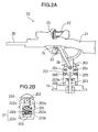
- FIGS. 2A and 2B show the construction of a simulated gun, wherein FIG. 2A is a side view partly in section of the simulated gun and FIG. 2B is a diagram showing an aiming direction detector.
- a video game system 1 is comprised of a main game unit 10 and a simulated gun 20.
- the main game unit 10 is provided with a main monitor 11 made of a CRT or PDP, a coin slot 12 through which a coin is inserted by a game player, and a start switch 13 operable by the game player.
- the main monitor 11 is arranged such that its center is substantially at the same level as a position slightly below the eyes of a standing person having an average height.
- the simulated gun 20 is opposed substantially to the center of the main monitor 11 and is installed on a base 14 of the main game unit 10 spaced apart from the main monitor 11 by a specified distance.
- the simulated gun 20 is, as shown in FIG. 2A, provided with a main gun unit 21, a cylindrical gunsight 22 disposed on the main gun unit 21, a trigger 23 disposed below the main gun unit 21 and a micro-switch 24.
- the main gun unit 21 is so mounted as to be vertically pivotal and horizontally rotatable.
- An auxiliary monitor 25 whose display surface is faced backward is arranged in the gunsight 22.
- the auxiliary monitor 25 is made of, for example, a liquid crystal display panel.
- the micro-switch 24 is provided in such a position that, when one end of the trigger 23 is pulled, the other end thereof is brought into contact with the micro-switch 24 to turn it on. When being turned on, the micro-switch 24 sends a trigger signal to a control unit 33 (see FIG. 6).
- the main gun unit 21 is mounted on a mount portion 201 fixed to the base 14. Specifically, the main gun unit 21 is made vertically pivotal about a horizontal shaft 202 by mounting the leading end of an extending member 26 extending from the main gun unit 21 on the horizontal shaft 202 and also made horizontally rotatable about a vertical shaft 203 by mounting the horizontal shaft 202 on the vertical shaft 203.
- a vertical pivotal range of the main gun unit 21 is restricted by stoppers 204 projecting from the mount portion 201. A shock created by this restriction is absorbed by shock absorbing rubbers 205 projecting from the mount portion 201.
- a horizontal rotatable range of the main gun unit 21 is restricted by shock absorbing rubbers (not shown).
- a small-diameter gear 202b is in mesh with a fan-shaped gear 202a mounted on the horizontal shaft 202, and a rotatable variable resistor 202c which functions as an angle of elevation sensor is mounted on a rotatable shaft of the gear 202b.
- the vertical shaft 203 is rotatably supported on a shaft bearing 15 of the base 14, and a rotatable variable resistor 203c which functions as a rotational angle sensor is mounted on a rotatable shaft of a small-diameter gear 203b in mesh with a gear 203a mounted on the vertical shaft 203.
- An aiming direction detector 27 is formed by the variable resistors 202c, 203c, which send detection signals of voltage levels corresponding to angles of rotation in the respective directions to the controller 23 (see FIG. 6), thereby making it possible to judge a direction at which a muzzle 28 is aimed at.
- the variable resistors encoders, potentiometers or like devices capable of detecting an angle may be used.
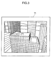
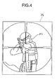
- FIGS. 3 and 4 show the same scene of the game, wherein FIG. 3 shows a display screen of the main monitor 11 and FIG. 4 shows a display screen of the auxiliary monitor 25.
- FIG. 5 is a diagram showing the display screen of the auxiliary monitor 25 in an other scene of the game.
- This shooting video game is such that the game player tries to shoot an enemy character P1 by means of the simulated gun (see FIG. 1) with models including buildings displayed as a background image on the main monitor 11 as shown in FIG. 3.
- FIG. 3 the scene in which the enemy character P1 hides himself on the roof of a high-rise building is displayed on the main monitor 11.
- a distance between a viewing point (for example, the position of the gunsight 22 of the simulated gun 20 in this embodiment) and the enemy character P1 i.e. a distance set in a virtual three-dimensional (3D) space (game space) in terms of calculation is long, and a range of the game image set in the virtual 3D space which range has a relatively wide angle of view is displayed. Accordingly, recognition can be only made as to whether the enemy character P1 is present or not.
- 3D three-dimensional
- FIG. 4 an enlarged image of a small area including an aimed position of the muzzle 28, i.e. a range of the game image set in the virtual 3D space which range has a narrow angle of view is displayed on the auxiliary monitor 25 as shown in FIG. 4.
- a display makes it possible to easily recognize a state where the enemy character P1 difficult to see on the main monitor 11 is aiming a gun at the game player.
- FIG. 4 a cross is displayed in a circular mark to make it understandable that the displayed screen is the screen of the auxiliary monitor 25 in the gunsight 22.
- FIGS. 3 and 4 show scenes where the enemy character P1 tries to counterattack the game player.
- FIG. 5 shows a scene immediately after the game player shot an enemy character P2.
- a simulated bullet D flying toward the enemy character P2 is displayed at the cross section in the center.
- FIG. 6 is a block diagram showing the electrical construction of the video game system and function blocks of the control unit 33. It should be noted that no description is given on the same elements as those shown in FIG. 1 by identifying them by the same reference numerals.
- This video game system is, as shown in FIG. 6, provided with the main monitor 11, the start switch 13, a coin detector 16, the micro-switch 24, the auxiliary monitor 25, the aiming direction detector 27, a ROM 31, a RAM 32 and the control unit 33.
- the coin detector 16 detects a coin inserted through the coin slot 12 (see FIG. 1) and sends a detection signal to the control unit 33.
- ROM 31 In the ROM 31 are stored a game program of this video game and various predetermined values set in advance as described later which are part of the game program.
- polygon data constructing fixed models such as still enemy characters and building characters, movable models moving on the ground such as car characters, flying models flying in the air such as helicopter characters and airplane characters, and simulated bullets which look as if they were fired from the simulated gun 20 are also stored in the ROM 31 as part of the game program of the video game.
- Texture data used to image the respective models are also stored in the ROM 31 as part of the game program of the video game.
- Models are usually formed by a polygon set comprised of a plurality of polygons and imaged by adhering textures to the respective polygons.
- first, second and third polygon sets comprised of different numbers of polygons are stored in the ROM 31 as polygon sets for forming the same model (polygon storage means).
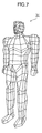
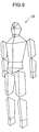
- FIGS. 7 to 9 are polygon mesh representations showing polygon sets forming models representing the same human character (e.g. an enemy character).
- FIG. 7 shows the first polygon set 34 comprised of a largest number (e.g. about 1000 in this embodiment) of polygons
- FIG. 8 shows the second polygon set 35 comprised of a smaller number (e.g. about 500 in this embodiment) of polygons
- FIG. 9 shows the third polygon set 36 comprised of an even smaller number (e.g. about 100 in this embodiment) of polygons.
- the first polygon set 34 of FIG. 7 is used if the distance from the viewing point to the enemy character is a short distance;
- the second polygon set 35 of FIG. 8 is used if the distance from the viewing point to the enemy character is a medium distance;
- the third polygon set 36 of FIG. 9 is used if the distance from the viewing point to the enemy character is a long distance.
- the texture data corresponding to the first to third polygon sets 34 to 36 are stored in the ROM 31.
- FIGS. 10 and 11 are diagrams showing models of enemy characters displayed on the auxiliary monitor 25 in different display modes.
- FIG. 10 shows a state where an enemy character P3 is displayed on the auxiliary monitor 25 in a thermographical display mode expressing a scanned image of a human, which would be obtained by a thermograph, in a simulated manner.
- FIG. 11 shows a state where an enemy character P4 is displayed on the auxiliary monitor 25 in a simulated skeleton display mode expressing a skeleton image of a human, which would be obtained by an X-ray testing apparatus, in a simulated manner. Displays in these different display modes are described later.
- the RAM 32 has a non-display area and two display areas (frame buffers). Data read from the ROM 31 and various calculation results are temporarily stored in the non-display area, whereas image data to be displayed on the respective monitors 11, 25 are written in the two display areas.
- the control unit 33 is comprised of one or more CPUs and an input/output circuit, conducts various calculations in a specified sampling cycle, and displays images on the main monitor 11 and the auxiliary monitor 25 using the calculation results.
- the control unit 33 is provided with a game control unit 41, a signal processing unit 42, and an imaging unit 43 as function blocks.
- the game control unit 41 proceeds the game by generating commands as tasks for imaging in accordance with the game program stored in the ROM 31, ON/OFF signals sent from the micro-switch 24 of the simulated gun 20 and the detection signals sent from the aiming direction detector 27.
- the game control unit 41 has a function as a coin discriminating means for discriminating whether a coin has been inserted through the coin slot 12 (see FIG. 1) based on whether it has received a detection signal from the coin detector 16, and a function as a start discriminating means for discriminating whether the start switch 13 has been pressed by the game player based on whether it has received a switch signal from the start switch 13.
- the signal processing unit 42 conducts calculation of positions of characters and models in the virtual 3D space, calculation for the perspective projection transformation from the position in the virtual 3D space into a position on the plane of the monitor, and a light source calculation. For example, when the simulated bullet fired from the simulated gun 20 is displayed, the signal processing unit 42 conducts a calculation to move a polygon set forming the simulated bullet in accordance with a trajectory simulation set in advance.
- the imaging unit 43 forms images on the main monitor 11 and the auxiliary monitor 25 by writing the image data to be formed in the RAM 32 and writing the texture data in the areas of the RAM 32 designated by the polygons in accordance with the calculation results in the signal processing unit 42.
- Polygon data defining models, texture data, etc. are stored in correspondence in the RAM 32.
- Polygons are polygonal two-dimensional (2D) virtual figures for forming an object, i.e. a model set in the virtual 3D space (game space).
- polygons are triangle.
- Texture data are 2D image data to be adhered to the polygons to form an image.
- Imaging commands generated by the game control unit 41 include commands for forming a 3D image using the polygons.
- Each command for forming a 3D image using the polygons is comprised of polygon apex address data in the display area of the RAM 32, texture address data representing the stored position of the texture data to be adhered to the polygons in the RAM 32, and luminance data representing the luminance of the textures.
- the polygon apex address data in the display area are polygon apex coordinate data in a 2D space obtained by the signal processing unit 42 applying a coordinate transformation and a perspective projection transformation to the polygon apex coordinate data in the 3D space from the game control unit 41 based on a moved amount data and a rotated amount data of the screen itself (viewing point).
- the polygon apex address data represent addresses in the display areas of the RAM 32.
- the imaging unit 43 writes the texture data represented by the texture address data allotted in advance in a range of the display area of the RAM 32 represented by three polygon apex address data.
- objects (models) formed by adhering the texture data to a multitude of polygons are displayed on the display surfaces of the main monitor 11 and the auxiliary monitor 25.
- the game control unit 41 is further provided with a position calculating means 51, a bullet control means 52, a hit judging means 53, an angle of view detecting means 54, a distance detecting means 55, a correcting means 56, a polygon selecting means 57, a change instructing means 58 and a display control means 59 as function blocks.
- the display control means 59 has a function of generating the imaging commands and is provided with a main display control device 61 for generating commands for the main monitor 11, an auxiliary display control device 62 for generating commands for the auxiliary monitor 25, and a change display control device 63 to be described later.
- the position calculating means 51 has a function of calculating the position of an intersection of the trajectory of the simulated bullet with the screen of the main monitor 11 when the simulated bullet is fired from the muzzle 28 of the simulated gun 20 in accordance with the detection signal from the aiming direction detector 27. This intersection calculation is carried out frame by frame (e.g. 1/60 sec. in this embodiment) regardless of whether or not the simulated bullet has been fired.
- the bullet control means 52 has functions of generating a bullet firing signal every time the trigger 25 is pulled, and, every time this signal is generated, reading the apex coordinate data of the polygons forming the simulated bullet and other data from the ROM 31 and carrying out the trajectory simulation for calculating the trajectory of the simulated bullet fired from the simulated gun 20 frame by frame in accordance with the position of the intersection calculated by the position calculating means 51, the propagating direction of the simulated bullet on the main monitor 11 which is so set in advance as to correspond to the position of the intersection (direction data corresponding to the positions of the intersection are stored in a table format in the ROM 31 in this embodiment) and a speed (e.g. Mach 3) of the simulated bullet set in advance.
- a speed e.g. Mach 3
- the trajectory simulation is carried out frame by frame for each simulated bullet.
- the propagating direction of the simulated bullet on the main monitor 11 is set at a depth direction of the game image displayed on the main monitor 11 along a line connecting the position of the intersection and the position of the simulated gun 20.
- the hit judging means 53 has a function of judging whether each simulated bullet has hit the model by judging whether the trajectory of each simulated bullet intersects with the model displayed on the main monitor 11. The judgment is made by judging by calculation whether a hit judging surface set for each displayed model and the trajectory data of the simulated bullet intersect in the 3D coordinate systems.
- the angle of view detecting means 54 has a function of detecting angles of view of the game images displayed on the main monitor 11 and the auxiliary monitor 25.
- the distance detecting means 55 has a function of detecting distances from the viewing point to the respective models displayed on the main monitor 11 and the auxiliary monitor 25.
- the main display control means 61 and the auxiliary display control means 62 send commands to display images within ranges of preset angles of view from a preset viewing point in the game space set in the virtual 3D space as game images on the main monitor 11 and the auxiliary monitor 25 to the signal processing unit 42 and the imaging unit 43 in accordance with the game program stored in the ROM 31, respectively.
- the angle of view detecting means 54 detects the angles of view on the respective monitors 11, 25 frame by frame
- the distance detecting means 55 detects the distances from the viewing point to the respective models on the respective monitors 11, 25 frame by frame.
- the polygon selecting means 57 has a function of selecting a polygon set used to display the model on the main monitor 11 and the auxiliary monitor 25 from the first to third polygon sets 34 to 36 (see FIGS. 7 to 9) in accordance with the corrected value L. This selection is made by comparing the corrected value with predetermined values L1, L2 (> L1): the first polygon set 34 is selected when L ⁇ L1, the second polygon set 35 is selected when L1 ⁇ L ⁇ L2, and the third polygon set 36 is selected when L2 ⁇ L.
- FIG. 12 is a diagram used to explain selection of the polygon set.
- the first polygon set 34 is selected when H ⁇ 10(m); the second polygon set 35 is selected when 10(m) ⁇ H ⁇ 20(m); and the third polygon set 36 is selected when 20(m) ⁇ H.
- the first polygon set 34 is selected when H ⁇ 65.99(m); the second polygon set 35 is selected when 65.99(m) ⁇ H ⁇ 131.98(m); and the third polygon set 36 is selected when 131.98(m) ⁇ H in accordance with equation (1) as shown in FIG. 12.
- the polygon sets used to display the model are selected based on the corrected value L of the distance H calculated according to the angle of view ⁇ in accordance with equation (1).
- suitable polygon sets corresponding to the distance can be easily selected for both monitors 11 and 25.
- suitable images can be realistically displayed on the monitors 11 and 25.
- the change instructing means 58 has a function of instructing a change of the display mode of the enemy character on the auxiliary monitor 25 to the different display modes described above.
- this video game is comprised of a plurality of game stages, in each of which the display mode of the enemy character on the auxiliary monitor 25 is set beforehand at a usual mode as shown in FIG. 4 or at a see-through mode as shown in FIG. 10 or 11.
- the above instruction is given by the change instructing means 58.
- an operable member 72 including, for example, an operation switch provided on the simulated gun 20 and adapted to send an operation signal to the control unit 33 upon being operated.
- the change instructing means 58 may give the above instruction in accordance with the operation signal from the operable member 72.
- the main display control device 61 may have a function of generating a command to display a specified character on the main monitor 11, and the change instructing means 58 may give an instruction to change the display mode of the enemy character on the auxiliary monitor 25 to a different display mode when the hit judging means 53 judges that the simulated bullet fired from the simulated gun 20 (see FIG. 1) hit the specified character.
- the game player can change the display mode of the enemy character to a different one in a desired game scene, which makes the game more interesting.
- the main display control device 61 of the display control means 59 has a function of generating a command to display a portion of the game image set in the virtual 3D space within a range of a specified angle of view from a specified viewing point on the main monitor 11 depending on the progress of the game.
- the auxiliary display control device 62 has a function of generating a command to display a portion of the game image displayed on the main monitor 11 which portion includes a part aimed at by the simulated gun 20 and is located within a range of a specified angle of view smaller than the one used in the main display control device 61.
- the main and auxiliary display control devices 61, 62 generate various other commands for the display, including a command to display the simulated bullet generated by the bullet control means 52 and a command for the screen display showing a success of shooting in response to the hit judgment made by the hit judging means 53 by, for example, causing the model hit by the simulated bullet, e.g. the enemy character to fall backward or disappear from the game screen.
- the change display control device 63 has a function of generating a command to display the enemy character on the auxiliary monitor 25 in the aforementioned different display mode as shown in FIG. 10 or 11 upon the instruction by the change instructing means 58.
- FIGS. 13 and 14 are diagrams showing examples of the display scenes on the main monitor 11 when the instruction is given from the change instructing means 58.
- FIG. 13 shows a state where enemy characters (indicated by "TARGET” in FIG. 13) cannot be seen with sight being blocked by obstacles 71. Even in this state, if the instruction is given from the change instruction means 58, the change display control means 63, for example, causes the enemy character P3 to be displayed as a simulated thermographical image on the auxiliary monitor 25 as shown in FIG. 10, so that the enemy character P3 can be easily visually recognizable.
- the change display control means 63 causes the enemy character P3 to be displayed as a simulated thermographical image on the auxiliary monitor 25 as shown in FIG. 10, so that the enemy character P3 can be easily visually recognizable.
- FIG. 14 shows a state where enemy characters (indicated by "TARGET” in FIG. 14) are difficult to see with sight being blocked by the darkness or smoke (indicated by hatching in FIG. 14). Even in this state, if the instruction is given from the change instruction means 58, the change display control means 63, for example, causes the enemy character P4 to be displayed as a simulated skeleton image on the auxiliary monitor 25 as shown in FIG. 11, so that the enemy character P4 can be easily visually recognizable.
- the change display control means 63 causes the enemy character P4 to be displayed as a simulated skeleton image on the auxiliary monitor 25 as shown in FIG. 11, so that the enemy character P4 can be easily visually recognizable.
- the change display control means 63 causes the enemy character to be displayed in the different display mode on the auxiliary monitor 25 when the instruction is given from the change instructing means 58. Accordingly, the enemy character can be easily visually recognizable. This enables the game player to shoot the enemy character in such a case, making the shooting video game more interesting and exciting. Further, unlike the simple shooting video game for shooting enemy characters, a variety of images including darkness and obstacles can be displayed on the main monitor 11, thereby making the game more enjoyable.
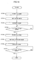
- Step ST100 an angle of view of an image being displayed is detected (Step ST100), a distance from a viewing point to a displayed model is detected (Step ST110) and a corrected value of the distance corresponding to the angle of view is calculated by equation (1) (Step ST120).
- a polygon set used for the displayed model is selected based on the corrected value (Step ST130), and an imaging command for the displayed model is generated using the selected polygon set (Step ST140).
- This operation procedure is carried out frame by frame for both the main monitor 11 and the auxiliary monitor 25, and Steps ST110 to ST140 are performed for all models displayed on the respective monitors 11, 25.
- Step ST200 When the video game system is turned on, a first game stage is started (Step ST200) after a specified procedure including the display of a demonstration screen and an initialization screen is carried out (not shown).
- the usual mode is first set (Step ST210). Thus, no instruction is given from the change instructing means 58 in the first game stage. Subsequently, the game in the first game stage is performed (Step ST220) until the end of the first game stage (NO in Step ST230), proceeding to the next stage.
- Step ST240 Upon the end of the first game stage (YES in Step St230), a second game stage is started next (Step ST240). First, an instruction is given from the change instructing means 58 to set the see-through mode (Step ST250). Accordingly, in the second stage, when an image as shown in FIG. 13 or 14 is displayed in the second game stage, the enemy character is displayed in a different display mode on the auxiliary monitor 25 as shown in FIG. 10 or 11.
- Step ST260 The game of the second game stage is continued (Step ST260) until the end of the second game stage (NO in Step ST270).
- Step ST270 Upon the end of the second game stage (YES in Step ST270), a third game stage or the like is started (not shown).
- the present invention is not limited to the foregoing embodiment, and may be embodied as follows.
- the inventive image displaying device is provided with the first and second display sections which are formed by at least one display means, the display control means for displaying portions of an image of a model set in the virtual 3D space within ranges of different angles of view on the first and second display sections, the polygon storage means for storing a plurality of polygon sets comprised of different numbers of polygons and representing the same models displayed on the first and second display sections, the distance detecting means for detecting the distances from the viewing point to the models displayed on the first and second display sections in the virtual 3D space, the correcting means for calculating the corrected values of the distances according to the angles of view of the images displayed on the first and second display sections from the viewing point, and the polygon selecting means for selecting the polygon sets used for displaying the model on the first and second display sections from the plurality of polygon sets based on the corrected values, wherein the display control means displays the models on the first and second display sections using the selected polygon sets.
- a plurality of polygon sets comprised of different numbers of polygons and representing the same models displayed on the first and second display sections which are formed by at least one display means are stored.
- the model set in the virtual 3D space is displayed on the first and second display sections
- the distances from the viewing point in the virtual 3D space to the models displayed on the first and second display sections are respectively detected.
- the corrected values of the detected distances according to the angles of view of the images displayed on the first and second display sections from the viewing point are calculated.
- the polygon sets used for displaying the models on the first and second display sections are selected from the plurality of polygon sets based on the corrected values, and the models are displayed on the first and second display sections using the selected polygon sets.
- suitable polygon sets corresponding to the distances and taking the angles of view into consideration are used for the display section for displaying an image having a relatively large angle of view and for the display section for displaying an image having a smaller angle of view, i.e. an enlarged image.
- the models can be suitably displayed.
- the polygon storage means may store the first polygon set comprised of a plurality of polygons and representing the model displayed on the first and second display sections, and the second polygon set comprised of a smaller number of polygons than the first polygon set and representing the same model as the first polygon set; the correcting means may correct the distance according to a ratio of an actual angle of view to the standard angle of view set in advance; and the polygon selecting means may select the first polygon set when the corrected value is smaller than a predetermined value while selecting the second polygon set when it is equal to or larger than the predetermined value.
- the first polygon set comprised of a plurality of polygons and representing the model displayed on the first and second display sections
- the second polygon set comprised of a smaller number of polygons than the first polygon set and representing the same model as the first polygon set are stored.
- the second polygon set having a smaller number of polygons is used.
- the models can be suitably displayed by using the suitable polygon sets according to the distances calculated taking the angles of view into consideration for both the first and second display sections.
- the polygon storage means may additionally store the third polygon set comprised of a smaller number of polygons than the second polygon set and representing the same model as the first polygon set are stored, and the polygon selecting means may select the third polygon set when the corrected value is equal to or larger than a second predetermined value which is larger than the above predetermined value.
- the third polygon set having an even smaller number of polygons is used.
- suitable polygon sets taking the angles of view into consideration and corresponding to the distances are used for the first and second display sections.
- the models can be suitably displayed.
- the first and second display sections may be formed by one display means, and the display control means may display, as the first display section, the image at a first angle of view in a small area on the display means and display, as the second display section, the image at a second angle of view larger than the first angle of view in a remaining area on the display means excluding the small area.
- suitable polygon sets taking the angles of view into consideration and corresponding to the distances are used for both the first display section for displaying the image in the small area on the one display means at the first angle of view and the second display section for displaying the image in the remaining area on the display means excluding the small area at the second angle of view larger than the first angle of view.
- the models can be suitably displayed.
- first and second display sections are formed by two different display means, suitable polygon sets taking the angles of view into consideration and corresponding to the distances are used for both display sections.
- the models can be suitably displayed.
- the inventive image displaying method for displaying a model set in the virtual 3D space at different angles of view on the first and second display sections which are formed by at least one display means comprises the steps of storing a plurality of polygon sets comprised of different numbers of polygons and representing the same models to be displayed on the first and second display sections; detecting the distances from the viewing point in the virtual 3D space to the models displayed on the first and second display sections; calculating the corrected values of the distances according to the angles of view of the images displayed on the first and second display sections from the viewing point; selecting the polygon sets used for displaying the models on the first and second display sections from the plurality of polygon sets based on the corrected values; and displaying the models on the first and second display sections using the selected polygon sets.
- a plurality of polygon sets comprised of different numbers of polygons and representing the same models displayed on the first and second display sections which are formed by at least one display means are stored.
- the distances from the viewing point in the virtual 3D space to the models displayed on the first and second display sections are respectively detected.
- the corrected values of the detected distances according to the angles of view of the images displayed on the first and second display sections from the viewing point are calculated.
- the polygon sets used for displaying the models on the first and second display sections are selected from the plurality of polygon sets based on the corrected values, and the models are displayed on the first and second display sections using the selected polygon sets.
- suitable polygon sets corresponding to the distances and taking the angles of view into consideration are used for the display section for displaying an image having a relatively large angle of view and for the display section for displaying an image having a smaller angle of view, i.e. an enlarged image.
- the models can be suitably displayed.
- the inventive shooting video game system for shooting enemy characters displayed on the main monitor by the simulated gun from a position facing the main monitor is provided with the main display control means for displaying a portion of a game image set in the virtual 3D space and comprised of models including enemy characters within a range of a specified angle of view on the main monitor; the auxiliary monitor provided in the gunsight of the simulated gun, the auxiliary display control means for displaying a portion of the game image including a part at which the simulated gun is aimed within a range of an angle of view smaller than the specified angle of view on the auxiliary monitor; the polygon storage means for storing a plurality of polygon sets comprised of different numbers of polygons and representing the same models to be displayed on the main and auxiliary monitors, the distance detecting means for detecting the distances from the viewing point in the virtual 3D space to the models displayed on the main and auxiliary monitors, the correcting means for calculating the corrected values of the distances according to the angles of view of the images displayed on the main and auxiliary monitors from
- a plurality of polygon sets comprised of different numbers of polygons and representing the same models to be displayed on the main and auxiliary monitors are stored; the portion of the game image set in the virtual 3D space and comprised of the models including the enemy character within the range of the specified angle of view is displayed on the main monitor, whereas the portion of the game image displayed on the main monitor including the part at which the simulated gun is aimed within the range of the angle of view smaller than the specified angle of view is displayed on the auxiliary monitor.
- the distances from the viewing point in the virtual 3D space to the models displayed on the main and auxiliary monitors are respectively detected.
- the corrected values of the detected distances according to the angles of view of the images displayed on the main and auxiliary monitors from the viewing point are calculated.
- the polygon sets used for displaying the models on the main and auxiliary monitors are selected from the plurality of polygon sets based on the corrected values, and the models are displayed on the main and auxiliary monitors using the selected polygon sets. Accordingly, suitable polygon sets corresponding to the distances are used for the main monitor for displaying an image having a relatively large angle of view and for the auxiliary monitor for displaying an image having a smaller angle of view, i.e. an enlarged image. As a result, the models can be suitably displayed.
Landscapes
- Engineering & Computer Science (AREA)
- Multimedia (AREA)
- Human Computer Interaction (AREA)
- Processing Or Creating Images (AREA)
- Image Generation (AREA)
Applications Claiming Priority (2)
| Application Number | Priority Date | Filing Date | Title |
|---|---|---|---|
| JP27052499 | 1999-09-24 | ||
| JP27052499A JP2001087544A (ja) | 1999-09-24 | 1999-09-24 | 画像表示装置、画像表示方法および射的ビデオゲーム装置 |
Publications (2)
| Publication Number | Publication Date |
|---|---|
| EP1086730A2 true EP1086730A2 (fr) | 2001-03-28 |
| EP1086730A3 EP1086730A3 (fr) | 2002-10-30 |
Family
ID=17487433
Family Applications (1)
| Application Number | Title | Priority Date | Filing Date |
|---|---|---|---|
| EP00120776A Withdrawn EP1086730A3 (fr) | 1999-09-24 | 2000-09-22 | Appareil de représentation d'image et méthode et système de jeu de tir vidéo |
Country Status (5)
| Country | Link |
|---|---|
| EP (1) | EP1086730A3 (fr) |
| JP (1) | JP2001087544A (fr) |
| KR (1) | KR20010050620A (fr) |
| CN (1) | CN1146460C (fr) |
| TW (1) | TW458796B (fr) |
Cited By (3)
| Publication number | Priority date | Publication date | Assignee | Title |
|---|---|---|---|---|
| US6980690B1 (en) | 2000-01-20 | 2005-12-27 | Canon Kabushiki Kaisha | Image processing apparatus |
| CN105825539A (zh) * | 2016-03-16 | 2016-08-03 | 成都电锯互动科技有限公司 | 一种三维动画制作方法 |
| CN116343399A (zh) * | 2022-03-25 | 2023-06-27 | 株式会社万代 | 物品供给装置 |
Families Citing this family (6)
| Publication number | Priority date | Publication date | Assignee | Title |
|---|---|---|---|---|
| JP4187768B2 (ja) | 2007-03-20 | 2008-11-26 | 株式会社コナミデジタルエンタテインメント | ゲーム装置、進行制御方法、および、プログラム |
| JP4951696B2 (ja) * | 2010-07-15 | 2012-06-13 | 株式会社コナミデジタルエンタテインメント | ゲームシステム、その制御方法及び、コンピュータプログラム |
| JP4951697B2 (ja) * | 2010-07-15 | 2012-06-13 | 株式会社コナミデジタルエンタテインメント | ゲームシステム、その制御方法及び、コンピュータプログラム |
| CN104537708B (zh) * | 2014-12-12 | 2017-05-17 | 北京师范大学 | 一种基于测地线的躺卧三维颅面模型的直立矫正方法 |
| US20170097827A1 (en) * | 2015-10-06 | 2017-04-06 | Microsoft Technology Licensing, Llc | Role-specific device behavior |
| CN114377397B (zh) * | 2022-01-21 | 2025-07-25 | 腾讯科技(深圳)有限公司 | 虚拟场景中的寻路方法、装置、设备及存储介质 |
Family Cites Families (4)
| Publication number | Priority date | Publication date | Assignee | Title |
|---|---|---|---|---|
| JPH07181934A (ja) * | 1993-12-22 | 1995-07-21 | Sega Enterp Ltd | 画像表示装置 |
| US5764232A (en) * | 1994-09-16 | 1998-06-09 | Namco Ltd. | Three-dimensional simulator apparatus and image synthesis method |
| JPH10328418A (ja) * | 1997-05-29 | 1998-12-15 | Calsonic Corp | レーシングゲームの画像データおよび画像処理プログラムが記録された記録媒体ならびにレーシングゲーム装置 |
| JP3183632B2 (ja) * | 1997-06-13 | 2001-07-09 | 株式会社ナムコ | 情報記憶媒体及び画像生成装置 |
-
1999
- 1999-09-24 JP JP27052499A patent/JP2001087544A/ja active Pending
-
2000
- 2000-09-22 TW TW089119681A patent/TW458796B/zh not_active IP Right Cessation
- 2000-09-22 EP EP00120776A patent/EP1086730A3/fr not_active Withdrawn
- 2000-09-23 KR KR1020000056020A patent/KR20010050620A/ko not_active Ceased
- 2000-09-25 CN CNB001249266A patent/CN1146460C/zh not_active Expired - Fee Related
Non-Patent Citations (1)
| Title |
|---|
| FUNKHOUSER, SEQUIN, TELLER: "Management of Large Amount of Data in Interactive Building Walkthrough", PROC. SYMP. ON INTERACTIVE 3D GRAPHICS, 1992 * |
Cited By (4)
| Publication number | Priority date | Publication date | Assignee | Title |
|---|---|---|---|---|
| US6980690B1 (en) | 2000-01-20 | 2005-12-27 | Canon Kabushiki Kaisha | Image processing apparatus |
| US7508977B2 (en) | 2000-01-20 | 2009-03-24 | Canon Kabushiki Kaisha | Image processing apparatus |
| CN105825539A (zh) * | 2016-03-16 | 2016-08-03 | 成都电锯互动科技有限公司 | 一种三维动画制作方法 |
| CN116343399A (zh) * | 2022-03-25 | 2023-06-27 | 株式会社万代 | 物品供给装置 |
Also Published As
| Publication number | Publication date |
|---|---|
| EP1086730A3 (fr) | 2002-10-30 |
| CN1302676A (zh) | 2001-07-11 |
| JP2001087544A (ja) | 2001-04-03 |
| CN1146460C (zh) | 2004-04-21 |
| KR20010050620A (ko) | 2001-06-15 |
| TW458796B (en) | 2001-10-11 |
Similar Documents
| Publication | Publication Date | Title |
|---|---|---|
| US6582299B1 (en) | Target shooting video game device, and method of displaying result of target shooting video game | |
| US7140962B2 (en) | Video game apparatus, image processing method and program | |
| KR100276549B1 (ko) | 화상생성장치,화상생성방법및이것을이용한게임기 | |
| US6672962B1 (en) | Gun-shaped controller and game device | |
| US8142277B2 (en) | Program, game system, and movement control method for assisting a user to position a game object | |
| EP0952555B1 (fr) | Machine de jeu et support d'enregistrement | |
| EP1086729A2 (fr) | Système de jeu de tir vidéo et méthode de représentation d'image dans un jeu de tir vidéo | |
| US10046233B2 (en) | Game machine controller | |
| US6634947B1 (en) | Video game system and video game memory medium | |
| EP1585063B1 (fr) | Dispositif de génération d'images, méthode de affichage d'images et produit de logiciel. | |
| US20100066736A1 (en) | Method, information storage medium, and game device | |
| EP2368612A2 (fr) | Système de génération d'images et procédé de contrôle du système de génération d'images | |
| JPH078632A (ja) | 3次元ゲーム装置 | |
| EP1086730A2 (fr) | Appareil de représentation d'image et méthode et système de jeu de tir vidéo | |
| JP4054037B2 (ja) | シューティング型ゲーム機 | |
| EP1170042B1 (fr) | Appareil de jeu video de tir sur cible et procede d'affichage de resultat de jeu video de tir sur cible | |
| JPH10244073A (ja) | 射撃ビデオゲーム装置 | |
| TW487591B (en) | Dart video game device and shooting result display method of dart video game | |
| JP2002331165A (ja) | ゲーム機におけるマーカーの色変更装置及び情報記録媒体 | |
| HK1081307B (en) | Image generation device, image display method and program product |
Legal Events
| Date | Code | Title | Description |
|---|---|---|---|
| PUAI | Public reference made under article 153(3) epc to a published international application that has entered the european phase |
Free format text: ORIGINAL CODE: 0009012 |
|
| AK | Designated contracting states |
Kind code of ref document: A2 Designated state(s): AT BE CH CY DE DK ES FI FR GB GR IE IT LI LU MC NL PT SE |
|
| AX | Request for extension of the european patent |
Free format text: AL;LT;LV;MK;RO;SI |
|
| PUAL | Search report despatched |
Free format text: ORIGINAL CODE: 0009013 |
|
| AK | Designated contracting states |
Kind code of ref document: A3 Designated state(s): AT BE CH CY DE DK ES FI FR GB GR IE IT LI LU MC NL PT SE |
|
| AX | Request for extension of the european patent |
Free format text: AL;LT;LV;MK;RO;SI |
|
| RIC1 | Information provided on ipc code assigned before grant |
Free format text: 7A 63F 13/10 A, 7A 63F 13/08 B |
|
| 17P | Request for examination filed |
Effective date: 20030306 |
|
| AKX | Designation fees paid |
Designated state(s): GB |
|
| REG | Reference to a national code |
Ref country code: DE Ref legal event code: 8566 |
|
| 17Q | First examination report despatched |
Effective date: 20041015 |
|
| 17Q | First examination report despatched |
Effective date: 20041015 |
|
| STAA | Information on the status of an ep patent application or granted ep patent |
Free format text: STATUS: THE APPLICATION IS DEEMED TO BE WITHDRAWN |
|
| 18D | Application deemed to be withdrawn |
Effective date: 20070424 |