EP1086770A2 - Säge mit einklappbarem Sägeblatt - Google Patents
Säge mit einklappbarem Sägeblatt Download PDFInfo
- Publication number
- EP1086770A2 EP1086770A2 EP00116323A EP00116323A EP1086770A2 EP 1086770 A2 EP1086770 A2 EP 1086770A2 EP 00116323 A EP00116323 A EP 00116323A EP 00116323 A EP00116323 A EP 00116323A EP 1086770 A2 EP1086770 A2 EP 1086770A2
- Authority
- EP
- European Patent Office
- Prior art keywords
- blade
- handle
- protective cover
- housing groove
- edge
- Prior art date
- Legal status (The legal status is an assumption and is not a legal conclusion. Google has not performed a legal analysis and makes no representation as to the accuracy of the status listed.)
- Granted
Links
Images






Classifications
-
- B—PERFORMING OPERATIONS; TRANSPORTING
- B23—MACHINE TOOLS; METAL-WORKING NOT OTHERWISE PROVIDED FOR
- B23D—PLANING; SLOTTING; SHEARING; BROACHING; SAWING; FILING; SCRAPING; LIKE OPERATIONS FOR WORKING METAL BY REMOVING MATERIAL, NOT OTHERWISE PROVIDED FOR
- B23D51/00—Sawing machines or sawing devices working with straight blades, characterised only by constructional features of particular parts; Carrying or attaching means for tools, covered by this subclass, which are connected to a carrier at both ends
- B23D51/02—Sawing machines or sawing devices working with straight blades, characterised only by constructional features of particular parts; Carrying or attaching means for tools, covered by this subclass, which are connected to a carrier at both ends of beds; of guiding arrangements for work-tables or saw carriers; of frames
- B23D51/03—Sawing machines or sawing devices working with straight blades, characterised only by constructional features of particular parts; Carrying or attaching means for tools, covered by this subclass, which are connected to a carrier at both ends of beds; of guiding arrangements for work-tables or saw carriers; of frames with extensible or collapsible frames ; Frames with spare blade storage means
Definitions
- Saws in which the blade is pivotally attached at its base end to the top end of a handle having a U-shaped cross section, so that the blade can be folded into the handle when not in use, are known. They are used as a pruning saw, a gardening saw or as a crafting saw.
- the present invention relates to such a hand saw where the blade can be folded into a handle (hereinafter referred to as a "folding saw").
- a conventional folding saw has a straight blade pivotally attached by its base end to the top end of a straight handle. When the blade is folded into the handle, the edge is completely housed within the handle.
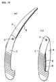
- saws having a concavely curved blade A and a concavely curved edge B as shown in FIG. 15 (a) have come into widespread use for pruning trees.
- Such saws having a concavely curved blade edge are generally called curved saws.
- a curved saw is less likely to disengage from the object of cutting, so it is easier to cut the object using such a saw.
- FIG. 15 having a concavely curved edge B housed in a handle C which is also concave in the same direction as the edge B has been developed.
- Other variations of the folding saw include those having a concave edge and a straight handle and those combining a straight edge with a concave handle.
- a folding saw combining a concavely curved edge and a straight handle has a mildly curved form when unfolded as shown in FIG. 15 (a).
- a portion of the edge in particular, the middle portion of the curved edge, is exposed as shown in FIG. 15 (b).
- the edge itself can also be damaged by another object that accidentally comes into contact with it.
- the present invention is aimed at overcoming these defects inherent in the conventional techniques by protecting the exposed edge part of the blade with a protective cover.
- the present invention provides a protective cover which can be pulled out or pushed into the housing groove of the handle for housing the blade.
- the protective cover housed in the housing groove is pushed out of the housing groove so as to cover the edge of the blade exposed from the housing groove of the handle.
- the protective cover is pivotally supported by a pivot which is inside the housing groove and is located near the end of the handle.
- the protective cover can be revolved around the pivot so as to be retracted into the housing groove.
- the protective cover is energized by a spring so that it is constantly pushed into the housing groove, and when the top end of the folded blade pushes a portion of the protective cover between the pivot and the bottom end of the handle, the protective cover pivotally projects out of the housing groove, against the resiliency of the spring.
- the protective cover covers the blade, and when the blade is unfolded into a ready-to-cut condition, the protective cover is housed inside the housing groove.
- a stopper is preferably provided so that the blade is stopped at the working position at which the blade is fully open for cutting objects and at the folding position at which the blade is fully folded, and that the protective cover forcibly holds the blade at the housed position at which the blade is folded, against the resiliency of the spring. More specifically, when the blade is opened slightly, the edge becomes exposed from the housing groove accordingly, and at the same time, the protective cover moves towards the housing groove, causing the edge to be further exposed. To prevent this, the stopper that stops the blade at its folded and housed position is provided so that the blade does not open unintentionally while it is being carried.
- the protective cover which revolves around the pivot at the bottom end of the handle may be designed so that it can be pulled out of or pushed into the housing groove by means of the force of the spring positioned between the pivot and the middle of the handle.
- the protective cover may be provided with an opener that sticks out of the handle, so that the opener can be operated by a finger to allow the protective cover to retract into or emerge from the housing groove.
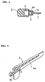
- a protective cover 4 having a semi-U-shaped cross section and capable of housing the edge 1a of the blade 1 within its own groove 4a from the open side is provided as shown in FIGS. 4 and 5.
- the protective cover 4 revolves around the pivot 5 located at the bottom end of the handle within the housing groove 3.
- the top end of the protective cover 4 is biased by a spring 6 which is positioned between the pivot 5 and the bottom end of the handle so that the protective cover 4 is constantly pushed into the housing groove 3.
- a contact surface 16 is formed at the base end of the protective cover 4, i.e., the part closer to the bottom of the handle.
- the top end of the blade 1 comes into contact with this part.
- the folding saw described in FIGS. 1 to 5 above operates as follows.
- the claw 15 of the stopper 12 provided at the top end of the handle 2 engages with the cut 10 formed at the base end of the blade 1.
- the resiliency of the spring 14 works to maintain the engagement, and the protective cover 4 arranged inside the housing groove 3 is pushed by the resiliency of the spring 6 towards the inside of the housing groove 3 so that it does not project out of the profile of the handle 2.
- the claw 15 is raised against the resiliency of the spring 14, disengaging the stopper from the cut 10.
- the blade 1 can then be revolved in the folding direction as shown in FIG. 2.
- the top end of the blade 1 enters into the housing groove 3 of the handle 2, and the top end of the edge 1a comes into contact with the contact surface 16 of the protective cover 4.
- the protective cover 4 revolves outward against the resiliency of the spring 6, and the top portion projects out of the housing groove 3 as shown in FIG. 1.
- the portion of the protective cover 4 projecting out of the housing groove 3 covers the middle portion of the edge 1a that is not completely housed inside the housing groove 3 of the handle 2. In this way, it is possible to prevent the edge of the blade from coming into contact with and injuring a finger or damaging an object while the saw is being carried or otherwise handled.
- the cut 11 formed on the base end of the blade is engaged by the claw 15 of the stopper 12, thereby locking the blade 1.
- the protective cover 4 covers the blade edge 1a is firmly maintained.
- the resiliency of the spring 6 works in the direction to return the protective cover 4 to the inside of the housing groove 3 of the handle 2.
- the protective cover 4 acts on the blade via the contact surface 16 to open the blade, but because a locking device, i.e., the stopper, is provided, the ready-to-cut condition in which the blade is folded is stably maintained despite the resiliency of the spring 6.
- FIG. 6 shows an embodiment of a folding saw combining a concavely curved blade 1 and a straight handle 2.
- this embodiment also includes a protective cover 4 inside the housing groove 3 of the handle 2 having a semi-U-shaped cross section.
- FIG. 6 (a) shows a ready-to-cut condition in which the blade 1 is unfolded
- FIG. 6 (b) shows a ready-to-carry condition in which the blade 1 is folded.
- the movement of the protective cover is similar to that in the above embodiment.
- the protective cover which is designed to revolve inside the housing groove, covers a portion of the blade 1, more specifically, the portion of the concavely curved edge 1a that is exposed from the housing groove 3 of the straight handle 2.
- FIG. 7 shows yet another embodiment of a folding saw combining a blade 1 having a straight edge 1a and a concavely curved handle 2.
- This embodiment also includes a protective cover 4 inside the housing groove 3 of the handle 2 having a semi-U-shaped cross section as in the previously described embodiments.
- FIG. 7 (a) shows the ready-to-cut condition in which the blade 1 is unfolded
- FIG. 7 (b) shows the ready-to-carry condition in which the blade 1 is folded.
- the movement of the protective cover is similar to that previously explained with respect to FIGS. 1 to 3.
- the protective cover which is provided inside the concavely curved housing groove, covers a portion of the blade 1, more specifically, the portion of the straight edge 1a that is exposed from the housing groove 3 of the concavely curved handle 2.
- FIGS. 8 to 13 also includes a protective cover inside the housing groove 3 of the handle 2, as in the embodiments shown in FIGS. 1 to 7, and this protective cover revolves around the pivot 5 which is positioned close to the bottom end of the handle.
- a spring 7 is provided at a position between the pivot 5 and the middle of the handle 2, and this spring 7 acts on the protective cover 4 housed inside the housing groove 3 so that the protective cover 4 is constantly pushed outwards from the housing groove 3. Because of this, when the blade 1 unfolded, the protective cover 4 projects out of the housing groove of the handle 2 as indicated by the two-dot chain lines in FIG. 8.
- the edge 1a first comes into contact with the protective cover 4, then enters the protective cover groove 4a, and in that condition, pushes the protective cover 4 into the housing groove 3.
- the protective cover is constantly energized to cover the edge 1a of the blade, making it safe to carry.
- the embodiment shown in FIG. 8 employs a special shape for the protective cover 4.
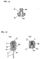
- the protective cover 4, which revolves around the pivot 5, comprises a narrow part 4b which enters the housing groove 3 and does not affect the holding of the handle 2 and a wide part 4c which projects out of the housing groove 3.
- the cross section of the outside of the wide part 4c (the lower half in FIG. 11) has a cross section that forms a continuous profile with the cross section of the handle 2.
- the protective cover 4 is activated by a spring. But the protective cover need not be acted on by a spring as long as it is capable of covering the edge part of the blade.
- the embodiment shown in FIG. 14 includes a protective cover which is revolvable around the pivot 5 and equipped with an opener 8.
- the opener 8 projects from the bottom-of-the-handle side of the pivot 5.
- the handle 2 is provided with an engagement protrusion 17 facing the housing groove 3
- the protective cover 18 is provided with an engagement protrusion 18 for engaging with the engagement protrusion 17 so that the protrusions form a click mechanism that maintains the protective cover in the housing groove or in the projected condition.
- the edge part that is exposed from the housing groove of the handle when the blade is folded is covered by a protective cover.
- a folding saw equipped with such a protective cover is safe because the edge of the blade cannot injure the holder while being carried.
- this folding saw has the effect of preventing the edge from accidentally coming into contact with and damaging other objects or, conversely, being damaged by such contact.
- the protective cover attached to the handle is constantly housed inside the housing groove of the handle, without posing an obstacle when holding the handle.
- the protective cover is projected against the resiliency of the spring, thereby firmly protecting the edge part of the blade.
- the folded condition in which a part of the blade presses a part of the protective cover against the resiliency of the spring is firmly maintained, completely eliminating the possibility that the blade will open slightly due to the resiliency of the spring and exposing the blade edge.
- the blade is folded until eventually the protective cover is pressed against the edge of the blade due to the resiliency of the spring, when the edge of the blade is completely covered by the protective cover, so that a condition in which the edge of the blade is inadvertently exposed can be prevented.
- the holder of the saw can choose to have the edge of the blade covered or to leave it uncovered. Moreover, because no spring is used inside the handle, the construction is simple, and it is possible to provide a folding saw equipped with a protective cover cheaply.
Landscapes
- Engineering & Computer Science (AREA)
- Mechanical Engineering (AREA)
- Sawing (AREA)
- Knives (AREA)
- Toys (AREA)
- Mechanical Pencils And Projecting And Retracting Systems Therefor, And Multi-System Writing Instruments (AREA)
Applications Claiming Priority (4)
| Application Number | Priority Date | Filing Date | Title |
|---|---|---|---|
| JP27027399 | 1999-09-24 | ||
| JP27027399 | 1999-09-24 | ||
| JP2000110794A JP3481548B2 (ja) | 1999-09-24 | 2000-04-12 | 折り畳み鋸 |
| JP2000110794 | 2000-04-12 |
Publications (3)
| Publication Number | Publication Date |
|---|---|
| EP1086770A2 true EP1086770A2 (de) | 2001-03-28 |
| EP1086770A3 EP1086770A3 (de) | 2002-08-21 |
| EP1086770B1 EP1086770B1 (de) | 2004-11-17 |
Family
ID=26549139
Family Applications (1)
| Application Number | Title | Priority Date | Filing Date |
|---|---|---|---|
| EP00116323A Expired - Lifetime EP1086770B1 (de) | 1999-09-24 | 2000-07-27 | Säge mit einklappbarem Sägeblatt |
Country Status (7)
| Country | Link |
|---|---|
| US (1) | US6463663B1 (de) |
| EP (1) | EP1086770B1 (de) |
| JP (1) | JP3481548B2 (de) |
| KR (1) | KR20010039612A (de) |
| AT (1) | ATE282498T1 (de) |
| DE (1) | DE60015886D1 (de) |
| TW (1) | TW473421B (de) |
Cited By (1)
| Publication number | Priority date | Publication date | Assignee | Title |
|---|---|---|---|---|
| EP1243369A1 (de) * | 2001-03-22 | 2002-09-25 | Kanzawa Seiko Co., Ltd | Säge mit einklappbarem Sägeblatt |
Families Citing this family (17)
| Publication number | Priority date | Publication date | Assignee | Title |
|---|---|---|---|---|
| CA111087S (en) * | 2005-01-06 | 2006-09-06 | Kanzawa Seiko Co Ltd | Saw blade |
| US8241263B2 (en) | 2005-08-26 | 2012-08-14 | Medline Industries, Inc. | Absorbent article |
| US7168172B1 (en) * | 2006-05-02 | 2007-01-30 | Kuang Pin Wang | Saw |
| US20080301949A1 (en) * | 2007-06-11 | 2008-12-11 | Agnete Enga | Pruning saw |
| USD584934S1 (en) * | 2008-01-03 | 2009-01-20 | Pedro Feliciano | Foldable saw |
| JP5435401B2 (ja) * | 2009-12-24 | 2014-03-05 | 日立工機株式会社 | 鋸刃及び往復動のこぎり |
| US10117792B2 (en) | 2010-10-19 | 2018-11-06 | Medline Industries, Inc. | Absorbent articles and methods of manufacturing the same |
| US8939054B2 (en) * | 2011-08-29 | 2015-01-27 | Buck Knives, Inc. | Lock for a flip open knife, and mechanism for making same automatic |
| USD716938S1 (en) | 2011-10-19 | 2014-11-04 | Medline Industries, Inc. | Absorbent core |
| US9486368B2 (en) | 2013-12-05 | 2016-11-08 | Medline Industries, Inc. | Disposable hygienic article with means for diagnostic testing |
| US10226388B2 (en) | 2014-04-21 | 2019-03-12 | Medline Industries, Inc. | Stretch breathable protective absorbent article using tri-laminate |
| US9622922B2 (en) | 2014-04-21 | 2017-04-18 | Medline Industries, Inc. | Stretch breathable protective absorbent article using bilaminate |
| USD955845S1 (en) * | 2020-10-15 | 2022-06-28 | Fiskars Finland Oy Ab | Saw |
| USD951054S1 (en) * | 2020-10-15 | 2022-05-10 | Fiskars Finland Oy Ab | Saw |
| USD951053S1 (en) * | 2020-10-15 | 2022-05-10 | Fiskars Finland Oy A | Saw |
| USD959229S1 (en) * | 2020-10-15 | 2022-08-02 | Fiskars Finland Oy Ab | Saw |
| USD966859S1 (en) * | 2020-10-16 | 2022-10-18 | Fiskars Finland Oy Ab | Folding saw |
Family Cites Families (13)
| Publication number | Priority date | Publication date | Assignee | Title |
|---|---|---|---|---|
| US338853A (en) * | 1886-03-30 | Combined knife and fork | ||
| US744934A (en) * | 1903-03-25 | 1903-11-24 | William R Owens | Combination implement for desk use. |
| US770118A (en) * | 1903-12-17 | 1904-09-13 | Milton H Rowland | Folding hunting-knife. |
| US924070A (en) * | 1908-08-28 | 1909-06-08 | Daniel H Holman | Hunting-knife. |
| US1638749A (en) * | 1925-12-21 | 1927-08-09 | Guillermo F Santoyo | Pruning saw |
| US4203214A (en) * | 1978-08-07 | 1980-05-20 | Saran Industries, Inc. | Knife |
| US5781998A (en) * | 1993-12-23 | 1998-07-21 | Stamper; James D. | Sheath style folding knife |
| USD383370S (en) * | 1996-03-05 | 1997-09-09 | Fiskars Inc. | Knife handle with blade guard |
| JPH10291202A (ja) * | 1997-04-17 | 1998-11-04 | Saboten:Kk | 折り畳み鋸 |
| US5924210A (en) * | 1998-01-16 | 1999-07-20 | Hung; Shen Chi | Saw having angle adjusting device |
| US5926962A (en) * | 1998-09-18 | 1999-07-27 | Chen; Wen-Ger | Handle of a saw |
| SE512976C2 (sv) * | 1998-10-27 | 2000-06-12 | Kapman Ab | Handsåg |
| SE516255C2 (sv) * | 2000-04-26 | 2001-12-10 | Kapman Ab | Handsåg med utdragbart skydd |
-
2000
- 2000-04-12 JP JP2000110794A patent/JP3481548B2/ja not_active Expired - Fee Related
- 2000-05-17 KR KR1020000026546A patent/KR20010039612A/ko not_active Withdrawn
- 2000-06-08 TW TW089111185A patent/TW473421B/zh not_active IP Right Cessation
- 2000-07-27 DE DE60015886T patent/DE60015886D1/de not_active Expired - Lifetime
- 2000-07-27 AT AT00116323T patent/ATE282498T1/de not_active IP Right Cessation
- 2000-07-27 EP EP00116323A patent/EP1086770B1/de not_active Expired - Lifetime
- 2000-09-20 US US09/665,480 patent/US6463663B1/en not_active Expired - Fee Related
Cited By (1)
| Publication number | Priority date | Publication date | Assignee | Title |
|---|---|---|---|---|
| EP1243369A1 (de) * | 2001-03-22 | 2002-09-25 | Kanzawa Seiko Co., Ltd | Säge mit einklappbarem Sägeblatt |
Also Published As
| Publication number | Publication date |
|---|---|
| ATE282498T1 (de) | 2004-12-15 |
| JP3481548B2 (ja) | 2003-12-22 |
| JP2001158001A (ja) | 2001-06-12 |
| EP1086770A3 (de) | 2002-08-21 |
| DE60015886D1 (de) | 2004-12-23 |
| KR20010039612A (ko) | 2001-05-15 |
| EP1086770B1 (de) | 2004-11-17 |
| US6463663B1 (en) | 2002-10-15 |
| TW473421B (en) | 2002-01-21 |
Similar Documents
| Publication | Publication Date | Title |
|---|---|---|
| US6463663B1 (en) | Folding saw | |
| US6161290A (en) | Utility knife | |
| US7480997B2 (en) | Foldable knife | |
| US5852874A (en) | Carton cutting device having a pivotal guard member | |
| EP1243369A1 (de) | Säge mit einklappbarem Sägeblatt | |
| EP1034900B1 (de) | Sicherheitsmesser | |
| EP0634252B1 (de) | Taschenmesser mit einer verriegelbaren Klinge und einer Druckknopfentriegelungsvorrichtung | |
| CA1080953A (en) | Utility knife | |
| US6195896B1 (en) | Safety knife | |
| CA2167120A1 (en) | Guarded Surgical Scalper with Scalpel Blade Remover | |
| US4563818A (en) | Can openers | |
| US4754550A (en) | Can openers | |
| JP2004337612A (ja) | 万能ナイフ | |
| US5297340A (en) | Parting tool | |
| HK1036242A (en) | Foldable saw | |
| KR200177030Y1 (ko) | 금속 절단기의 방호장치 | |
| FR2951397A1 (fr) | Couteau d'ebavurage | |
| JPS6033776Y2 (ja) | 折畳み替刃鎌 | |
| JPH1014651A (ja) | 拡大レンズ付き爪切り器 | |
| JPH0527147Y2 (de) | ||
| KR200207914Y1 (ko) | 과수용 가위 | |
| JP2002096303A (ja) | 折り畳み鋸 | |
| JPS5824809Y2 (ja) | フイルム包装機 | |
| JPH10291202A (ja) | 折り畳み鋸 | |
| GB2174947A (en) | Folding knife |
Legal Events
| Date | Code | Title | Description |
|---|---|---|---|
| PUAI | Public reference made under article 153(3) epc to a published international application that has entered the european phase |
Free format text: ORIGINAL CODE: 0009012 |
|
| AK | Designated contracting states |
Kind code of ref document: A2 Designated state(s): AT BE CH CY DE DK ES FI FR GB GR IE IT LI LU MC NL PT SE |
|
| AX | Request for extension of the european patent |
Free format text: AL;LT;LV;MK;RO;SI |
|
| PUAL | Search report despatched |
Free format text: ORIGINAL CODE: 0009013 |
|
| AK | Designated contracting states |
Kind code of ref document: A3 Designated state(s): AT BE CH CY DE DK ES FI FR GB GR IE IT LI LU MC NL PT SE |
|
| AX | Request for extension of the european patent |
Free format text: AL;LT;LV;MK;RO;SI |
|
| 17P | Request for examination filed |
Effective date: 20021108 |
|
| AKX | Designation fees paid |
Designated state(s): AT BE CH CY DE DK ES FI FR GB GR IE IT LI LU MC NL PT SE |
|
| GRAP | Despatch of communication of intention to grant a patent |
Free format text: ORIGINAL CODE: EPIDOSNIGR1 |
|
| 17Q | First examination report despatched |
Effective date: 20040430 |
|
| GRAS | Grant fee paid |
Free format text: ORIGINAL CODE: EPIDOSNIGR3 |
|
| GRAA | (expected) grant |
Free format text: ORIGINAL CODE: 0009210 |
|
| PUAC | Information related to the publication of a b1 document modified or deleted |
Free format text: ORIGINAL CODE: 0009299EPPU |
|
| STAA | Information on the status of an ep patent application or granted ep patent |
Free format text: STATUS: THE APPLICATION HAS BEEN WITHDRAWN |
|
| AK | Designated contracting states |
Kind code of ref document: B1 Designated state(s): AT BE CH CY DE DK ES FI FR GB GR IE IT LI LU MC NL PT SE |
|
| REG | Reference to a national code |
Ref country code: GB Ref legal event code: FG4D |
|
| DB1 | Publication of patent cancelled | ||
| 18W | Application withdrawn |
Effective date: 20040929 |
|
| REG | Reference to a national code |
Ref country code: IE Ref legal event code: FG4D |
|
| REG | Reference to a national code |
Ref country code: GB Ref legal event code: ERR Free format text: THE ABOVE EP(UK) PATENT WAS ADVERTISED IN THE PATENTS AND DESIGNS JOURNAL NO. 6026 DATED 20041117 AS GRANTED BY THE EUROPEAN PATENT OFFICE (EPO) WITH EFFECT FROM THAT DATE. THE GRANT DATE WAS HOWEVER DELETED BY THE EPO IN EUROPEAN PATENT BULLETIN NO. 2004/48 DATED 20041124. THE PATENT WAS ACTUALLY WITHDRAWN AT THE EPO ON 20040929. |
|
| REF | Corresponds to: |
Ref document number: 60015886 Country of ref document: DE Date of ref document: 20041223 Kind code of ref document: P |
|
| EN | Fr: translation not filed | ||
| REG | Reference to a national code |
Ref country code: HK Ref legal event code: WD Ref document number: 1036242 Country of ref document: HK |