EP1086783A1 - Ratschen-Werkzeug mit verbessertem Einrücken zwischen Zahnrad und Klinke - Google Patents
Ratschen-Werkzeug mit verbessertem Einrücken zwischen Zahnrad und Klinke Download PDFInfo
- Publication number
- EP1086783A1 EP1086783A1 EP99118054A EP99118054A EP1086783A1 EP 1086783 A1 EP1086783 A1 EP 1086783A1 EP 99118054 A EP99118054 A EP 99118054A EP 99118054 A EP99118054 A EP 99118054A EP 1086783 A1 EP1086783 A1 EP 1086783A1
- Authority
- EP
- European Patent Office
- Prior art keywords
- pawl
- compartment
- gear wheel
- teeth
- ratcheting tool
- Prior art date
- Legal status (The legal status is an assumption and is not a legal conclusion. Google has not performed a legal analysis and makes no representation as to the accuracy of the status listed.)
- Withdrawn
Links
Images



Classifications
-
- B—PERFORMING OPERATIONS; TRANSPORTING
- B25—HAND TOOLS; PORTABLE POWER-DRIVEN TOOLS; MANIPULATORS
- B25B—TOOLS OR BENCH DEVICES NOT OTHERWISE PROVIDED FOR, FOR FASTENING, CONNECTING, DISENGAGING, OR HOLDING
- B25B13/00—Spanners; Wrenches
- B25B13/46—Spanners; Wrenches of the ratchet type, for providing a free return stroke of the handle
- B25B13/461—Spanners; Wrenches of the ratchet type, for providing a free return stroke of the handle with concentric driving and driven member
- B25B13/462—Spanners; Wrenches of the ratchet type, for providing a free return stroke of the handle with concentric driving and driven member the ratchet parts engaging in a direction radial to the tool operating axis
- B25B13/463—Spanners; Wrenches of the ratchet type, for providing a free return stroke of the handle with concentric driving and driven member the ratchet parts engaging in a direction radial to the tool operating axis a pawl engaging an externally toothed wheel
Definitions
- the present invention relates to an improved gear wheel/pawl engagement for a ratcheting tool, e.g., a ring spanner or a combination wrench having a box end.
- a ratcheting tool e.g., a ring spanner or a combination wrench having a box end.
- U.S. Patent No. 3,838,614 to O'Donnell issued on Oct. 1, 1974 discloses a ratcheting tool including a ratchet gear 26 mounted in a box end of a tool handle 1.
- a compression spring 20 is mounted in an elongated compartment 12 in the web area for biasing a double tooth dog 22 to engage with the ratchet gear 26.
- the elongated compartment 12 is slant to provide improved engaging effect between the double tooth dog and the ratchet gear. Yet, manufacture of this slant, elongated compartment 12 is relatively difficult, and an additional ratchet cover 14 that adversely affects the aesthetically pleasing effect is required.
- U.S. Patent No. 4,991,468 to Lee issued on Feb. 12, 1991 discloses a wrench body including a driver wheel 17 mounted in a head 10 thereof.
- a spring 18 is mounted in lateral hole 102 in the head 10 for biasing a pawl 40 to engage with the ratchet gear 26.
- a tiny plate 19 is provided to seal the hole 102 and to which an end of the spring 18 is attached. Nevertheless, it is difficult to control position of the tiny plate 19 that affects the biasing force of the spring 18. In some cases, the driver wheel 17 is stuck.
- U.S. Patent No. 5,636,557 to Ma issued on Jun. 10, 1997 discloses a ratchet type ring spanner including a ratchet wheel 20 mounted in a box end of a ring spanner.
- a spring 16 is mounted in a slant manner for urging an arcuate toothed member 14 to engage with the ratchet wheel 20.
- a stop member 15 is utilized to provide a support for positioning the spring 16.
- the stop member 15 results in a difficult assembly procedure.
- the arcuate toothed member 14 has a long travel and thus tends to be stuck and requires a larger head for receiving the arcuate toothed member 14.
- Fig. 12 of the drawings illustrates a ratcheting tool including a ratchet wheel 1' mounted in a box end thereof.
- a spring 3' is mounted in a cavity 4' in the web area of the tool for urging a pawl 2' to engage with the ratchet wheel 1'.
- installation of and positioning for the spring 3' are big problems such that the spring 3' tends to disengage from the pawl 2'.
- the pawl 2' has a long travel and thus tends to be stuck during its return travel.
- Fig. 13 of the drawings illustrates a ratcheting tool 11' with a ratchet wheel 7' mounted in a head thereof for engaging with a socket 8'.
- a hole 9' is defined in the ratchet wheel 7' for receiving a positioning member 5' with a dome head.
- a spring 6' is mounted in the hole 9' for biasing the dome head of the positioning member 5' outward to engage with one of a number of arcuate recesses 10' in an outer periphery of the socket 8'.
- the ratchet wrench includes too many components and thus is troublesome to assemble.
- the driving torque of this ratchet wrench is relatively low, as the positioning effect between the dome head of the positioning member 5' and the arcuate recess 10' is poor.
- Figs. 14 and 15 of the drawings illustrate a ratcheting tool 12' including a number of teeth 13' in an inner periphery of a box end thereof.
- a ratchet wheel 14' is mounted in the box end of the ratcheting tool 12' and includes a number of annularly spaced groove 15' in an outer periphery thereof.
- a positioning member 16' is secured in each groove 15' and located between the teeth 13' in the box end and the ratchet wheel 14', thereby providing an engaging effect. Nevertheless, the positioning member 16' is too small and thus provides poor driving torque.
- assembly for this ratchet wheel is troublesome, as it has too many components.
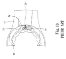
- Fig. 16 of the drawings illustrates a ratcheting tool 17' including a ratchet wheel 18' mounted in a box end thereof.
- a pawl 19' is mounted in a cavity 21' in a web area of the tool 17' and biased by a spring 20' to engage with the ratchet wheel 18'.
- the pawl 19' includes a notch 22' for receiving an end of the spring 20'. Nevertheless, it is not easy to secure the spring 20' in the cavity 21'. As a result, the spring 20' tends to disengage from the pawl 19' and thus adversely affects the ratcheting function.
- the driving torque provided by the ratcheting tool is accordingly low.
- the spring merely provides a radial force for biasing the pawl 19' to engage with the ratchet wheel 18', yet no horizontal force is imparted to the pawl 19' and thus fails to provide the function of ratcheting in a single direction.
- Figs. 17 and 18 of the drawings illustrate a reversible ring spanner including a ratchet wheel 24' mounted in a box end 23' thereof.
- a spring 27' is mounted in a cavity 26' in a web area of the ring spanner for biasing a pawl 25' to engage with the ratchet wheel 24'. It is found that the pawl 25' with a single tooth is not capable of providing the required retaining effect. The ratchet wheel tends to be stuck. The driving torque of the spanner is poor.
- the above-mentioned conventional ratcheting tools fail to provide high torque operation, as the pawl merely engages with the ratchet wheel by at best three teeth. If the teeth number of the pawl is increased, the head of the ratcheting tool has to be enlarged to accommodate the pawl and thus is difficult to be used in a limited space. In addition, free rotation of the ratcheting tool during ratcheting is too large (larger than the theoretic value of 5°), as the pawl has a long travel.
- the present invention is intended to provide an improved gear wheel/pawl engagement for a ratcheting tool that mitigates and/or obviates the above problems.
- the pawl engages with the gear wheel by at least twelve teeth and thus may bear a higher torque during ratcheting.
- a ratcheting tool comprises:
- the wall defining the second compartment includes a cavity for receiving the biasing means.
- the biasing means includes a ball partially received in the cavity and an elastic member mounted in the cavity for biasing the ball to exert a force on the operative section.
- the operative section is preferably rectilinear.
- the second side of the pawl includes an eccentrically located groove with a rectilinear section.
- a ratcheting tool comprising:
- the ratcheting tool in accordance with the present invention may bear much higher torque and has the minimum free rotating angle that is very useful when operating in a limited space.
- a ratcheting tool in accordance with the present invention is in the form of a combination wrench 100 having a handle 101, a box end 10, and an open end 102.
- the box end 10 includes a first compartment 11.
- a web area (not labeled) between the handle 101 and the box end 10 includes a second compartment 12 that communicates with the first compartment 11.
- a wall that defines the second compartment 12 includes a cavity 13.
- the box end 10 further includes an annular ledge 14 in a lower end thereof.
- a gear wheel 20 is rotatably mounted in the first compartment 11 and rests on the annular ledge 14.
- the gear wheel 20 includes an inner periphery 21 for engaging with a fastener to be tightened or loosened and a plurality of teeth 22 in an outer periphery thereof.
- An annular groove 23 is defined in a lower end of the outer periphery of the gear wheel 20 for receiving a C-clip 24, thereby retaining the gear wheel 20 in the first compartment 11.
- a pawl 30 is mounted in the second compartment 12 and includes an arcuate first side facing the gear wheel teeth 22.
- the arcuate first side has a plurality of teeth 31.
- the pawl 30 further includes a second side facing away the gear wheel teeth 22.
- the second side includes an eccentrically located groove 32 with a rectilinear section 321 that is proximal to a longitudinal axis thereof and that is at an angle with a longitudinal direction of the handle 101.
- a biasing means 40 is mounted in the cavity 13.
- the biasing means 40 includes a ball 41 engaged with a wall defining the groove 32 and an elastic member 42 for biasing the ball 41 to engage with the wall defining the groove 32.
- the ratcheting tool after assembly is shown in Fig. 3. It is appreciated that the pawl 30 engages with the gear wheel 20 by at least twelve (12) teeth and thus may bear higher torque during ratcheting. It is noted that the ball 41 exerts a force on the rectilinear section 321 of the second side of the pawl 30 under the action of the elastic member 42. As a result, the force is imparted into a radial (horizontal) force to urge the pawl 30 along the radial direction to securely engage with the teeth 22 of the gear wheel 20 and a downward force (as seen from Fig. 3) to urge the pawl 30 to bear against the wall defining the second compartment 12. Thus, the torque acting on the pawl 30 during ratcheting is transmitted to the wall defining the second compartment 12.
- Figs. 4 through 8 illustrate free rotation of the gear wheel 20. It is noted that the pawl 30 re-engages with the gear wheel teeth 22 after the gear wheel 20 is rotated through 5° (for a gear wheel with seventy-two (72) teeth). More specifically, the ratcheting tool has a minimum free rotating angle during ratcheting, which is impossible to be achieved by conventional ratcheting tools.
- Figs. 9-11 illustrate modified embodiments of the ratcheting tool in accordance with the present invention, wherein the pawl 30 is modified to have different contours without affecting its function.
- the ratcheting tool in accordance with the present invention may bear much higher torque and has the minimum free rotating angle that is very useful when operating in a limited space.
Landscapes
- Engineering & Computer Science (AREA)
- Mechanical Engineering (AREA)
- Details Of Spanners, Wrenches, And Screw Drivers And Accessories (AREA)
Priority Applications (2)
| Application Number | Priority Date | Filing Date | Title |
|---|---|---|---|
| US09/368,963 US6134990A (en) | 1999-08-05 | 1999-08-05 | Ratcheting tool with improved gear wheel/pawl engagement |
| EP99118054A EP1086783A1 (de) | 1999-08-05 | 1999-09-22 | Ratschen-Werkzeug mit verbessertem Einrücken zwischen Zahnrad und Klinke |
Applications Claiming Priority (2)
| Application Number | Priority Date | Filing Date | Title |
|---|---|---|---|
| US09/368,963 US6134990A (en) | 1999-08-05 | 1999-08-05 | Ratcheting tool with improved gear wheel/pawl engagement |
| EP99118054A EP1086783A1 (de) | 1999-08-05 | 1999-09-22 | Ratschen-Werkzeug mit verbessertem Einrücken zwischen Zahnrad und Klinke |
Publications (1)
| Publication Number | Publication Date |
|---|---|
| EP1086783A1 true EP1086783A1 (de) | 2001-03-28 |
Family
ID=26153112
Family Applications (1)
| Application Number | Title | Priority Date | Filing Date |
|---|---|---|---|
| EP99118054A Withdrawn EP1086783A1 (de) | 1999-08-05 | 1999-09-22 | Ratschen-Werkzeug mit verbessertem Einrücken zwischen Zahnrad und Klinke |
Country Status (2)
| Country | Link |
|---|---|
| US (1) | US6134990A (de) |
| EP (1) | EP1086783A1 (de) |
Families Citing this family (56)
| Publication number | Priority date | Publication date | Assignee | Title |
|---|---|---|---|---|
| US6148695A (en) | 1999-08-03 | 2000-11-21 | Hu; Bobby | Ratchet wheel with asymmetric arcuate concave teeth or non-arcuate concave teeth and ratcheting tools with such ratchet wheel |
| US6568299B2 (en) | 1999-12-16 | 2003-05-27 | Bobby Hu | Reversible ratcheting tool with a smaller head |
| US6431031B1 (en) | 1999-12-16 | 2002-08-13 | Bobby Hu | Reversible ratcheting tool with a smaller head |
| TW418748U (en) | 2000-01-11 | 2001-01-11 | Hu Hou Fei | Ratchet wrench |
| TW408653U (en) | 2000-02-03 | 2000-10-11 | Hu Hou Fei | Ratcheting tool |
| JP3515763B2 (ja) | 2000-03-13 | 2004-04-05 | 厚飛 胡 | 小ヘッドと改善駆動トルクを具えたリバーシブルラチェット工具 |
| TW428513U (en) | 2000-07-21 | 2001-04-01 | Hu Hou Fei | Locating device of a direction switch and ratchet tools using the same |
| TW437521U (en) | 2000-08-22 | 2001-05-28 | Hu Hou Fei | Ratchet driven tool |
| TW444633U (en) | 2000-09-01 | 2001-07-01 | Hu Hou Fei | Ratchet tool |
| US6745647B2 (en) | 2000-11-29 | 2004-06-08 | Mei-Chen Wang | Wrench having a universal-joint ratchet wheel |
| USD459960S1 (en) | 2001-01-10 | 2002-07-09 | Hung Yin Wei | Plum blossom shaped ratchet wrench |
| TW489701U (en) | 2001-02-19 | 2002-06-01 | Hou-Fei Hu | A ratchet driven wrench capable of easily manufacturing and fabricating |
| US6807882B2 (en) | 2001-05-07 | 2004-10-26 | Bobby Hu | Wrench with a simplified structure |
| US6722234B2 (en) | 2001-05-14 | 2004-04-20 | Bobby Hu | Easy-to-operate and easy-to-assemble ratcheting-type wrench |
| TW483365U (en) | 2001-07-13 | 2002-04-11 | Hou-Fei Hu | High torque wrench |
| TW483377U (en) | 2001-07-13 | 2002-04-11 | Hou-Fei Hu | Micro small torque wrench with constant torque value |
| USD477756S1 (en) | 2001-07-23 | 2003-07-29 | Hand Tools Design Corporation | Tool and reversing lever |
| USD474381S1 (en) | 2001-07-23 | 2003-05-13 | Hand Tools Design Corporation | Tool and reversing lever |
| US6647832B2 (en) | 2001-07-27 | 2003-11-18 | Bobby Hu | Wrench having two rigid supporting areas for a pawl |
| US6539825B1 (en) | 2001-09-20 | 2003-04-01 | Yen-Wen Lin | Single direction ratcheting wrench with stuck prevention and ratcheting direction indication |
| TW503802U (en) | 2001-10-17 | 2002-09-21 | Hou-Fei Hu | Invertible ratchet wrench |
| US6450066B1 (en) | 2001-10-19 | 2002-09-17 | Bobby Hu | Head of a wrench handle |
| US6520051B1 (en) | 2001-12-27 | 2003-02-18 | Bobby Hu | Head of a wrench handle |
| TW506308U (en) | 2002-02-08 | 2002-10-11 | Hou-Fei Hu | Improved structure for ratchet wrench |
| US6945141B2 (en) | 2002-04-22 | 2005-09-20 | Bobby Hu | Reversible ratchet type wrench |
| TW567123B (en) | 2002-07-22 | 2003-12-21 | Hou-Fei Hu | Ratchet wrench capable of fast rotation |
| TWI245684B (en) | 2002-08-05 | 2005-12-21 | Yan-Wen Lin | Simple ratchet wrench |
| EP1391267A3 (de) * | 2002-08-20 | 2006-08-16 | Hand Tool Design Corporation | Reversibles Ratschenwerkzeug |
| USD488037S1 (en) | 2003-04-16 | 2004-04-06 | Lea Way Hand Tool Corporation | Ratchet wrench |
| USD486366S1 (en) | 2003-04-28 | 2004-02-10 | Lea Way Hand Tool Corporation | Ratchet wrench |
| USD486708S1 (en) | 2003-04-28 | 2004-02-17 | Lea Way Hand Tool Corporation | Ratchet wrench |
| US20050044997A1 (en) * | 2003-08-25 | 2005-03-03 | Liu Ling Lang | High torsional force structure for a ratchet device |
| TW592900B (en) * | 2003-08-29 | 2004-06-21 | Shiou-Ching Huang | One-way driving wrench having protective device |
| CN100384594C (zh) * | 2003-10-09 | 2008-04-30 | 陈泰佐 | 具保护装置的单向驱动扳手 |
| US7263919B2 (en) * | 2004-09-10 | 2007-09-04 | Easco Handtools, Inc. | Ratcheting tool with vertically curved tooth arrangement |
| US7073412B1 (en) * | 2004-10-12 | 2006-07-11 | Easco Hand Tools, Inc. | Method of forming a pawl pocket for a ratcheting tool and tool thereby formed |
| US7152508B2 (en) * | 2004-12-08 | 2006-12-26 | Irwin Industrial Tool Company | Ratchet extraction wrench |
| USD552440S1 (en) * | 2006-07-25 | 2007-10-09 | Proxene Tools Co., Ltd. | Spanner |
| US8069753B2 (en) * | 2009-11-12 | 2011-12-06 | Meridian International Co., Ltd. | Rotary ratchet wrench |
| CN201693485U (zh) | 2010-05-28 | 2011-01-05 | 上海美瑞实业有限公司 | 一种套筒棘轮扳手 |
| US8459151B2 (en) | 2010-05-28 | 2013-06-11 | Meridian International Co., Ltd. | Ratcheting socket wrench and sockets |
| US8820195B2 (en) | 2010-07-01 | 2014-09-02 | Stanley Black & Decker, Inc. | Bit or fastener driver |
| CN201808053U (zh) | 2010-08-17 | 2011-04-27 | 上海美瑞实业有限公司 | 多功能套筒架 |
| TW201221309A (en) * | 2010-11-25 | 2012-06-01 | zhen-kun Chen | Unidirectional ratchet device |
| TW201226121A (en) * | 2010-12-24 | 2012-07-01 | Honiton Ind Inc | Ratchet wrench structure |
| CN102788103B (zh) * | 2011-05-19 | 2015-01-07 | 陈振坤 | 单向棘轮元件 |
| US9114509B2 (en) | 2012-02-14 | 2015-08-25 | Meridian International Co., Ltd. | Rotary ratcheting wrench |
| CN104827427B (zh) * | 2014-02-10 | 2016-08-17 | 志拓有限公司 | 易装配的棘轮扳手 |
| TWI608907B (zh) * | 2017-04-12 | 2017-12-21 | Reversible ratchet wrench | |
| US11298807B2 (en) | 2017-10-31 | 2022-04-12 | Hubbell Incorporated | Ratcheting box torque wrench |
| USD1012643S1 (en) | 2021-12-21 | 2024-01-30 | Matco Tools Corporation | Ratchet pawl |
| US12138748B2 (en) | 2021-12-21 | 2024-11-12 | Matco Tools Corporation | Ratchet mechanism and ratchet pawl |
| USD1116673S1 (en) * | 2023-01-14 | 2026-03-10 | Harbor Freight Tools Usa, Inc. | Rachet sleeve |
| US20250229387A1 (en) * | 2024-01-16 | 2025-07-17 | Harbor Freight Tools Usa, Inc. | Ratchet Tool Including Pawl with Biasing Effect |
| USD1123549S1 (en) * | 2024-02-16 | 2026-04-28 | Stanley Black & Decker, Inc. | Gear for a hand tool |
| USD1122706S1 (en) * | 2024-02-16 | 2026-04-21 | Stanley Black & Decker Inc. | Gear for a hand tool |
Citations (12)
| Publication number | Priority date | Publication date | Assignee | Title |
|---|---|---|---|---|
| CH132668A (de) * | 1929-04-10 | 1929-04-30 | Flueckiger Gottfried | Schraubenschlüssel. |
| GB872911A (en) * | 1960-04-13 | 1961-07-12 | Terence Gordon Hare | Improvements in or relating to manually operated wrenches |
| US3393780A (en) * | 1967-01-26 | 1968-07-23 | Luther E. Kilness | Reversible ratchet |
| DE1810811A1 (de) * | 1968-11-25 | 1970-06-11 | Soc D Forges Stephanoises | Schraubenschluessel mit Ratsche |
| US3838614A (en) | 1972-12-12 | 1974-10-01 | Donnell W O | Reciprocating engine barring tool |
| US4485700A (en) * | 1983-01-26 | 1984-12-04 | Colvin David S | Reversible ratchet wrench |
| EP0734813A1 (de) * | 1995-03-27 | 1996-10-02 | Jessie Chow | Ratschenschlüssel mit Ratschenzähnen mit höherer Festigkeit |
| US5626062A (en) * | 1992-01-16 | 1997-05-06 | Colvin; David S. | Socket and ratchet wrench |
| US5636557A (en) | 1996-05-24 | 1997-06-10 | Ma; Nai-Lin | Ratchet type ring spanner |
| DE29808840U1 (de) * | 1998-05-15 | 1998-08-06 | McCann, Frank, Ta Ya Hsiang, Taichung | Ratschenschlüssel mit Steuermechanismus |
| GB2327058A (en) * | 1997-07-10 | 1999-01-13 | Frank Mccann | Ratchet wrench |
| DE29902763U1 (de) * | 1999-02-16 | 1999-06-10 | Hsieh, Chi-Ching, Fong Yuan, Taichung | Ratschensteckschlüssel |
Family Cites Families (8)
| Publication number | Priority date | Publication date | Assignee | Title |
|---|---|---|---|---|
| US4991468A (en) * | 1990-08-10 | 1991-02-12 | Lee Clark J | Barrel type sockets |
| US5499560A (en) * | 1994-05-20 | 1996-03-19 | Aeschliman; William M. | Universal open ended socket wrench |
| US5557994A (en) * | 1995-07-17 | 1996-09-24 | Nakayama; Tatsuo | Ratchet handle with torque adjustment |
| US5857390A (en) * | 1996-12-24 | 1999-01-12 | Whiteford; Carlton L. | Reversible ratchet wrench including thin-walled sockets |
| US5873286A (en) * | 1997-04-08 | 1999-02-23 | Hand Tool Design Corporation | Flex pawl |
| US5913954A (en) * | 1997-09-12 | 1999-06-22 | Hand Tool Design Corporation | Pawl for a low profile wrench |
| US5946987A (en) * | 1997-11-07 | 1999-09-07 | Wei; Hung-Yin | Offset ratchet wrench |
| US5979274A (en) * | 1998-01-07 | 1999-11-09 | Hsieh; Chih-Ching | Ratchet wheel mounting arrangement of a wrench |
-
1999
- 1999-08-05 US US09/368,963 patent/US6134990A/en not_active Expired - Lifetime
- 1999-09-22 EP EP99118054A patent/EP1086783A1/de not_active Withdrawn
Patent Citations (12)
| Publication number | Priority date | Publication date | Assignee | Title |
|---|---|---|---|---|
| CH132668A (de) * | 1929-04-10 | 1929-04-30 | Flueckiger Gottfried | Schraubenschlüssel. |
| GB872911A (en) * | 1960-04-13 | 1961-07-12 | Terence Gordon Hare | Improvements in or relating to manually operated wrenches |
| US3393780A (en) * | 1967-01-26 | 1968-07-23 | Luther E. Kilness | Reversible ratchet |
| DE1810811A1 (de) * | 1968-11-25 | 1970-06-11 | Soc D Forges Stephanoises | Schraubenschluessel mit Ratsche |
| US3838614A (en) | 1972-12-12 | 1974-10-01 | Donnell W O | Reciprocating engine barring tool |
| US4485700A (en) * | 1983-01-26 | 1984-12-04 | Colvin David S | Reversible ratchet wrench |
| US5626062A (en) * | 1992-01-16 | 1997-05-06 | Colvin; David S. | Socket and ratchet wrench |
| EP0734813A1 (de) * | 1995-03-27 | 1996-10-02 | Jessie Chow | Ratschenschlüssel mit Ratschenzähnen mit höherer Festigkeit |
| US5636557A (en) | 1996-05-24 | 1997-06-10 | Ma; Nai-Lin | Ratchet type ring spanner |
| GB2327058A (en) * | 1997-07-10 | 1999-01-13 | Frank Mccann | Ratchet wrench |
| DE29808840U1 (de) * | 1998-05-15 | 1998-08-06 | McCann, Frank, Ta Ya Hsiang, Taichung | Ratschenschlüssel mit Steuermechanismus |
| DE29902763U1 (de) * | 1999-02-16 | 1999-06-10 | Hsieh, Chi-Ching, Fong Yuan, Taichung | Ratschensteckschlüssel |
Also Published As
| Publication number | Publication date |
|---|---|
| US6134990A (en) | 2000-10-24 |
Similar Documents
| Publication | Publication Date | Title |
|---|---|---|
| US6134990A (en) | Ratcheting tool with improved gear wheel/pawl engagement | |
| US6263767B1 (en) | Pawl for a ratchet-type spanner | |
| US6539825B1 (en) | Single direction ratcheting wrench with stuck prevention and ratcheting direction indication | |
| US5636557A (en) | Ratchet type ring spanner | |
| US6644148B2 (en) | Reversible ratchet-type wrench | |
| EP1109651B1 (de) | Schraubenschlüssel mit ratschenwirkung | |
| US6971286B2 (en) | Ratcheting wrench with quick tightening/loosening functions and fine adjusting functions | |
| US7178429B2 (en) | Easy-to-assemble ratcheting tool | |
| US6807882B2 (en) | Wrench with a simplified structure | |
| US6647832B2 (en) | Wrench having two rigid supporting areas for a pawl | |
| US20030070512A1 (en) | Reversible ratchet-type wrench | |
| US4561329A (en) | Low profile ratchet wrench | |
| US20020112573A1 (en) | Easy-to-manufacture and easy-to-assemble ratcheting-type wrench | |
| US6745647B2 (en) | Wrench having a universal-joint ratchet wheel | |
| US6601477B2 (en) | Wrench adaptor allowing reversible operation | |
| GB2486830A (en) | Bias assembly for ratchet tools | |
| US7082860B2 (en) | Tang and ratchet wrench with rotating disc operated direction change of drive and ratcheting | |
| US6860175B2 (en) | Dual function retainer for a ratcheting wrench | |
| TWI853526B (zh) | 用於棘輪工具的棘爪機構及棘輪工具 | |
| US20020148332A1 (en) | Screwdriver shank with a universal joint | |
| US6976408B2 (en) | Annular wrench | |
| US6059083A (en) | Ratchet mechanism | |
| US6510765B2 (en) | Structure of a ratchet wheel having a ratchet wheel allowing a smooth teeth returning after application of the ratchet wrench | |
| US20020162423A1 (en) | Wrench with a simplified structure | |
| US6907804B2 (en) | Pawl switch member for ratchet tools |
Legal Events
| Date | Code | Title | Description |
|---|---|---|---|
| PUAI | Public reference made under article 153(3) epc to a published international application that has entered the european phase |
Free format text: ORIGINAL CODE: 0009012 |
|
| AK | Designated contracting states |
Kind code of ref document: A1 Designated state(s): AT BE CH CY DE DK ES FI FR GB GR IE IT LI LU MC NL PT SE |
|
| AX | Request for extension of the european patent |
Free format text: AL;LT;LV;MK;RO PAYMENT 19990922;SI |
|
| 17P | Request for examination filed |
Effective date: 20010228 |
|
| AKX | Designation fees paid |
Free format text: AT BE CH CY DE DK ES FI FR GB GR IE IT LI LU MC NL PT SE |
|
| AXX | Extension fees paid |
Free format text: RO PAYMENT 19990922 |
|
| 17Q | First examination report despatched |
Effective date: 20040128 |
|
| STAA | Information on the status of an ep patent application or granted ep patent |
Free format text: STATUS: THE APPLICATION IS DEEMED TO BE WITHDRAWN |
|
| 18D | Application deemed to be withdrawn |
Effective date: 20080103 |